EP1189683B1 - System and method for withdrawing permeate through a filter and for cleaning the filter in situ - Google Patents
System and method for withdrawing permeate through a filter and for cleaning the filter in situ Download PDFInfo
- Publication number
- EP1189683B1 EP1189683B1 EP00938096A EP00938096A EP1189683B1 EP 1189683 B1 EP1189683 B1 EP 1189683B1 EP 00938096 A EP00938096 A EP 00938096A EP 00938096 A EP00938096 A EP 00938096A EP 1189683 B1 EP1189683 B1 EP 1189683B1
- Authority
- EP
- European Patent Office
- Prior art keywords
- compartment
- filter
- substrate
- permeate
- vessel
- Prior art date
- Legal status (The legal status is an assumption and is not a legal conclusion. Google has not performed a legal analysis and makes no representation as to the accuracy of the status listed.)
- Expired - Lifetime
Links
- 238000004140 cleaning Methods 0.000 title claims abstract description 138
- 239000012466 permeate Substances 0.000 title claims abstract description 128
- 238000000034 method Methods 0.000 title claims abstract description 39
- 238000011065 in-situ storage Methods 0.000 title claims abstract description 15
- 239000000758 substrate Substances 0.000 claims abstract description 128
- 239000012528 membrane Substances 0.000 claims description 101
- 238000002156 mixing Methods 0.000 claims description 18
- 239000000126 substance Substances 0.000 claims description 7
- 230000015572 biosynthetic process Effects 0.000 claims 1
- 239000000243 solution Substances 0.000 description 50
- 239000000835 fiber Substances 0.000 description 28
- 239000012510 hollow fiber Substances 0.000 description 16
- 239000002028 Biomass Substances 0.000 description 15
- 239000000203 mixture Substances 0.000 description 12
- 238000001914 filtration Methods 0.000 description 10
- 239000007789 gas Substances 0.000 description 9
- 238000013019 agitation Methods 0.000 description 7
- 239000007788 liquid Substances 0.000 description 6
- 239000002002 slurry Substances 0.000 description 6
- 239000007787 solid Substances 0.000 description 6
- 238000000108 ultra-filtration Methods 0.000 description 6
- 238000010586 diagram Methods 0.000 description 5
- 230000008569 process Effects 0.000 description 5
- 239000002699 waste material Substances 0.000 description 5
- 230000000712 assembly Effects 0.000 description 4
- 238000000429 assembly Methods 0.000 description 4
- 230000004888 barrier function Effects 0.000 description 4
- 239000000463 material Substances 0.000 description 4
- 238000009428 plumbing Methods 0.000 description 4
- XLYOFNOQVPJJNP-UHFFFAOYSA-N water Chemical compound O XLYOFNOQVPJJNP-UHFFFAOYSA-N 0.000 description 4
- 238000006243 chemical reaction Methods 0.000 description 3
- 239000002245 particle Substances 0.000 description 3
- 230000000737 periodic effect Effects 0.000 description 3
- 239000011148 porous material Substances 0.000 description 3
- 239000012465 retentate Substances 0.000 description 3
- 238000012546 transfer Methods 0.000 description 3
- 238000009825 accumulation Methods 0.000 description 2
- 238000013459 approach Methods 0.000 description 2
- QVGXLLKOCUKJST-UHFFFAOYSA-N atomic oxygen Chemical compound [O] QVGXLLKOCUKJST-UHFFFAOYSA-N 0.000 description 2
- 239000000470 constituent Substances 0.000 description 2
- 239000003651 drinking water Substances 0.000 description 2
- 235000020188 drinking water Nutrition 0.000 description 2
- 230000000694 effects Effects 0.000 description 2
- 238000000605 extraction Methods 0.000 description 2
- 238000007254 oxidation reaction Methods 0.000 description 2
- 239000001301 oxygen Substances 0.000 description 2
- 229910052760 oxygen Inorganic materials 0.000 description 2
- 238000012545 processing Methods 0.000 description 2
- 238000001223 reverse osmosis Methods 0.000 description 2
- 239000000725 suspension Substances 0.000 description 2
- 239000002351 wastewater Substances 0.000 description 2
- 241000894006 Bacteria Species 0.000 description 1
- ZAMOUSCENKQFHK-UHFFFAOYSA-N Chlorine atom Chemical compound [Cl] ZAMOUSCENKQFHK-UHFFFAOYSA-N 0.000 description 1
- 206010035148 Plague Diseases 0.000 description 1
- 101000916532 Rattus norvegicus Zinc finger and BTB domain-containing protein 38 Proteins 0.000 description 1
- 241000607479 Yersinia pestis Species 0.000 description 1
- 230000009471 action Effects 0.000 description 1
- 239000007864 aqueous solution Substances 0.000 description 1
- 230000004071 biological effect Effects 0.000 description 1
- 239000000460 chlorine Substances 0.000 description 1
- 229910052801 chlorine Inorganic materials 0.000 description 1
- 239000012141 concentrate Substances 0.000 description 1
- 239000007799 cork Substances 0.000 description 1
- 230000009849 deactivation Effects 0.000 description 1
- 230000002939 deleterious effect Effects 0.000 description 1
- -1 e.g. Substances 0.000 description 1
- 230000008030 elimination Effects 0.000 description 1
- 238000003379 elimination reaction Methods 0.000 description 1
- 230000007613 environmental effect Effects 0.000 description 1
- 239000003344 environmental pollutant Substances 0.000 description 1
- 239000012530 fluid Substances 0.000 description 1
- 230000004907 flux Effects 0.000 description 1
- 239000011521 glass Substances 0.000 description 1
- 230000005484 gravity Effects 0.000 description 1
- 238000000227 grinding Methods 0.000 description 1
- 238000009285 membrane fouling Methods 0.000 description 1
- 238000001471 micro-filtration Methods 0.000 description 1
- 238000012986 modification Methods 0.000 description 1
- 230000004048 modification Effects 0.000 description 1
- 239000005416 organic matter Substances 0.000 description 1
- 230000003647 oxidation Effects 0.000 description 1
- 231100000719 pollutant Toxicity 0.000 description 1
- 239000008213 purified water Substances 0.000 description 1
- 238000004064 recycling Methods 0.000 description 1
- 238000005201 scrubbing Methods 0.000 description 1
- 238000002791 soaking Methods 0.000 description 1
- 230000000153 supplemental effect Effects 0.000 description 1
- 230000001988 toxicity Effects 0.000 description 1
- 231100000419 toxicity Toxicity 0.000 description 1
- 238000009423 ventilation Methods 0.000 description 1
- 238000004065 wastewater treatment Methods 0.000 description 1
Images


Classifications
-
- C—CHEMISTRY; METALLURGY
- C02—TREATMENT OF WATER, WASTE WATER, SEWAGE, OR SLUDGE
- C02F—TREATMENT OF WATER, WASTE WATER, SEWAGE, OR SLUDGE
- C02F3/00—Biological treatment of water, waste water, or sewage
- C02F3/02—Aerobic processes
- C02F3/06—Aerobic processes using submerged filters
-
- B—PERFORMING OPERATIONS; TRANSPORTING
- B01—PHYSICAL OR CHEMICAL PROCESSES OR APPARATUS IN GENERAL
- B01D—SEPARATION
- B01D61/00—Processes of separation using semi-permeable membranes, e.g. dialysis, osmosis or ultrafiltration; Apparatus, accessories or auxiliary operations specially adapted therefor
- B01D61/14—Ultrafiltration; Microfiltration
- B01D61/18—Apparatus therefor
-
- B—PERFORMING OPERATIONS; TRANSPORTING
- B01—PHYSICAL OR CHEMICAL PROCESSES OR APPARATUS IN GENERAL
- B01D—SEPARATION
- B01D61/00—Processes of separation using semi-permeable membranes, e.g. dialysis, osmosis or ultrafiltration; Apparatus, accessories or auxiliary operations specially adapted therefor
- B01D61/14—Ultrafiltration; Microfiltration
- B01D61/20—Accessories; Auxiliary operations
-
- B—PERFORMING OPERATIONS; TRANSPORTING
- B01—PHYSICAL OR CHEMICAL PROCESSES OR APPARATUS IN GENERAL
- B01D—SEPARATION
- B01D63/00—Apparatus in general for separation processes using semi-permeable membranes
- B01D63/02—Hollow fibre modules
-
- B—PERFORMING OPERATIONS; TRANSPORTING
- B01—PHYSICAL OR CHEMICAL PROCESSES OR APPARATUS IN GENERAL
- B01D—SEPARATION
- B01D65/00—Accessories or auxiliary operations, in general, for separation processes or apparatus using semi-permeable membranes
- B01D65/02—Membrane cleaning or sterilisation ; Membrane regeneration
-
- B—PERFORMING OPERATIONS; TRANSPORTING
- B01—PHYSICAL OR CHEMICAL PROCESSES OR APPARATUS IN GENERAL
- B01D—SEPARATION
- B01D65/00—Accessories or auxiliary operations, in general, for separation processes or apparatus using semi-permeable membranes
- B01D65/08—Prevention of membrane fouling or of concentration polarisation
-
- B—PERFORMING OPERATIONS; TRANSPORTING
- B01—PHYSICAL OR CHEMICAL PROCESSES OR APPARATUS IN GENERAL
- B01D—SEPARATION
- B01D2313/00—Details relating to membrane modules or apparatus
- B01D2313/46—Supply, recovery or discharge mechanisms of washing members
-
- B—PERFORMING OPERATIONS; TRANSPORTING
- B01—PHYSICAL OR CHEMICAL PROCESSES OR APPARATUS IN GENERAL
- B01D—SEPARATION
- B01D2315/00—Details relating to the membrane module operation
- B01D2315/06—Submerged-type; Immersion type
-
- B—PERFORMING OPERATIONS; TRANSPORTING
- B01—PHYSICAL OR CHEMICAL PROCESSES OR APPARATUS IN GENERAL
- B01D—SEPARATION
- B01D2321/00—Details relating to membrane cleaning, regeneration, sterilization or to the prevention of fouling
- B01D2321/12—Use of permeate
-
- B—PERFORMING OPERATIONS; TRANSPORTING
- B01—PHYSICAL OR CHEMICAL PROCESSES OR APPARATUS IN GENERAL
- B01D—SEPARATION
- B01D2321/00—Details relating to membrane cleaning, regeneration, sterilization or to the prevention of fouling
- B01D2321/18—Use of gases
- B01D2321/185—Aeration
-
- B—PERFORMING OPERATIONS; TRANSPORTING
- B01—PHYSICAL OR CHEMICAL PROCESSES OR APPARATUS IN GENERAL
- B01D—SEPARATION
- B01D2321/00—Details relating to membrane cleaning, regeneration, sterilization or to the prevention of fouling
- B01D2321/20—By influencing the flow
- B01D2321/2066—Pulsated flow
-
- B—PERFORMING OPERATIONS; TRANSPORTING
- B01—PHYSICAL OR CHEMICAL PROCESSES OR APPARATUS IN GENERAL
- B01D—SEPARATION
- B01D2321/00—Details relating to membrane cleaning, regeneration, sterilization or to the prevention of fouling
- B01D2321/20—By influencing the flow
- B01D2321/2083—By reversing the flow
-
- C—CHEMISTRY; METALLURGY
- C02—TREATMENT OF WATER, WASTE WATER, SEWAGE, OR SLUDGE
- C02F—TREATMENT OF WATER, WASTE WATER, SEWAGE, OR SLUDGE
- C02F1/00—Treatment of water, waste water, or sewage
- C02F1/44—Treatment of water, waste water, or sewage by dialysis, osmosis or reverse osmosis
- C02F1/444—Treatment of water, waste water, or sewage by dialysis, osmosis or reverse osmosis by ultrafiltration or microfiltration
-
- Y—GENERAL TAGGING OF NEW TECHNOLOGICAL DEVELOPMENTS; GENERAL TAGGING OF CROSS-SECTIONAL TECHNOLOGIES SPANNING OVER SEVERAL SECTIONS OF THE IPC; TECHNICAL SUBJECTS COVERED BY FORMER USPC CROSS-REFERENCE ART COLLECTIONS [XRACs] AND DIGESTS
- Y02—TECHNOLOGIES OR APPLICATIONS FOR MITIGATION OR ADAPTATION AGAINST CLIMATE CHANGE
- Y02W—CLIMATE CHANGE MITIGATION TECHNOLOGIES RELATED TO WASTEWATER TREATMENT OR WASTE MANAGEMENT
- Y02W10/00—Technologies for wastewater treatment
- Y02W10/10—Biological treatment of water, waste water, or sewage
Definitions
- This invention relates to a system for withdrawing permeate from a substrate through a filter. More particularly, this invention relates to a system adapted for withdrawing permeate from a substrate through a filter and for cleaning the filter in situ. A method is also provided.
- Filtration systems provide barriers in order to allow permeate to be drawn off from a substrate through the filter while concentrate is left behind.
- filtration systems have been used as barriers to retain biosolids in biological reactors.
- membranes have been proposed as the barrier.
- Such membranes can be provided in the form of hollow fibers; tubes, or rolls, for example.
- leachate treatment systems for wastewater treatment applications may use a membrane separator in order to separate feed into permeate and bio-mass.
- a membrane separator in order to separate feed into permeate and bio-mass.
- Such systems are available, for example, under the trademark ZEEWEED from Zenon Environmental Inc. of Ontario, Canada.
- the ZEEWEED system uses a submersible membrane cassette to bring about bio-oxidation to oxidize organic matter in the feed. Membranes are used to retain bacteria in the system for essentially complete oxidation and to provide high effluent quality.
- Smith et al. proposed in the '479 patent a cleaning system for substantially restoring transmembrane flux in fouled, porous/semipermeable microfiltration or ultrafiltration membranes used to recover purified water from contaminated or "dirty" water.
- Smith et al. proposed cleaning a module containing a membrane, without draining feed from the module, by introducing a chosen cleaning fluid into the permeate and recycling it through the lumens of hollow fiber membranes at low pressure not exceeding the bubble point of the fiber.
- the process proposed by Smith et al. in the '479 patent cleans from the permeate side of the membrane; that is, through the lumens of the hollow fibers.
- Cote et al. described a method for cleaning immersed membranes in situ, wherein effluent contained in the tank is at least partially emptied in order to expose the membranes to the air, and cleaning solutions are passed through the pores of the membranes along a flow path opposite to the filtration flow of the effluent by delivering cleaning solution to the permeate side of the membranes.
- a shut-off valve is opened in order to drain off effluent from a treatment tank.
- Cleaning solution is then introduced into the membranes from a reservoir.
- four tanks are supplied with effluent. When one wishes to clean the membranes in one of the tanks, the contents of the selected tank are transferred into the other tanks. Cleaning solutions are fed into the membranes of the empty, selected tank from reservoirs.
- Membrane assemblies can be quite large and quite heavy. Also, in the case of an industrial biological reaction system, the biological reactor vessels in which membrane assemblies are used can be quite tall, thereby requiring expensive and cumbersome rigging equipment for removal. Furthermore, the various "plumbing" connections to such membrane assemblies must be disconnected and subsequently reconnected in order to bring about membrane assembly removal and replacement, respectively. It will also be understood that over-head clearance may not be available for removing such membrane assemblies easily, and when such systems are removed, the process of doing so can create quite a mess. Also, external tanks dedicated to separate cleaning operations for off-line cleaning procedures require significant floor or ground space and numerous "plumbing" connections.
- DE 40 37 329 A1 discloses a process for treating waste waters from glass grinding shops in which the waste waters, which are collected in a suction tank, are circulated through an ultra filtration module in cross flow with the flow direction being reversed periodically.
- the ultra filtration module may be cleaned from time to time by moving an object with a rough surface over the ultra filtration membrane, e.g., balls of felt or cork or a sponge ball.
- the sponge ball may be introduced and removed from the ultra filtration module via sponge ball locks.
- DE-A-4340529 discloses an ultra-filtration device for the treatment of pollutant-containing aqueous solutions. Fouling of a reverse osmosis filtration membrane is prevented by controlled reversal of flow within the membrane.
- the compartment facilitates circulation of substrate during normal operation of the system.
- the compartment also makes it possible to substantially prevent the introduction of cleaning solutions from the compartment into contact with substrate contained in the vessel during the cleaning operation of the system.
- the system of this invention is adapted for withdrawing permeate from a substrate through the filter and for cleaning the filter in situ in order to avoid the need for periodic removal of the filter.
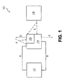
- Fig. 1 illustrates a system for withdrawing permeate from a substrate through a filter and for at least partially cleaning the filter in situ.
- the illustrated system 10 includes a vessel 12 that is configured to contain substrate.
- the composition of the substrate can vary, but the substrate is most frequently a liquid or a slurry of liquid and solid particles.
- System 10 also includes a compartment 14 connected to receive substrates from vessel 12, wherein the flow of substrate from vessel 12 to compartment 14 is indicated at A in Fig. 1, Compartment 14 is also connected to return a portion of received substrate to vessel 12 during normal operation of the system 10. For example, the return flow of substrate from compartment 14 to vessel 12 is indicated at B in Fig. 1. Compartment 14 also includes an opening for discharge from system 10. More specifically, a discharge flow is indicated at C in Fig. 1.
- a filter 16 is positioned at least partially within compartment 14. Filter 16 is connected to withdraw permeate from substrate in compartment 14 during normal operation of the system 10. For example, permeate flow from filter 16 is indicated at D in Fig. 1.
- System 10 also includes a source 18 of cleaning solution.
- Source 18 is connected to introduce cleaning solution into compartment 14 and into contact with filter 16 during cleaning operation of system 10.
- the flow of cleaning solution from source 18 to compartment 14 is indicated at E in Fig. 1.
- the compartment 14 of system 10 facilitates the circulation of substrate through the system 10 during normal operation of the system. More specifically, substrate can be circulated by flow at A from vessel 12 to compartment 14 and by flow at B from compartment 14 to vessel 12. Also, compartment 14 substantially prevents the introduction of cleaning solution, received from source 18, from compartment 14 into contact with substrate contained in vessel 12.
- System 10 illustrated in Fig. 1 is adapted for withdrawing permeate from a substrate through a filter and for at least partially cleaning the filter in situ.
- compartment 14 is provided to at least partially surround filter 16.
- substrate is introduced from vessel 12 into compartment 14 in the form of flow at A.
- Permeate is withdrawn through filter 16 from substrate received in compartment 14 as indicated at D.
- a portion of received substrate is returned from compartment 14 to vessel 12 as indicated at B.
- FIG. 1 Cleaning operation of system 10 is illustrated in Fig. 1 by the use of dotted lines. More specifically, during cleaning operation, flow of substrate into compartment 14 from vessel 12 as indicated at A is prevented. Permeate is returned to compartment 14 and/or through filter 16 as indicated at F. Cleaning solution is introduced at E from source 18 into compartment 14 and/or filter 16 and into contact with external surfaces of filter 16. Cleaning solution may then be drained from compartment 14 as indicated at C, if necessary.
- the method is accomplished while maintaining the filter 16 in situ or in place with respect to compartment 14 and vessel 12.
- filter 16 is maintained in place during the normal operation of system 10 and during cleaning operation of system 10. Filter 16, therefore, need not be removed from compartment 14 to accomplish a deep cleaning.
- system 100 is adapted for withdrawing permeate from substrate through a filter 116 and for at least partially cleaning the filter 116 in situ.
- System 100 includes a vessel 112 configured to contain substrate.
- substrate is introduced into vessel 112 via a feed H'.
- System 100 also includes a compartment 114 connected to receive a substrate from vessel 112.
- substrate is delivered into compartment 114 from vessel 112 by means of a circulating pump 120 that urges substrate toward compartment 114 as indicated at A'.
- Compartment 114 is connected to return a portion of received substrate to vessel 112 during normal operation of the system.
- compartment 114 is positioned at least partially within vessel 112 and has an at least partially open top to permit the overflow of substrate from within compartment 114 into the interior of vessel 112 as indicated at B'.
- a significant portion of substrate received in compartment 114 is intended to return as indicated at B' into vessel 112.
- the majority of substrate received in compartment 114 is returned to vessel 112.
- Compartment 114 also includes an opening for discharge from system 100.
- a valve 126 is provided in order to control discharge flow as indicated at C'.
- a filter 116 is positioned at least partially within, and preferably completely within, compartment 114.
- Filter 116 is connected to withdraw permeate from substrate in compartment 114 during normal operation of the system.
- a permeate pump 122 is connected to filter 116 in order to deliver permeate from filter 116 to a permeate tank 124 as indicated at D',
- a source 118 of cleaning solution is connected to introduce cleaning solution into compartment 114 and into contact with external surfaces of filter 116 during cleaning operation of system 100.
- source 118 delivers cleaning solution as indicated at E' so that it enters compartment 114 (and/or filter 116) for contact with filter 116.
- Compartment 114 facilitates circulation of substrate through system 100 during normal operation of the system and substantially prevents the unintended introduction of cleaning solution from compartment 114 into contact with substrate contained within vessel 112 during cleaning operation.
- Supplemental cleaning features can also be provided in system 100.
- permeate can be returned through filter 116 in order to provide periodic back pulsing of filter 116 in order to facilitate partial cleaning of filter 116.
- agitation air can be introduced proximal to filter 116 in order to cause the filter to vibrate and flex, although the source of such agitation air is not shown in Fig. 2.
- substrate is introduced from vessel 112 into compartment 114 by means of circulating pump 120 as indicated at A'.
- Permeate is withdrawn through filter 116 from substrate received in compartment 114 and is delivered by means of permeate pump 122 to permeate tank 124 as indicated at D'.
- a portion of received substrate is returned from compartment 114 to vessel 112 as indicated at B'.
- the flow at B' is preferably greater than the flow at D'. Most preferably, the ratio of substrate flow at B' to the permeate flow at D' approaches or even exceeds 5:1.
- Cleaning operation of system 100 is indicated by dotted lines.
- flow of substrate into compartment 114 from vessel 112 is prevented (by deactivation of circulating pump 120).
- Permeate is returned to compartment 114 and/or filter 116 from permeate tank 124 as indicated at F'.
- a cleaning solution is introduced from source 118 into compartment 114 (and/or filter 116) and into contact with surfaces of filter 116 as indicated at E'.
- Cleaning solution is subsequently drained from compartment 114 by means of opening valve 126 to induce flow at C'.
- agitation air or other gas can be introduced adjacent to filter 116 as indicated at G'.
- a slurry of biosolids is circulated from a well-mixed reaction area within the vessel 112 through the compartment 114 at a rate equal to several times the permeate withdrawal rate.
- the excess biosolids slurry overflows the compartment 114, thereby returning to the reaction area in the vessel 112.
- the high rate preferred for overflow prevents undue concentration of biosolids in the compartment 114.
- Fresh feed liquid is added to the reactor vessel 112 (at H') at a rate about equal to the rate at which it is being withdrawn as permeate.
- the compartment 114 When periodic chemical cleaning is required, the compartment 114 is isolated and drained of liquid or slurry (by means of valve 126). The compartment 114 is then refilled with stored water previously processed through the membrane (from permeate tank 124) along with the cleaning chemicals. As described, air or other agitation can be applied during the cleaning period as indicated at G'. Following the cleaning period, the cleaning solution can be drained from the compartment 114, if necessary, and the compartment 114 can be refilled with biosolids liquid or slurry. The filter 116 can then be returned to normal operation.
- the filter does not have to be removed from the reactor vessel for cleaning. Accordingly, rigging equipment for filter removal is not required and the plumbing connections for the filter do not have to be disconnected/reconnected.
- System 100 also eliminates the need for an external cleaning tank in which to relocate the filter, thereby saving floor space and the associated plumbing. The time required for cleaning is accordingly reduced. Additionally, the introduction of the compartment, which at least partially surrounds the filter within the vessel, makes it unnecessary to discard or transfer a large volume of biosolids liquid or slurry or to provide a large volume of cleaning solution.
- FIG. 3 a schematic diagram of another embodiment of a system and method according to this invention is illustrated.
- system 200 illustrated in Fig. 2 is adapted for withdrawing permeate from substrate through a filter and for at least partially cleaning the filter in situ.
- system 200 utilizes a vessel 212, a compartment 214, a filter in the form of a membrane cartridge 216, a source of cleaning solution 218, a circulating pump 220, a permeate pump 222, and a permeate tank 224.
- System 200 is provided with a feed source or substrate source 254.
- Feed source 254 is connected to a line 256 through which feed or substrate is introduced into the interior of vessel 212, as indicated in Fig. 3.
- Substrate is delivered into compartment 214 from vessel 212 by means of a circulating pump 220. More specifically, a line 202 extends from the wall of vessel 212 to circulating pump 220, and lines 204 and 206 extend from circulating pump 220 to a location within compartment 214, as will be described.
- a valve 208 is positioned along line 206 in order to control the flow of substrate between circulating pump 220 and compartment 214 through line 206.
- Diffuser pipe 210 Positioned within compartment 214 is a diffuser pipe 210 having a series of openings to permit the flow of substrate from within diffuser pipe 210 into the interior of compartment 214.
- Line 206 is connected to one end portion of diffuser pipe 210 in order to introduce substrate into the interior of diffuser pipe 210.
- Diffuser pipe 210 is preferably a straight pipe that extends substantially horizontally with respect to the bottom surface of compartment 214.
- System 200 also includes means for delivering materials such as waste solids from compartment 214 or for draining compartment 214. More specifically, a line 226 extends from an end of diffuser pipe 210 (an end opposite the end connected to line 206) for the outflow from compartment 214 of waste solids as well as cleaning solutions, as will be described later. Line 226 is connected to a line 228 which, in turn, is connected to a waste solids receptacle 230. A valve 232 positioned along line 228 controls the flow of materials from compartment 214 and diffuser pipe 210 through line 228 to the waste solids receptacle 230.
- a line 234 is also connected to line 226, which is in turn connected to a compartment drain 236.
- a valve 238 positioned along line 234 controls the flow of materials from compartment 214 and diffuser pipe 210 toward compartment drain 236 through line 234.
- Vessel 212 is considered to be a "well mixed tank” because it is provided with a mixing pump that brings about circulation of substrate in vessel 212. The purpose is to keep biosolids suspended in the substrate during operation of system 200. More specifically, a line 240 extends from the wall of vessel 212 to deliver substrate from vessel 212 to a mixing pump 242. The mixing pump 242 urges substrate along a line 244 from line 240 so that it enters a mixer such as mixing eductor 248.
- Mixing eductor 248 can be provided in the form of a module such as a pod with radially oriented nozzles such as the embodiment shown in Fig. 3.
- mixing eductor 248 can be provided in the form of a pipe such as a straight pipe that extends at least partially across the diameter of vessel 212 with a series of outlet openings.
- a straight pipe as opposed to a pod may be preferred for larger tanks that may have an extensive diameter.
- Other forms of an inlet such as eductor 248 are known in the art and can be substituted for the form illustrated in Fig. 3. Also known in the art are other forms of mixing with or without the use of air or other gases.
- System 200 also includes a source 250 of mix air or other gas that travels along line 252, enters mixing eductor 248, and is introduced into the interior of vessel 212.
- the introduction of mix air into mixing eductor 248 for mixing with substrate creates agitation, which encourages the mixing of the substrate and the suspension of the biosolids within vessel 212.
- the introduction of air, if air is used, also provides a source of oxygen to support the biological activity that occurs within vessel 212.
- System 200 also includes a membrane cartridge 216, which extends at least partially, and preferably completely, within the interior of compartment 214.
- the membrane cartridge of this embodiment is a submersible membrane filter having a series of hollow fiber membranes extending between manifolds. Permeate is extracted through membrane cartridge 216 by permeation through the walls of the hollow fiber membranes, transportation of the permeate through the membranes to the connected manifolds, and removal of permeate through a reduced-pressure piping system.
- membrane cartridge 216 of system 200 has a bottom manifold 264, a top manifold 266, and a series of membranes such as hollow fiber membranes 268 extending substantially vertically between bottom manifold 264 and top manifold 266. Fibers 268 provide a barrier through which permeate is drawn during normal operation of system 200 in order to extract permeate from the substrate.
- System 200 also includes a membrane air or other gas source 258 that introduces air or other gas into a line 260 so that it can be transported to an air manifold 262 that is positioned adjacent to or at least partially within membrane cartridge 216.
- the air manifold 262 includes air outlets or nozzles (not shown) which permit the flow of air bubbles adjacent to the membranes 268 of membrane cartridge 216. Such air bubbles can help to reduce the rate at which a film of bio-mass is formed on the outer surfaces of the membranes 268.
- Air from membrane air source 258 also tends to encourage the mixing of substrate (and cleaning solution, as will be described) within compartment 214.
- a pair of lines 270, 272 extend upwardly from membrane cartridge 216, wherein line 270 is connected to permit the flow of permeate upwardly from bottom manifold 264 and line 272 is connected to permit the flow of permeate upwardly from top manifold 266.
- Lines 270 and 272 are connected to a line 274, and a valve 276 is provided along line 274 in order to control the flow of permeate through line 274.
- line 274 Connected to line 274 is a line 278, which is in turn connected to an air vent 280 for the ventilation of undissolved air from the permeate that may have been introduced into the permeate from an outside source such as membrane air source 258. Also connected to line 274 is a line 282 that extends upwardly, and a permeate pump 222 is connected along line 282 in order to urge the flow of permeate through line 282.
- permeate pump 222 As an alternative to the use of permeate pump 222, it has been discovered that gravity flow can be employed to transfer permeate from membrane cartridge 216 to a permeate tank 224 (or directly to a discharge). More specifically, if the elevation of the membrane cartridge 216 is maintained above that of the permeate in permeate tank 224, then permeate will flow from the membrane cartridge 216 to the permeate tank 224 by action of atmospheric pressure and a siphon effect.
- the configuration of compartment 214 and membrane cartridge 216 in the embodiment illustrated in Fig. 3 makes it possible, therefore, to eliminate permeate pump 222 and the energy required to run the pump if at least a portion of the permeate tank 224 is repositioned below the filter.
- a pump may be required to return permeate from permeate tank 224 to membrane cartridge 216 if the permeate tank 224 is positioned at an elevation below the filter. Such a pump would run less than permeate pump 222 because of the preferred intermittent nature of the "pulsed cleaning" operation (as described later) as compared to the substantially continuous running of permeate pump 222 during the cleaning operation.
- Line 284 Connected to line 282 is a line 284 on which a valve 286 is provided to control the flow through line 284.
- Line 284 is, in turn, connected to a permeate tank 224, which is adapted to contain and collect permeate extracted from the substrate in vessel 212. Permeate within permeate tank 224 overflows into a baffle 225 from which the permeate or effluent is removed from the system 200 for use or for further processing.
- a line 288 Connected to the bottom portion of permeate tank 224 is a line 288 for delivering permeate toward line 282.
- a valve 290 is provided along line 288 to control the flow of permeate from permeate tank 224 to line 282.
- a line 292 Also connected to line 282 is a line 292 for the flow of permeate from line 282 to lines 294 and 296.
- Line 294 is provided with a valve 295 in order to control the flow of permeate therethrough, and line 296 is provided with a valve 297 to control the flow of permeate therethrough.
- Line 294 is connected between line 292 and line 274.
- line 296 is connected between line 292 and compartment 214 for the delivery of flow into compartment 214.
- the source of cleaning solution 218 is connected to line 292 by means of a line 298 that extends between source 218 and line 292 in order to permit the flow of cleaning solution from source 218 to the remainder of system 200.
- a line 298 that extends between source 218 and line 292 in order to permit the flow of cleaning solution from source 218 to the remainder of system 200.
- chlorine solutions are preferred.
- system 200 will now be described with reference to Fig. 3. Three general operations of the system will be described in terms of "normal operation” of system 200 during which permeate is extracted from the substrate, a “pulsed cleaning” of system 200 which preferably occurs periodically during normal operation, and a “deep cleaning” of system 200 which preferably occurs during an interruption of normal operation.
- substrate is fed into vessel 212, circulated to compartment 214, and permeate is removed through membrane cartridge 216 during normal operation of system 200.
- Permeate is delivered to permeate tank 224 or, alternatively, directly to discharge.
- substrate is mixed in vessel 212 to maintain a well mixed tank.
- pulsed cleaning which preferably occurs periodically during normal operation of system 200, permeate is pulsed back into membrane cartridge 216 in a reverse flow direction (by pump or by atmospheric pressure) in order to help reduce the accumulation of biosolids or other organic or inorganic foulants on the surfaces of the fibers 268 of membrane cartridge 216.
- a pulsed cleaning operation can be conducted at timed intervals for a short duration. For example, and for purposes of illustration only, pulsed cleaning can be conducted twice per hour, each time for a pre-determined duration of about one minute. Other intervals (more or less frequent) and durations (longer or shorter) are of course contemplated.
- substrate contained in compartment 214 is drained and replaced with a cleaning solution for a predetermined period of time in order to bring about a chemical cleaning of the fibers 268 of membrane cartridge 216. Thereafter, the cleaning solution can be drained and replaced with substrate from vessel 212, if necessary, to return system 200 to normal operation.
- circulating pump 220 is actuated and valve 208 is opened so that substrate can be urged from vessel 212 into diffuser pipe 210 for introduction into the interior of compartment 214.
- Valve 232 on line 228 can be periodically opened during normal operation in order to extract some of the biosolids that may otherwise accumulate within compartment 214.
- valve 238 on line 234 is closed in order to prevent the flow of substrate from compartment 214 toward compartment drain 236.
- System 200 is designed so that the flow rate of substrate from vessel 212 into compartment 214 exceeds the flow rate of permeate from membrane cartridge 216 for removal from system 200. Accordingly, the flow rate into compartment 214 of substrate through diffuser pipe 210 is greater than the flow rate of permeate out of compartment 214. There will therefore be overflow of substrate over the upper edge or lip of compartment 214 into vessel 212.
- the flow rate of permeate from membrane cartridge 216 is "X”
- the flow rate of substrate from vessel 212 into compartment 214 is "6X”
- valve 232 it would be expected that the overflow of substrate from compartment 214 back into vessel 212 would actually be slightly less than 5X.
- overflow of excess substrate from the compartment back into vessel confers several benefits. Primarily, such overflow provides additional circulation to system 200, thereby maintaining a more uniform suspension of bio-mass in the substrate.
- the overflow also helps to maintain the membrane cartridge within substrate in the compartment so that it remains completely submerged.
- the overflow also creates a flow pattern adjacent to the membrane cartridge so as to reduce the accumulation of bio-mass in the compartment and on the membrane surfaces.
- permeate pump 222 is actuated and valves 276 and 286 are opened in order to draw permeate through the boundary provided by fibers 268, into bottom and top manifolds 264 and 266, through lines 270 and 272 to line 274, through line 282 and line 284, for delivery into the interior of permeate tank 224.
- permeate pump 222 need not be used if the elevations of the fibers 268 and permeate tank 224 are adjusted such that atmospheric pressure causes the permeate to flow from the fibers to the tank.
- Permeate then exits permeate tank 224 through baffled area 225 for use or for further processing.
- permeate can be delivered directly to a discharge when the permeate tank is filled or it can completely bypass the permeate tank.
- valves 290, 295, and 297 are closed (except as indicated below during pulsed cleaning) in order to prevent the return of permeate toward membrane cartridge 216.
- feed of substrate is introduced from feed source 254, through line 256, and into vessel 212.
- mixing pump 242 is actuated, either periodically or continuously, in order to transfer substrate from vessel 212, through lines 240 and 244, and into mixing eductor 248.
- mix air is introduced from a source 250 of mix air or other gas, through line 252, and into mixing eductor 248 to mix with the substrate.
- the nozzles on mixing eductor 248 deliver a mixture of substrate and mix air from mixing eductor 248 back into vessel 212 in order to maintain a well mixed tank.
- Membrane air is also introduced during normal operation of system 200 from membrane air source 258, through line 260, through air manifold 262, and into compartment 214 adjacent to the fibers 268 of membrane cartridge 216. Membrane air thus introduced helps to provide agitation in the substrate adjacent to the fibers in order to reduce the tendency of bio-mass to settle in the form of a film on the surface of the fibers. Also during normal operation of system 200, air is vented from line 274, through line 278, to air vent 280 in order to discharge undissolved air from the system.
- pulsed cleaning is preferably conducted at predetermined intervals and for predetermined durations throughout the normal operation of system 200. More specifically, at the designated intervals and for the designated duration, valves 290 and 295 are opened, and valves 276 and 286 are closed, so that permeate pump 222 (or atmospheric pressure as described above) can urge permeate from tank 224; through lines 288, 282, 292, 294, 270, and 272; and into manifolds 264 and 266, for flow into fibers 268. This reverse flow causes permeate to flow in the opposite direction of normal operation through the fiber walls in such a manner as to reduce the build up of bio-mass on the outer walls of the fibers. As permeate is introduced along line 292, it is preferably mixed with cleaning solution introduced from source 218 along line 298.
- Valves 276, 286, and 295 are closed, and permeate pump 222 is actuated, in order to deliver permeate from permeate tank 224; through lines 288, 282, 292, and 296; and into compartment 214.
- Cleaning solution is simultaneously delivered from source 218 along line 298 to mix with the introduced permeate in line 292.
- Compartment 214 is filled with a mixture of permeate and cleaning solution until it preferably reaches a height above the top manifold 266 of membrane cartridge 216 (so that the membrane cartridge will be fully submerged in the permeate/cleaning solution mixture) but below the upper lip of compartment 214 (so that the permeate/cleaning solution mixture will not flow over the edge of the compartment into the interior of vessel 212 for mixture with the substrate that is still within the interior of vessel 212). Accordingly, the substrate within vessel 212 will not be contacted by a substantial amount of cleaning solution and, therefore, the cleaning solution will be prevented from attacking the bio-mass in the substrate, which could otherwise compromise the ability of the bio-mass to treat the substrate.
- the membrane cartridge 216 is then "soaked” in the cleaning solution for a predetermined period of time in order to eliminate or reduce the amount of bio-mass that may have accumulated on the surfaces of the fibers 268 of the membrane cartridge 216.
- durations may be selected depending on the particular constituents of the substrate and bio-mass and other factors, the duration of the cleaning operation is preferably several hours and preferably as long as four hours or longer.
- Such "deep cleaning" may be advantageously performed once per month of normal operation or at more or less frequent intervals depending on the needs of the system and the rate at which a bio-film is generated on the fibers.
- membrane air can optionally be added from membrane air source 258 along line 260 and through air manifold 262 in order to provide additional agitation for the removal of bio-mass from the surface of the fibers 268.
- the pulsed cleaning operation described previously can be performed during the cleaning operation in order to introduce permeate (with or without cleaning solution) into the interior of fibers 268 for reverse flow through membrane cartridge 216.
- permeate with or without cleaning solution
- Such a combination of pulsed cleaning and deep cleaning can be advantageous to accelerate the elimination of bio-mass from the fiber surfaces.
- valve 238 can be opened so that cleaning solution can be drained from compartment 214 through diffuser pipe 210, lines 226 and 234, for delivery to compartment drain 236.
- the normal operation of system 200 (described above) can be restarted by once again introducing substrate from vessel 212 into compartment 214.
- the cleaning solution is neutralized or consumed during the duration of the cleaning operation, then it is possible to proceed directly to normal operation of system 200 without draining compartment 214.
- substrate can simply be introduced into compartment 214 and into contact with the cleaning solution to bring about normal operation of system 200.
- the spent cleaning solution is then diluted in the substrate for mixture in compartment 214 and vessel 212.
Landscapes
- Chemical & Material Sciences (AREA)
- Chemical Kinetics & Catalysis (AREA)
- Engineering & Computer Science (AREA)
- Water Supply & Treatment (AREA)
- Life Sciences & Earth Sciences (AREA)
- Microbiology (AREA)
- Biodiversity & Conservation Biology (AREA)
- Hydrology & Water Resources (AREA)
- Environmental & Geological Engineering (AREA)
- Organic Chemistry (AREA)
- Separation Using Semi-Permeable Membranes (AREA)
- Cleaning Or Drying Semiconductors (AREA)
- Electrical Discharge Machining, Electrochemical Machining, And Combined Machining (AREA)
- Weting (AREA)
Abstract
Description
- This invention relates to a system for withdrawing permeate from a substrate through a filter. More particularly, this invention relates to a system adapted for withdrawing permeate from a substrate through a filter and for cleaning the filter in situ. A method is also provided.
- Filtration systems provide barriers in order to allow permeate to be drawn off from a substrate through the filter while concentrate is left behind. For example, filtration systems have been used as barriers to retain biosolids in biological reactors. In such filtration systems, membranes have been proposed as the barrier. Such membranes can be provided in the form of hollow fibers; tubes, or rolls, for example.
- For the purpose of illustration, leachate treatment systems for wastewater treatment applications may use a membrane separator in order to separate feed into permeate and bio-mass. Such systems are available, for example, under the trademark ZEEWEED from Zenon Environmental Inc. of Ontario, Canada. The ZEEWEED system uses a submersible membrane cassette to bring about bio-oxidation to oxidize organic matter in the feed. Membranes are used to retain bacteria in the system for essentially complete oxidation and to provide high effluent quality.
- It has been recognized that it is important to keep membranes used in such systems "clean" because, after some period of use, a fouling film or "bio-film" can form on the membrane, thereby reducing the flow of permeate through the membrane. A buildup, whether organic or inorganic, may form on the membrane's outer surface, inner surface, and/or in the membrane's pores that extend through the membrane's wall. Such a buildup on the membrane has, therefore, been recognized to decrease the performance of the membrane as a viable filter.
- U.S. Patent No. 5,403,479, issued to Smith et al. ("In Situ Cleaning System for Fouled Membranes") provides ample background as to the nature and extent of the fouling problem that tends to plague the bio-filtration industry.
- As one possible solution to the problem of membrane fouling, Smith et al. proposed in the '479 patent a cleaning system for substantially restoring transmembrane flux in fouled, porous/semipermeable microfiltration or ultrafiltration membranes used to recover purified water from contaminated or "dirty" water. Specifically, Smith et al. proposed cleaning a module containing a membrane, without draining feed from the module, by introducing a chosen cleaning fluid into the permeate and recycling it through the lumens of hollow fiber membranes at low pressure not exceeding the bubble point of the fiber. The process proposed by Smith et al. in the '479 patent cleans from the permeate side of the membrane; that is, through the lumens of the hollow fibers.
- U.S. Patent No. 5,248,424, issued to Cote et al. ("Frameless Array of Hollow Fiber Membranes and Method of Maintaining Clean Fiber Surfaces While Filtering a Substrate to Withdraw a Permeate") proposed another approach for maintaining the performance of filtration membranes; more specifically, a frameless array of hollow fibers. Cote et al. proposed in the '424 patent a system to reduce the build-up of growing microbes or the deposits of inanimate particles upon the surfaces of fibers kept awash in bubbles of a fiber-cleansing gas ("scrubbing gas"), particularly an oxygen-containing gas ("air-scrubbed"). The build-up is essentially naked when the fibers are buoyantly freely swayable in a frameless array submerged in a substrate through which the bubbles rise with sufficient physical force of impact to keep the fibers essentially free of deleterious deposits. Similar solutions were proposed by Mahendran et al. in U.S. Patent No. 5,639,373 ("Vertical Skein of Hollow Fiber Membranes and Method of Maintaining Clean Fiber Surfaces While Filtering a Substrate to Withdraw a Permeate") and by Henshaw et al. in U.S. Patent No. 5,783,083 ("Vertical Cylindrical Skein of Hollow Fiber Membranes and Method of Maintaining Clean Fiber Surfaces").
- In International Publication No. WO 98/37950 ("Portable Reverse Osmosis Unit for Producing Drinking Water"), Daly et al. proposed a method and apparatus for producing drinking water from impure water wherein hollow tubular membranes of the system are periodically back flushed with retentate by directing the retentate to the inside surfaces of the membranes and by passing the retentate through the membranes, thereby dislodging particles from the outside surfaces. When chemical cleaning of the membranes is required in the method and apparatus proposed in the '950 publication, cleaning solution is pumped from a tank into the membranes.
- In Australian Patent Application No. AU 9676300 (corresponding to International Publication No. WO 97/18887), Cote et al. described a method for cleaning immersed membranes in situ, wherein effluent contained in the tank is at least partially emptied in order to expose the membranes to the air, and cleaning solutions are passed through the pores of the membranes along a flow path opposite to the filtration flow of the effluent by delivering cleaning solution to the permeate side of the membranes. A shut-off valve is opened in order to drain off effluent from a treatment tank. Cleaning solution is then introduced into the membranes from a reservoir. In another embodiment, four tanks are supplied with effluent. When one wishes to clean the membranes in one of the tanks, the contents of the selected tank are transferred into the other tanks. Cleaning solutions are fed into the membranes of the empty, selected tank from reservoirs.
- Although significant effort has been expended to resolve this recognized problem of fouling, improvements regarding the "cleaning" of filtration systems such as those that employ membranes are still in demand, whether the membranes are provided in the form of hollow fibers, tubes, rolls, or other membrane configurations. Specifically, despite these significant advances in the art of filter cleaning, and despite the purported ability of such proposed systems to prolong the throughput rate of the membranes used as filters, it has been discovered that, in some instances, the membranes must eventually be removed from the process for a thorough cleaning such as a deep chemical cleaning. The need to remove a filter from a system such as a biological reactor is of course time consuming, expensive, labor intensive, and generally undesirable. Moreover, it often requires that the system be at least partially shut down during the cleaning process while the filter is removed.
- For example, it is undesirable to remove a submersible membrane unit from a biological reactor and to move the submersible membrane unit to a separate tank for cleaning. Membrane assemblies can be quite large and quite heavy. Also, in the case of an industrial biological reaction system, the biological reactor vessels in which membrane assemblies are used can be quite tall, thereby requiring expensive and cumbersome rigging equipment for removal. Furthermore, the various "plumbing" connections to such membrane assemblies must be disconnected and subsequently reconnected in order to bring about membrane assembly removal and replacement, respectively. It will also be understood that over-head clearance may not be available for removing such membrane assemblies easily, and when such systems are removed, the process of doing so can create quite a mess. Also, external tanks dedicated to separate cleaning operations for off-line cleaning procedures require significant floor or ground space and numerous "plumbing" connections.
- DE 40 37 329 A1 discloses a process for treating waste waters from glass grinding shops in which the waste waters, which are collected in a suction tank, are circulated through an ultra filtration module in cross flow with the flow direction being reversed periodically. The ultra filtration module may be cleaned from time to time by moving an object with a rough surface over the ultra filtration membrane, e.g., balls of felt or cork or a sponge ball. The sponge ball may be introduced and removed from the ultra filtration module via sponge ball locks.
- DE-A-4340529 discloses an ultra-filtration device for the treatment of pollutant-containing aqueous solutions. Fouling of a reverse osmosis filtration membrane is prevented by controlled reversal of flow within the membrane.
- Accordingly, the need remains for an improved system for withdrawing permeate from a substrate through a filter and for cleaning the filter in situ. A corresponding method is also needed.
- In accordance with a first aspect of the present invention therefore there is provided apparatus as claimed in claim 1 below.
- In the system according to this invention, the compartment facilitates circulation of substrate during normal operation of the system. The compartment also makes it possible to substantially prevent the introduction of cleaning solutions from the compartment into contact with substrate contained in the vessel during the cleaning operation of the system. Accordingly, the system of this invention is adapted for withdrawing permeate from a substrate through the filter and for cleaning the filter in situ in order to avoid the need for periodic removal of the filter.
- In a second aspect of the present invention there is provided a method as claimed in
claim 16 below. - Features of the claimed invention will now be described with reference to the figures. It will be appreciated that the scope of this invention is not limited to the embodiments selected or illustrated in figures 2 or 3 and that the scope of the invention is separately defined by the appended claims. It will also be appreciated that the figures are not drawn to any particular proportion or scale.
- Fig. 1 is a block diagram of an embodiment of a system and method not according to the claims of this invention, but which provides background information.
- Fig. 2 is a schematic diagram of one embodiment of a system and method according to the claims of this invention.
- Fig. 3 is a schematic diagram of another embodiment of a system and method according to the claims of this invention.
- Fig. 1 illustrates a system for withdrawing permeate from a substrate through a filter and for at least partially cleaning the filter in situ. The illustrated
system 10 includes avessel 12 that is configured to contain substrate. The composition of the substrate can vary, but the substrate is most frequently a liquid or a slurry of liquid and solid particles. -
System 10 also includes acompartment 14 connected to receive substrates fromvessel 12, wherein the flow of substrate fromvessel 12 tocompartment 14 is indicated at A in Fig. 1,Compartment 14 is also connected to return a portion of received substrate tovessel 12 during normal operation of thesystem 10. For example, the return flow of substrate fromcompartment 14 tovessel 12 is indicated at B in Fig. 1.Compartment 14 also includes an opening for discharge fromsystem 10. More specifically, a discharge flow is indicated at C in Fig. 1. - A
filter 16 is positioned at least partially withincompartment 14.Filter 16 is connected to withdraw permeate from substrate incompartment 14 during normal operation of thesystem 10. For example, permeate flow fromfilter 16 is indicated at D in Fig. 1. -
System 10 also includes asource 18 of cleaning solution.Source 18 is connected to introduce cleaning solution intocompartment 14 and into contact withfilter 16 during cleaning operation ofsystem 10. For example, the flow of cleaning solution fromsource 18 tocompartment 14 is indicated at E in Fig. 1. - The
compartment 14 ofsystem 10 facilitates the circulation of substrate through thesystem 10 during normal operation of the system. More specifically, substrate can be circulated by flow at A fromvessel 12 tocompartment 14 and by flow at B fromcompartment 14 tovessel 12. Also,compartment 14 substantially prevents the introduction of cleaning solution, received fromsource 18, fromcompartment 14 into contact with substrate contained invessel 12. -
System 10 illustrated in Fig. 1 is adapted for withdrawing permeate from a substrate through a filter and for at least partially cleaning the filter in situ. In use,compartment 14 is provided to at least partially surroundfilter 16. During normal operation ofsystem 10, substrate is introduced fromvessel 12 intocompartment 14 in the form of flow at A. Permeate is withdrawn throughfilter 16 from substrate received incompartment 14 as indicated at D. Also during normal operation, a portion of received substrate is returned fromcompartment 14 tovessel 12 as indicated at B. - Cleaning operation of
system 10 is illustrated in Fig. 1 by the use of dotted lines. More specifically, during cleaning operation, flow of substrate intocompartment 14 fromvessel 12 as indicated at A is prevented. Permeate is returned tocompartment 14 and/or throughfilter 16 as indicated at F. Cleaning solution is introduced at E fromsource 18 intocompartment 14 and/or filter 16 and into contact with external surfaces offilter 16. Cleaning solution may then be drained fromcompartment 14 as indicated at C, if necessary. - The method is accomplished while maintaining the
filter 16 in situ or in place with respect tocompartment 14 andvessel 12. In other words, filter 16 is maintained in place during the normal operation ofsystem 10 and during cleaning operation ofsystem 10.Filter 16, therefore, need not be removed fromcompartment 14 to accomplish a deep cleaning. - Referring now to Fig. 2, a schematic diagram of an embodiment of a system and method according to this invention is provided. Like
system 10,system 100 is adapted for withdrawing permeate from substrate through afilter 116 and for at least partially cleaning thefilter 116 in situ. -
System 100 includes avessel 112 configured to contain substrate. In this embodiment, substrate is introduced intovessel 112 via a feed H'.System 100 also includes acompartment 114 connected to receive a substrate fromvessel 112. In this embodiment, substrate is delivered intocompartment 114 fromvessel 112 by means of a circulatingpump 120 that urges substrate towardcompartment 114 as indicated at A'.Compartment 114 is connected to return a portion of received substrate tovessel 112 during normal operation of the system. - In this embodiment,
compartment 114 is positioned at least partially withinvessel 112 and has an at least partially open top to permit the overflow of substrate from withincompartment 114 into the interior ofvessel 112 as indicated at B'. In order to prevent or reduce the tendency for concentration of biosolids incompartment 114, a significant portion of substrate received incompartment 114 is intended to return as indicated at B' intovessel 112. Preferably, the majority of substrate received incompartment 114 is returned tovessel 112.Compartment 114 also includes an opening for discharge fromsystem 100. In this embodiment, avalve 126 is provided in order to control discharge flow as indicated at C'. - A
filter 116 is positioned at least partially within, and preferably completely within,compartment 114.Filter 116 is connected to withdraw permeate from substrate incompartment 114 during normal operation of the system. In this embodiment, apermeate pump 122 is connected to filter 116 in order to deliver permeate fromfilter 116 to apermeate tank 124 as indicated at D', - A
source 118 of cleaning solution is connected to introduce cleaning solution intocompartment 114 and into contact with external surfaces offilter 116 during cleaning operation ofsystem 100. In this embodiment,source 118 delivers cleaning solution as indicated at E' so that it enters compartment 114 (and/or filter 116) for contact withfilter 116. -
Compartment 114 facilitates circulation of substrate throughsystem 100 during normal operation of the system and substantially prevents the unintended introduction of cleaning solution fromcompartment 114 into contact with substrate contained withinvessel 112 during cleaning operation. - Supplemental cleaning features can also be provided in
system 100. For example, permeate can be returned throughfilter 116 in order to provide periodic back pulsing offilter 116 in order to facilitate partial cleaning offilter 116. Also, agitation air can be introduced proximal to filter 116 in order to cause the filter to vibrate and flex, although the source of such agitation air is not shown in Fig. 2. - During use of
system 100, and during normal operation, substrate is introduced fromvessel 112 intocompartment 114 by means of circulatingpump 120 as indicated at A'. Permeate is withdrawn throughfilter 116 from substrate received incompartment 114 and is delivered by means ofpermeate pump 122 to permeatetank 124 as indicated at D'. A portion of received substrate is returned fromcompartment 114 tovessel 112 as indicated at B'. The flow at B' is preferably greater than the flow at D'. Most preferably, the ratio of substrate flow at B' to the permeate flow at D' approaches or even exceeds 5:1. - Cleaning operation of
system 100 is indicated by dotted lines. During cleaning operation ofsystem 100, flow of substrate intocompartment 114 fromvessel 112 is prevented (by deactivation of circulating pump 120). Permeate is returned tocompartment 114 and/or filter 116 frompermeate tank 124 as indicated at F'. A cleaning solution is introduced fromsource 118 into compartment 114 (and/or filter 116) and into contact with surfaces offilter 116 as indicated at E'. Cleaning solution is subsequently drained fromcompartment 114 by means of openingvalve 126 to induce flow at C'. In order to assist in the cleaning operation, agitation air or other gas can be introduced adjacent to filter 116 as indicated at G'. - In the invention embodiment illustrated in Fig. 2, a slurry of biosolids is circulated from a well-mixed reaction area within the
vessel 112 through thecompartment 114 at a rate equal to several times the permeate withdrawal rate. The excess biosolids slurry overflows thecompartment 114, thereby returning to the reaction area in thevessel 112. The high rate preferred for overflow prevents undue concentration of biosolids in thecompartment 114. Fresh feed liquid is added to the reactor vessel 112 (at H') at a rate about equal to the rate at which it is being withdrawn as permeate. - When periodic chemical cleaning is required, the
compartment 114 is isolated and drained of liquid or slurry (by means of valve 126). Thecompartment 114 is then refilled with stored water previously processed through the membrane (from permeate tank 124) along with the cleaning chemicals. As described, air or other agitation can be applied during the cleaning period as indicated at G'. Following the cleaning period, the cleaning solution can be drained from thecompartment 114, if necessary, and thecompartment 114 can be refilled with biosolids liquid or slurry. Thefilter 116 can then be returned to normal operation. - This embodiment of the invention confers several significant benefits. Specifically, the filter does not have to be removed from the reactor vessel for cleaning. Accordingly, rigging equipment for filter removal is not required and the plumbing connections for the filter do not have to be disconnected/reconnected.
System 100 also eliminates the need for an external cleaning tank in which to relocate the filter, thereby saving floor space and the associated plumbing. The time required for cleaning is accordingly reduced. Additionally, the introduction of the compartment, which at least partially surrounds the filter within the vessel, makes it unnecessary to discard or transfer a large volume of biosolids liquid or slurry or to provide a large volume of cleaning solution. - Referring now to Fig. 3, a schematic diagram of another embodiment of a system and method according to this invention is illustrated. Like
systems system 200 illustrated in Fig. 2 is adapted for withdrawing permeate from substrate through a filter and for at least partially cleaning the filter in situ. Also, likesystem 100,system 200 utilizes avessel 212, acompartment 214, a filter in the form of amembrane cartridge 216, a source of cleaningsolution 218, a circulatingpump 220, apermeate pump 222, and apermeate tank 224. -
System 200 is provided with a feed source orsubstrate source 254. Feedsource 254 is connected to aline 256 through which feed or substrate is introduced into the interior ofvessel 212, as indicated in Fig. 3. Substrate is delivered intocompartment 214 fromvessel 212 by means of a circulatingpump 220. More specifically, aline 202 extends from the wall ofvessel 212 to circulatingpump 220, andlines pump 220 to a location withincompartment 214, as will be described. Avalve 208 is positioned alongline 206 in order to control the flow of substrate between circulatingpump 220 andcompartment 214 throughline 206. - Positioned within
compartment 214 is adiffuser pipe 210 having a series of openings to permit the flow of substrate from withindiffuser pipe 210 into the interior ofcompartment 214.Line 206 is connected to one end portion ofdiffuser pipe 210 in order to introduce substrate into the interior ofdiffuser pipe 210.Diffuser pipe 210 is preferably a straight pipe that extends substantially horizontally with respect to the bottom surface ofcompartment 214. -
System 200 also includes means for delivering materials such as waste solids fromcompartment 214 or for drainingcompartment 214. More specifically, aline 226 extends from an end of diffuser pipe 210 (an end opposite the end connected to line 206) for the outflow fromcompartment 214 of waste solids as well as cleaning solutions, as will be described later.Line 226 is connected to aline 228 which, in turn, is connected to awaste solids receptacle 230. Avalve 232 positioned alongline 228 controls the flow of materials fromcompartment 214 anddiffuser pipe 210 throughline 228 to thewaste solids receptacle 230. - A
line 234 is also connected toline 226, which is in turn connected to acompartment drain 236. Avalve 238 positioned alongline 234 controls the flow of materials fromcompartment 214 anddiffuser pipe 210 towardcompartment drain 236 throughline 234. -
Vessel 212 is considered to be a "well mixed tank" because it is provided with a mixing pump that brings about circulation of substrate invessel 212. The purpose is to keep biosolids suspended in the substrate during operation ofsystem 200. More specifically, aline 240 extends from the wall ofvessel 212 to deliver substrate fromvessel 212 to amixing pump 242. The mixingpump 242 urges substrate along aline 244 fromline 240 so that it enters a mixer such as mixingeductor 248. Mixingeductor 248 can be provided in the form of a module such as a pod with radially oriented nozzles such as the embodiment shown in Fig. 3. Alternatively, mixingeductor 248 can be provided in the form of a pipe such as a straight pipe that extends at least partially across the diameter ofvessel 212 with a series of outlet openings. The use of a straight pipe as opposed to a pod may be preferred for larger tanks that may have an extensive diameter. Other forms of an inlet such aseductor 248 are known in the art and can be substituted for the form illustrated in Fig. 3. Also known in the art are other forms of mixing with or without the use of air or other gases. -
System 200 also includes asource 250 of mix air or other gas that travels alongline 252, enters mixingeductor 248, and is introduced into the interior ofvessel 212. The introduction of mix air into mixingeductor 248 for mixing with substrate creates agitation, which encourages the mixing of the substrate and the suspension of the biosolids withinvessel 212. The introduction of air, if air is used, also provides a source of oxygen to support the biological activity that occurs withinvessel 212. -
System 200 also includes amembrane cartridge 216, which extends at least partially, and preferably completely, within the interior ofcompartment 214. The membrane cartridge of this embodiment is a submersible membrane filter having a series of hollow fiber membranes extending between manifolds. Permeate is extracted throughmembrane cartridge 216 by permeation through the walls of the hollow fiber membranes, transportation of the permeate through the membranes to the connected manifolds, and removal of permeate through a reduced-pressure piping system. More specifically,membrane cartridge 216 ofsystem 200 has abottom manifold 264, atop manifold 266, and a series of membranes such ashollow fiber membranes 268 extending substantially vertically betweenbottom manifold 264 andtop manifold 266.Fibers 268 provide a barrier through which permeate is drawn during normal operation ofsystem 200 in order to extract permeate from the substrate. - As will be understood, when a vacuum is drawn at the interior of the
fibers 268, permeate is drawn through the walls of thehollow fibers 268 and into the interior of thehollow fibers 268 so that the permeate can be extracted via bottom andtop manifolds system 200. In other words, by creating a pressure differential across the thickness of the walls ofhollow fibers 268, wherein the pressure on the outside of thefibers 268 is greater than the pressure within the interior offibers 268, permeate is caused to flow through pores in the walls of thehollow fibers 268 and into the interior thereof for extraction fromsystem 200. Biosolids such as bio-mass are blocked by thefibers 268 and remain in the compartment. -
System 200 also includes a membrane air orother gas source 258 that introduces air or other gas into aline 260 so that it can be transported to anair manifold 262 that is positioned adjacent to or at least partially withinmembrane cartridge 216. Theair manifold 262 includes air outlets or nozzles (not shown) which permit the flow of air bubbles adjacent to themembranes 268 ofmembrane cartridge 216. Such air bubbles can help to reduce the rate at which a film of bio-mass is formed on the outer surfaces of themembranes 268. Air frommembrane air source 258 also tends to encourage the mixing of substrate (and cleaning solution, as will be described) withincompartment 214. - Still referring to Fig. 3, a pair of
lines 270, 272 extend upwardly frommembrane cartridge 216, wherein line 270 is connected to permit the flow of permeate upwardly frombottom manifold 264 andline 272 is connected to permit the flow of permeate upwardly fromtop manifold 266.Lines 270 and 272 are connected to aline 274, and avalve 276 is provided alongline 274 in order to control the flow of permeate throughline 274. - Connected to
line 274 is aline 278, which is in turn connected to anair vent 280 for the ventilation of undissolved air from the permeate that may have been introduced into the permeate from an outside source such asmembrane air source 258. Also connected toline 274 is aline 282 that extends upwardly, and apermeate pump 222 is connected alongline 282 in order to urge the flow of permeate throughline 282. - As an alternative to the use of
permeate pump 222, it has been discovered that gravity flow can be employed to transfer permeate frommembrane cartridge 216 to a permeate tank 224 (or directly to a discharge). More specifically, if the elevation of themembrane cartridge 216 is maintained above that of the permeate inpermeate tank 224, then permeate will flow from themembrane cartridge 216 to thepermeate tank 224 by action of atmospheric pressure and a siphon effect. The configuration ofcompartment 214 andmembrane cartridge 216 in the embodiment illustrated in Fig. 3 makes it possible, therefore, to eliminate permeate pump 222 and the energy required to run the pump if at least a portion of thepermeate tank 224 is repositioned below the filter. - If "pulsed cleaning" is performed (as described later), it will be appreciated that a pump may be required to return permeate from
permeate tank 224 tomembrane cartridge 216 if thepermeate tank 224 is positioned at an elevation below the filter. Such a pump would run less thanpermeate pump 222 because of the preferred intermittent nature of the "pulsed cleaning" operation (as described later) as compared to the substantially continuous running ofpermeate pump 222 during the cleaning operation. - Connected to
line 282 is aline 284 on which avalve 286 is provided to control the flow throughline 284.Line 284 is, in turn, connected to apermeate tank 224, which is adapted to contain and collect permeate extracted from the substrate invessel 212. Permeate withinpermeate tank 224 overflows into abaffle 225 from which the permeate or effluent is removed from thesystem 200 for use or for further processing. - Connected to the bottom portion of
permeate tank 224 is aline 288 for delivering permeate towardline 282. Avalve 290 is provided alongline 288 to control the flow of permeate frompermeate tank 224 toline 282. Also connected toline 282 is aline 292 for the flow of permeate fromline 282 tolines Line 294 is provided with avalve 295 in order to control the flow of permeate therethrough, andline 296 is provided with avalve 297 to control the flow of permeate therethrough.Line 294 is connected betweenline 292 andline 274. In contrast,line 296 is connected betweenline 292 andcompartment 214 for the delivery of flow intocompartment 214. - The source of cleaning
solution 218 is connected to line 292 by means of aline 298 that extends betweensource 218 andline 292 in order to permit the flow of cleaning solution fromsource 218 to the remainder ofsystem 200. Among other known cleaning solutions, chlorine solutions are preferred. - The preferred operation of
system 200 will now be described with reference to Fig. 3. Three general operations of the system will be described in terms of "normal operation" ofsystem 200 during which permeate is extracted from the substrate, a "pulsed cleaning" ofsystem 200 which preferably occurs periodically during normal operation, and a "deep cleaning" ofsystem 200 which preferably occurs during an interruption of normal operation. - Generally, substrate is fed into
vessel 212, circulated tocompartment 214, and permeate is removed throughmembrane cartridge 216 during normal operation ofsystem 200. Permeate is delivered to permeatetank 224 or, alternatively, directly to discharge. At the same time, substrate is mixed invessel 212 to maintain a well mixed tank. - During pulsed cleaning, which preferably occurs periodically during normal operation of
system 200, permeate is pulsed back intomembrane cartridge 216 in a reverse flow direction (by pump or by atmospheric pressure) in order to help reduce the accumulation of biosolids or other organic or inorganic foulants on the surfaces of thefibers 268 ofmembrane cartridge 216. Such a pulsed cleaning operation can be conducted at timed intervals for a short duration. For example, and for purposes of illustration only, pulsed cleaning can be conducted twice per hour, each time for a pre-determined duration of about one minute. Other intervals (more or less frequent) and durations (longer or shorter) are of course contemplated. - During deep cleaning, substrate contained in
compartment 214 is drained and replaced with a cleaning solution for a predetermined period of time in order to bring about a chemical cleaning of thefibers 268 ofmembrane cartridge 216. Thereafter, the cleaning solution can be drained and replaced with substrate fromvessel 212, if necessary, to returnsystem 200 to normal operation. - Each of the normal, pulsed cleaning, and deep cleaning operations will be described hereafter in greater detail. With regard to normal operation, circulating
pump 220 is actuated andvalve 208 is opened so that substrate can be urged fromvessel 212 intodiffuser pipe 210 for introduction into the interior ofcompartment 214.Valve 232 online 228 can be periodically opened during normal operation in order to extract some of the biosolids that may otherwise accumulate withincompartment 214. During normal operation,valve 238 online 234 is closed in order to prevent the flow of substrate fromcompartment 214 towardcompartment drain 236. -
System 200 is designed so that the flow rate of substrate fromvessel 212 intocompartment 214 exceeds the flow rate of permeate frommembrane cartridge 216 for removal fromsystem 200. Accordingly, the flow rate intocompartment 214 of substrate throughdiffuser pipe 210 is greater than the flow rate of permeate out ofcompartment 214. There will therefore be overflow of substrate over the upper edge or lip ofcompartment 214 intovessel 212. For purposes of illustrating one preferred embodiment of this invention, if the flow rate of permeate frommembrane cartridge 216 is "X", and if the flow rate of substrate fromvessel 212 intocompartment 214 is "6X", then the rate of overflow of substrate fromcompartment 214 back intovessel 212 will be approximately "5X" (6X - X = 5X). It should be noted that some additional outflow of material will occur throughvalve 232 and into waste solids receptacle 230 during normal operation of the system. Accordingly, in the example provided, it would be expected that the overflow of substrate fromcompartment 214 back intovessel 212 would actually be slightly less than 5X. - It has been discovered that the overflow of excess substrate from the compartment back into vessel confers several benefits. Primarily, such overflow provides additional circulation to
system 200, thereby maintaining a more uniform suspension of bio-mass in the substrate. The overflow also helps to maintain the membrane cartridge within substrate in the compartment so that it remains completely submerged. The overflow also creates a flow pattern adjacent to the membrane cartridge so as to reduce the accumulation of bio-mass in the compartment and on the membrane surfaces. - Still during normal operation, permeate pump 222 is actuated and
valves fibers 268, into bottom andtop manifolds lines 270 and 272 toline 274, throughline 282 andline 284, for delivery into the interior ofpermeate tank 224. Alternatively, as described previously, permeate pump 222 need not be used if the elevations of thefibers 268 andpermeate tank 224 are adjusted such that atmospheric pressure causes the permeate to flow from the fibers to the tank. - Permeate then exits
permeate tank 224 through baffledarea 225 for use or for further processing. Alternatively, permeate can be delivered directly to a discharge when the permeate tank is filled or it can completely bypass the permeate tank. During such normal operation,valves membrane cartridge 216. - Also during normal operation of
system 200, feed of substrate is introduced fromfeed source 254, throughline 256, and intovessel 212. In order to maintain introduced substrate in a well mixed condition, mixingpump 242 is actuated, either periodically or continuously, in order to transfer substrate fromvessel 212, throughlines eductor 248. At the same time, mix air is introduced from asource 250 of mix air or other gas, throughline 252, and into mixingeductor 248 to mix with the substrate. The nozzles on mixingeductor 248 deliver a mixture of substrate and mix air from mixingeductor 248 back intovessel 212 in order to maintain a well mixed tank. - Membrane air is also introduced during normal operation of
system 200 frommembrane air source 258, throughline 260, throughair manifold 262, and intocompartment 214 adjacent to thefibers 268 ofmembrane cartridge 216. Membrane air thus introduced helps to provide agitation in the substrate adjacent to the fibers in order to reduce the tendency of bio-mass to settle in the form of a film on the surface of the fibers. Also during normal operation ofsystem 200, air is vented fromline 274, throughline 278, toair vent 280 in order to discharge undissolved air from the system. - As described above, pulsed cleaning is preferably conducted at predetermined intervals and for predetermined durations throughout the normal operation of
system 200. More specifically, at the designated intervals and for the designated duration,valves valves tank 224; throughlines manifolds fibers 268. This reverse flow causes permeate to flow in the opposite direction of normal operation through the fiber walls in such a manner as to reduce the build up of bio-mass on the outer walls of the fibers. As permeate is introduced alongline 292, it is preferably mixed with cleaning solution introduced fromsource 218 alongline 298. - The deep cleaning operation of
system 200 will now be described, again with reference to thesystem 200 illustrated in Fig. 3. Initially, to end normal operation ofsystem 200, the delivery of substrate fromvessel 212 intocompartment 214 is interrupted by deactivating circulatingpump 220 and closingvalve 208. Substrate withincompartment 214 is then drained by closingvalve 232 andopening valve 238 so that the substrate incompartment 214 is drained alonglines compartment drain 236. This draining procedure is facilitated by the flow of substrate through the openings indiffuser pipe 210 for flow from the interior ofdiffuser pipe 210 into connectedline 226. -
Valves permeate tank 224; throughlines compartment 214. Cleaning solution is simultaneously delivered fromsource 218 alongline 298 to mix with the introduced permeate inline 292.Compartment 214 is filled with a mixture of permeate and cleaning solution until it preferably reaches a height above thetop manifold 266 of membrane cartridge 216 (so that the membrane cartridge will be fully submerged in the permeate/cleaning solution mixture) but below the upper lip of compartment 214 (so that the permeate/cleaning solution mixture will not flow over the edge of the compartment into the interior ofvessel 212 for mixture with the substrate that is still within the interior of vessel 212). Accordingly, the substrate withinvessel 212 will not be contacted by a substantial amount of cleaning solution and, therefore, the cleaning solution will be prevented from attacking the bio-mass in the substrate, which could otherwise compromise the ability of the bio-mass to treat the substrate. - The
membrane cartridge 216 is then "soaked" in the cleaning solution for a predetermined period of time in order to eliminate or reduce the amount of bio-mass that may have accumulated on the surfaces of thefibers 268 of themembrane cartridge 216. Although various durations may be selected depending on the particular constituents of the substrate and bio-mass and other factors, the duration of the cleaning operation is preferably several hours and preferably as long as four hours or longer. Such "deep cleaning" may be advantageously performed once per month of normal operation or at more or less frequent intervals depending on the needs of the system and the rate at which a bio-film is generated on the fibers. In conjunction with the soaking of themembrane cartridge 216 in cleaning solution for the predetermined duration, membrane air can optionally be added frommembrane air source 258 alongline 260 and throughair manifold 262 in order to provide additional agitation for the removal of bio-mass from the surface of thefibers 268. - In addition to the addition of membrane air (or as an alternative to membrane air), the pulsed cleaning operation described previously can be performed during the cleaning operation in order to introduce permeate (with or without cleaning solution) into the interior of
fibers 268 for reverse flow throughmembrane cartridge 216. Such a combination of pulsed cleaning and deep cleaning can be advantageous to accelerate the elimination of bio-mass from the fiber surfaces. - After the selected duration of the cleaning cycle has elapsed, the
valve 238 can be opened so that cleaning solution can be drained fromcompartment 214 throughdiffuser pipe 210,lines compartment drain 236. After the cleaning solution has been drained fromcompartment 214, the normal operation of system 200 (described above) can be restarted by once again introducing substrate fromvessel 212 intocompartment 214. - Alternatively, if the cleaning solution is neutralized or consumed during the duration of the cleaning operation, then it is possible to proceed directly to normal operation of
system 200 without drainingcompartment 214. In other words, if the toxicity of the cleaning solution is degraded sufficiently during the cleaning operation so that it will not unduly inhibit the activity of the bio-mass, then substrate can simply be introduced intocompartment 214 and into contact with the cleaning solution to bring about normal operation ofsystem 200. The spent cleaning solution is then diluted in the substrate for mixture incompartment 214 andvessel 212. The ability to eliminate the draining step, whereby cleaning solution is drained fromcompartment 214 as described above, depends on the nature of the cleaning solution used, the volume of cleaning solution contained incompartment 214, the constituent of the bio-mass, the duration of the cleaning operation, and other factors. - This invention has been described with reference to particular exemplary embodiments selected for illustration in Figures 2 and 3 of the drawings. It will be appreciated, however, that many variations and modifications of the embodiments selected for illustration can be made within the scope of the invention. The structure of the vessels and compartments illustrated schematically in Figs. 2 and 3 can vary widely while maintaining the same function. The relative positioning of the compartment with respect to the vessel, provided that the compartment is positioned wholly or partially within the vessel, is not critical to the invention although the configurations depicted schematically in Figs, 2 and 3 are preferred. The pipe and valve schemes diagramed in Fig. 3 can also be modified to be adapted to a particular use or a particular system. The type of filter used to withdraw permeate can vary even though preferred embodiments of the invention have been described with reference to submersible filters such as hollow fiber membranes.
Claims (30)
- Apparatus (100;200) for withdrawing permeate from a substrate through a filter during operation of the apparatus, said apparatus comprising:a vessel (112;212) configured to contain substrate;a compartment (114;214) configured to receive substrate from said vessel and to return a portion of received substrate to said vessel during operation of the apparatus;a filter (116;216) positioned at least partially within said compartment and configured to separate permeate from substrate in said compartment during operation of the apparatus;a means for introducing a cleaning solution into the compartment or filter to at least partially submerge said filter for at least partially cleaning the filter in situ; andsaid apparatus being configured for facilitating circulation of substrate during operation of the apparatus, and for containing said cleaning solution in said compartment during cleaning of the apparatus;a means being provided for substantially preventing the introduction of said cleaning solution from said compartment from coming into contact with substrate contained in said vessel during cleaning, wherein said compartment (114;214) is positioned at least partially within said vessel (112;212).
- Apparatus as claimed in claim 1, further comprising a source (118;218) of cleaning solution configured to introduce cleaning solution into said compartment (114;214) and into contact with said filter (116;216) during cleaning of the apparatus.
- Apparatus as claimed in claim 1, characterised in that said compartment comprises an opening (126;226) for discharge of cleaning solution or substrate from the compartment,
- Apparatus as claimed in claim 1, characterised by a diffuser (248) positioned within said compartment (214) for receiving substrate delivered from said vessel (212) and for introducing received substrate into said compartment.
- Apparatus as claimed in claim 1, said filter (216) comprising a membrane through which permeate is separated during operation of the apparatus.
- Apparatus as claimed in claim 5, said membrane comprising a plurality of hollow fibres (268).
- Apparatus as claimed in claim 1, characterised in that said compartment defines an opening through which received substrate returns to said vessel during operation.
- Apparatus as claimed in claim 7, characterised in that said opening is positioned at a top portion of said compartment.
- Apparatus as claimed in claim 1, characterised in that said filter (116;216) is configured to be submerged in substrate during operation.
- Apparatus as claimed in claim 9, characterised in that said filter (116;216) is positioned completely within an interior of said compartment (114;214).
- Apparatus as claimed in claim 1, characterised by a tank (124;224) connected to receive permeate separated by said filter.
- Apparatus as claimed in claim 1, characterised by a permeate discharge (D';224;270,272,274,282,284) positioned at an elevation below said filter such that atmospheric pressure causes permeate to flow from said filter (116;216) towards said permeate discharge.
- Apparatus as claimed in any preceding claim, characterised in that said compartment (114;214) is configured and positioned to permit the overflow of received substrate from within the compartment into the vessel (112;212) during operation.
- Apparatus as claimed in claim 13, characterised in that said compartment (114;214) has an at least partially open top.
- Apparatus as claimed in claim 13 or claim 14, characterised in that said filter (116;216) is positioned within said compartment (114;214) such that said filter can be at least partially submerged in said cleaning solution in said compartment during cleaning without said cleaning solution overflowing the compartment into said vessel (112;212).
- A method for withdrawing permeate from a substrate through a filter and for at least partially cleaning the filter in situ during cleaning, said method comprising the steps of:(a) during operation,(i) introducing substrate from a vessel (112;212) into a compartment (114;214) at least partially surrounding a filter (116;216), which compartment is positioned at least partially within the vessel,(ii) returning a portion of the substrate from the compartment to the vessel, and(iii) withdrawing through the filter permeate from substrate received in the compartment; characterised by:(b) during cleaning,(i) preventing the flow of substrate into the compartment from the vessel,(ii) introducing a cleaner into the compartment or filter, and(iii) at least partially submerging the filter to clean at least partially the filter, all while maintaining the filter in situ.
- A method as claimed in claim 16, wherein the cleaner comprises permeate, a chemical solution or a combination of permeate and a chemical solution.
- A method as claimed in claim 16, wherein said filter is positioned completely within the interior of the compartment.
- A method as claimed in claim 16. characterised in that said returning step comprises returning a majority of received substrate from the compartment to the vessel.
- A method as claimed in claim 16, characterised by maintaining the ratio of returned substrate to permeate at about 5:1 during operation.
- A method as claimed in claim 16, characterised by mixing substrate in the vessel.
- A method as claimed in claim 16, characterised by draining cleaner from the compartment after cleaning.
- A method as claimed in claim 16, wherein operation and cleaning are alternated periodically.
- A method as claimed in claim 16, characterised in that said returning step causes circulation of received substrate adjacent to the filter to reduce the formation of a film on the filter.
- A method as claimed in claim 16, characterised by returning to the filter a portion of permeate for reverse flow through the filter during operation.
- A method as claimed in claim 25, characterised in that said step of returning permeate to the filter is performed periodically.
- A method as claimed in claim 16, characterised in that the cleaner introducing step comprises introducing cleaner into the compartment through the filter.
- A method as claimed in any of claims 16 to 27, characterised in that said compartment (114;214) is configured and positioned to permit the overflow of received substrate from within the compartment into the vessel (112;212), and during operation the rate at which substrate is introduced from the vessel into the compartment exceeds the rate at which permeate is withdrawn through said filter (116;216) such that substrate overflows the compartment and is returned to the vessel.
- A method as claimed in claim 28, characterised in that said compartment (114,214) has an at least partially open top.
- A method as claimed in claim 28 or claim 29, characterised by draining substrate from said compartment and thereafter introducing said cleaner into said compartment to such a height that said cleaner does not overflow the compartment into said vessel.
Applications Claiming Priority (3)
| Application Number | Priority Date | Filing Date | Title |
|---|---|---|---|
| US329538 | 1999-06-10 | ||
| US09/329,538 US6331251B1 (en) | 1999-06-10 | 1999-06-10 | System and method for withdrawing permeate through a filter and for cleaning the filter in situ |
| PCT/US2000/015316 WO2000076640A1 (en) | 1999-06-10 | 2000-06-02 | System and method for withdrawing permeate through a filter and for cleaning the filter in situ |
Publications (2)
| Publication Number | Publication Date |
|---|---|
| EP1189683A1 EP1189683A1 (en) | 2002-03-27 |
| EP1189683B1 true EP1189683B1 (en) | 2006-11-29 |
Family
ID=23285878
Family Applications (1)
| Application Number | Title | Priority Date | Filing Date |
|---|---|---|---|
| EP00938096A Expired - Lifetime EP1189683B1 (en) | 1999-06-10 | 2000-06-02 | System and method for withdrawing permeate through a filter and for cleaning the filter in situ |
Country Status (7)
| Country | Link |
|---|---|
| US (1) | US6331251B1 (en) |
| EP (1) | EP1189683B1 (en) |
| AT (1) | ATE346679T1 (en) |
| AU (1) | AU5318400A (en) |
| CA (1) | CA2374830C (en) |
| DE (1) | DE60032142T2 (en) |
| WO (1) | WO2000076640A1 (en) |
Families Citing this family (25)
| Publication number | Priority date | Publication date | Assignee | Title |
|---|---|---|---|---|
| FR2781782B1 (en) * | 1998-07-28 | 2003-03-14 | Polymem | METHOD AND DEVICE FOR FILTERING WATER BY SUBMERSIBLE MEMBRANE |
| CA2290053C (en) * | 1999-11-18 | 2009-10-20 | Zenon Environmental Inc. | Immersed membrane module and process |
| US20040007527A1 (en) * | 1998-11-23 | 2004-01-15 | Zenon Environmental Inc. | Membrane filtration device and process |
| EP1140330B1 (en) * | 1998-11-23 | 2005-04-06 | Zenon Environmental Inc. | Water filtration using immersed membranes |
| US6627082B2 (en) * | 1999-06-10 | 2003-09-30 | Envirogen, Inc. | System and method for withdrawing permeate through a filter and for cleaning the filter in situ |
| US6547968B1 (en) * | 1999-07-30 | 2003-04-15 | Zenon Environmental Inc. | Pulsed backwash for immersed membranes |
| US20050178729A1 (en) * | 1999-07-30 | 2005-08-18 | Rabie Hamid R. | Maintenance cleaning for membranes |
| US20010052494A1 (en) * | 1999-10-25 | 2001-12-20 | Pierre Cote | Chemical cleaning backwash for normally immersed membranes |
| US20040007525A1 (en) * | 1999-07-30 | 2004-01-15 | Rabie Hamid R. | Maintenance cleaning for membranes |
| JP2003513785A (en) * | 1999-11-18 | 2003-04-15 | ゼノン、エンバイロンメンタル、インコーポレーテッド | Immersion type membrane filtration system and overflow treatment method |
| AU2321102A (en) * | 2001-03-12 | 2002-09-19 | Magellan Dis, Inc. | Off-board navigation system with personalized navigation database |
| CN1245249C (en) * | 2001-09-18 | 2006-03-15 | 天津膜天膜工程技术有限公司 | Hollow fiber membrane separation device and its operating method |
| US20040262209A1 (en) * | 2003-04-25 | 2004-12-30 | Hiroyuki Umezawa | Filtration apparatus |
| US8114293B2 (en) * | 2003-10-29 | 2012-02-14 | Zenon Technology Partnership | Method of operating a water treatment plant with immersed membranes |
| US7879229B2 (en) * | 2003-10-29 | 2011-02-01 | Zenon Technology Partnership | Water treatment plant with immersed membranes |
| US20050194315A1 (en) * | 2004-02-27 | 2005-09-08 | Adams Nicholas W.H. | Membrane batch filtration process |
| WO2006014380A2 (en) * | 2004-07-02 | 2006-02-09 | Pall Corporation | Methods and systems for filtration |
| US7156985B1 (en) | 2004-07-16 | 2007-01-02 | Shaw Intellectual Property Holdings, Inc. | Bioreactor system having improved temperature control |
| US20060118487A1 (en) * | 2004-12-07 | 2006-06-08 | Adams Nicholas W H | Membrane filtration process |
| US20060266705A1 (en) * | 2005-04-22 | 2006-11-30 | Arnold Janson | Refreshing chemicals during membrane cleaning |
| EP1882512A1 (en) * | 2006-07-26 | 2008-01-30 | Vlaamse Instelling Voor Technologisch Onderzoek (Vito) | Planar capillary membrane filtration module and method of its production |
| EP2907504B1 (en) | 2011-02-08 | 2017-06-28 | Halozyme, Inc. | Composition and lipid formulation of a hyaluronan-degrading enzyme and the use thereof for treatment of benign prostatic hyperplasia |
| CN102657966B (en) * | 2012-05-23 | 2014-07-23 | 宋泳 | Quick suction filtration device |
| DE102015107455B3 (en) * | 2015-05-12 | 2016-06-09 | Vovo-Tec Gmbh | Method for dry cleaning a dipped membrane filter and device for using the method |
| EP3423418B1 (en) * | 2016-03-03 | 2023-08-09 | Greyter Water Systems Inc. | Residential grey water recycling system |
Citations (3)
| Publication number | Priority date | Publication date | Assignee | Title |
|---|---|---|---|---|
| FR2674448A1 (en) * | 1991-03-26 | 1992-10-02 | Dumez Lyonnaise Eaux | Process for cleaning mesoporous tubular ultrafiltration membranes |
| DE4340529A1 (en) * | 1993-11-29 | 1995-06-01 | Juergen Straub | Oil and water sepn. by ultra filtration and reverse osmosis |
| EP1088792A1 (en) * | 1999-04-20 | 2001-04-04 | Asahi Kasei Kogyo Kabushiki Kaisha | Method for purifying turbid water |
Family Cites Families (16)
| Publication number | Priority date | Publication date | Assignee | Title |
|---|---|---|---|---|
| WO1988001529A1 (en) * | 1986-09-04 | 1988-03-10 | Memtec Limited | Cleaning of hollow fibre filters |
| US5639373A (en) | 1995-08-11 | 1997-06-17 | Zenon Environmental Inc. | Vertical skein of hollow fiber membranes and method of maintaining clean fiber surfaces while filtering a substrate to withdraw a permeate |
| US5248424A (en) | 1990-08-17 | 1993-09-28 | Zenon Environmental Inc. | Frameless array of hollow fiber membranes and method of maintaining clean fiber surfaces while filtering a substrate to withdraw a permeate |
| JPH0665371B2 (en) * | 1990-09-20 | 1994-08-24 | 荏原インフイルコ株式会社 | Organic wastewater biological treatment equipment |
| DE4037329A1 (en) | 1990-11-23 | 1992-05-27 | Linde Ag | Treatment of waste water from glass grinding - by passing water in periodical reversing direction across ultrafiltration membrane, recycling permeate and adding concentrate to molten glass |
| EP0641246B1 (en) * | 1991-08-07 | 2000-03-08 | USF Filtration Limited | Concentration of solids in a suspension using hollow fibre membranes |
| DE4209588C2 (en) * | 1992-03-25 | 1995-02-02 | Guetling Gmbh | Oil separator with integrated microfiltration device and method for cleaning it |
| FR2713220B1 (en) | 1993-11-30 | 1996-03-08 | Omnium Traitement Valorisa | Installation of water purification with submerged filter membranes. |
| US5403479A (en) | 1993-12-20 | 1995-04-04 | Zenon Environmental Inc. | In situ cleaning system for fouled membranes |
| FR2741280B1 (en) | 1995-11-22 | 1997-12-19 | Omnium Traitement Valorisa | METHOD FOR CLEANING A FILTER SYSTEM OF THE SUBMERSIBLE MEMBRANE TYPE |
| US5958243A (en) * | 1996-07-11 | 1999-09-28 | Zenon Environmental Inc. | Apparatus and method for membrane filtration with enhanced net flux |
| JPH1057958A (en) | 1996-08-22 | 1998-03-03 | Maezawa Ind Inc | Chlorine supply device in dip type membrane treating equipment and device therefor |
| JP3959758B2 (en) | 1996-08-23 | 2007-08-15 | 栗田工業株式会社 | Immersion membrane separator |
| US6120688A (en) | 1997-02-25 | 2000-09-19 | Zenon Environmental, Inc. | Portable reverse osmosis unit for producing drinking water |
| US6027649A (en) | 1997-04-14 | 2000-02-22 | Zenon Environmental, Inc. | Process for purifying water using fine floc and microfiltration in a single tank reactor |
| JPH11128701A (en) | 1997-10-30 | 1999-05-18 | Nitto Denko Corp | Immersion type membrane separation device and cleaning method of immersion type membrane separation device |
-
1999
- 1999-06-10 US US09/329,538 patent/US6331251B1/en not_active Expired - Fee Related
-
2000
- 2000-06-02 EP EP00938096A patent/EP1189683B1/en not_active Expired - Lifetime
- 2000-06-02 AT AT00938096T patent/ATE346679T1/en not_active IP Right Cessation
- 2000-06-02 CA CA 2374830 patent/CA2374830C/en not_active Expired - Fee Related
- 2000-06-02 WO PCT/US2000/015316 patent/WO2000076640A1/en not_active Ceased
- 2000-06-02 DE DE2000632142 patent/DE60032142T2/en not_active Expired - Fee Related
- 2000-06-02 AU AU53184/00A patent/AU5318400A/en not_active Abandoned
Patent Citations (3)
| Publication number | Priority date | Publication date | Assignee | Title |
|---|---|---|---|---|
| FR2674448A1 (en) * | 1991-03-26 | 1992-10-02 | Dumez Lyonnaise Eaux | Process for cleaning mesoporous tubular ultrafiltration membranes |
| DE4340529A1 (en) * | 1993-11-29 | 1995-06-01 | Juergen Straub | Oil and water sepn. by ultra filtration and reverse osmosis |
| EP1088792A1 (en) * | 1999-04-20 | 2001-04-04 | Asahi Kasei Kogyo Kabushiki Kaisha | Method for purifying turbid water |
Non-Patent Citations (2)
| Title |
|---|
| PERRY R.H. ET AL: "Perry's Chemical Engineers' Handbook", 1984, MCGRAW-HILL, USA * |
| SCOTT K.: "Handbook of Industrial Membranes", 1995, ELSEVIER SCIENCE PUBLISHERS LTD, OXFORD, UK * |
Also Published As
| Publication number | Publication date |
|---|---|
| WO2000076640A1 (en) | 2000-12-21 |
| CA2374830C (en) | 2008-08-12 |
| US6331251B1 (en) | 2001-12-18 |
| ATE346679T1 (en) | 2006-12-15 |
| DE60032142T2 (en) | 2007-03-29 |
| CA2374830A1 (en) | 2000-12-21 |
| AU5318400A (en) | 2001-01-02 |
| DE60032142D1 (en) | 2007-01-11 |
| EP1189683A1 (en) | 2002-03-27 |
Similar Documents
| Publication | Publication Date | Title |
|---|---|---|
| US6627082B2 (en) | System and method for withdrawing permeate through a filter and for cleaning the filter in situ | |
| CA2374830C (en) | System and method for withdrawing permeate through a filter and for cleaning the filter in situ | |
| US6303035B1 (en) | Immersed membrane filtration process | |
| KR101115173B1 (en) | Backwash | |
| EP1885475B1 (en) | Chemical clean for membrane filter | |
| US20060065596A1 (en) | Membrane filter cleansing process | |
| US20070131614A1 (en) | Low pressure filtration | |
| US20030146153A1 (en) | Chemical cleaning backwash for normally immersed membranes | |
| EP1704911B1 (en) | Method for cleaning a separation membrane in a membrane bioreactor system | |
| WO2019183221A1 (en) | Chemical cleaning for membrane filters | |
| JP6613323B2 (en) | Water treatment apparatus and water treatment method | |
| JP5120106B2 (en) | Method and apparatus for treating organic alkaline wastewater | |
| US20070289362A1 (en) | Air scouring for immersed membranes | |
| JP2009214062A (en) | Operation method of immersion type membrane module | |
| JP5423184B2 (en) | Filtration membrane module cleaning method and cleaning apparatus | |
| JP4385483B2 (en) | Wastewater treatment method | |
| AU2006243804B2 (en) | Chemical clean for membrane filter | |
| JP7284545B1 (en) | MEMBRANE FILTRATION DEVICE AND WATER PURIFICATION SYSTEM USING THE SAME | |
| JP2019202260A (en) | Water treatment system and water treatment method | |
| JP2005046684A (en) | Method of processing soluble organic substance-containing liquid | |
| JP3726404B2 (en) | Membrane separation device and operation method thereof, activated sludge treatment device and water treatment facility | |
| JPH1133582A (en) | Sewage treatment equipment | |
| JP2001286865A (en) | Membrane immersion solid-liquid separator |
Legal Events
| Date | Code | Title | Description |
|---|---|---|---|
| PUAI | Public reference made under article 153(3) epc to a published international application that has entered the european phase |
Free format text: ORIGINAL CODE: 0009012 |
|
| 17P | Request for examination filed |
Effective date: 20020109 |
|
| AK | Designated contracting states |
Kind code of ref document: A1 Designated state(s): AT BE CH CY DE DK ES FI FR GB GR IE IT LI LU MC NL PT SE |
|
| AX | Request for extension of the european patent |
Free format text: AL;LT;LV;MK;RO;SI |
|
| RIN1 | Information on inventor provided before grant (corrected) |
Inventor name: DEL VECCHIO, MICHAEL, ARTHUR Inventor name: SUTTON, PAUL, MATTHEW Inventor name: LOUDON, ROBERT, EBEN |
|
| 17Q | First examination report despatched |
Effective date: 20020701 |
|
| GRAP | Despatch of communication of intention to grant a patent |
Free format text: ORIGINAL CODE: EPIDOSNIGR1 |
|
| GRAS | Grant fee paid |
Free format text: ORIGINAL CODE: EPIDOSNIGR3 |
|
| GRAA | (expected) grant |
Free format text: ORIGINAL CODE: 0009210 |
|
| AK | Designated contracting states |
Kind code of ref document: B1 Designated state(s): AT BE CH CY DE DK ES FI FR GB GR IE IT LI LU MC NL PT SE |
|
| PG25 | Lapsed in a contracting state [announced via postgrant information from national office to epo] |
Ref country code: IT Free format text: LAPSE BECAUSE OF FAILURE TO SUBMIT A TRANSLATION OF THE DESCRIPTION OR TO PAY THE FEE WITHIN THE PRESCRIBED TIME-LIMIT;WARNING: LAPSES OF ITALIAN PATENTS WITH EFFECTIVE DATE BEFORE 2007 MAY HAVE OCCURRED AT ANY TIME BEFORE 2007. THE CORRECT EFFECTIVE DATE MAY BE DIFFERENT FROM THE ONE RECORDED. Effective date: 20061129 Ref country code: FI Free format text: LAPSE BECAUSE OF FAILURE TO SUBMIT A TRANSLATION OF THE DESCRIPTION OR TO PAY THE FEE WITHIN THE PRESCRIBED TIME-LIMIT Effective date: 20061129 Ref country code: AT Free format text: LAPSE BECAUSE OF FAILURE TO SUBMIT A TRANSLATION OF THE DESCRIPTION OR TO PAY THE FEE WITHIN THE PRESCRIBED TIME-LIMIT Effective date: 20061129 Ref country code: BE Free format text: LAPSE BECAUSE OF FAILURE TO SUBMIT A TRANSLATION OF THE DESCRIPTION OR TO PAY THE FEE WITHIN THE PRESCRIBED TIME-LIMIT Effective date: 20061129 Ref country code: CH Free format text: LAPSE BECAUSE OF FAILURE TO SUBMIT A TRANSLATION OF THE DESCRIPTION OR TO PAY THE FEE WITHIN THE PRESCRIBED TIME-LIMIT Effective date: 20061129 Ref country code: LI Free format text: LAPSE BECAUSE OF FAILURE TO SUBMIT A TRANSLATION OF THE DESCRIPTION OR TO PAY THE FEE WITHIN THE PRESCRIBED TIME-LIMIT Effective date: 20061129 |
|
| REG | Reference to a national code |
Ref country code: GB Ref legal event code: FG4D |
|
| REG | Reference to a national code |
Ref country code: CH Ref legal event code: EP Ref country code: IE Ref legal event code: FG4D |
|
| REG | Reference to a national code |
Ref country code: IE Ref legal event code: FG4D |
|
| REF | Corresponds to: |
Ref document number: 60032142 Country of ref document: DE Date of ref document: 20070111 Kind code of ref document: P |
|
| PG25 | Lapsed in a contracting state [announced via postgrant information from national office to epo] |
Ref country code: DK Free format text: LAPSE BECAUSE OF FAILURE TO SUBMIT A TRANSLATION OF THE DESCRIPTION OR TO PAY THE FEE WITHIN THE PRESCRIBED TIME-LIMIT Effective date: 20070228 Ref country code: SE Free format text: LAPSE BECAUSE OF FAILURE TO SUBMIT A TRANSLATION OF THE DESCRIPTION OR TO PAY THE FEE WITHIN THE PRESCRIBED TIME-LIMIT Effective date: 20070228 |
|
| PG25 | Lapsed in a contracting state [announced via postgrant information from national office to epo] |
Ref country code: ES Free format text: LAPSE BECAUSE OF FAILURE TO SUBMIT A TRANSLATION OF THE DESCRIPTION OR TO PAY THE FEE WITHIN THE PRESCRIBED TIME-LIMIT Effective date: 20070312 |
|
| PG25 | Lapsed in a contracting state [announced via postgrant information from national office to epo] |
Ref country code: PT Free format text: LAPSE BECAUSE OF FAILURE TO SUBMIT A TRANSLATION OF THE DESCRIPTION OR TO PAY THE FEE WITHIN THE PRESCRIBED TIME-LIMIT Effective date: 20070430 |
|
| REG | Reference to a national code |
Ref country code: CH Ref legal event code: PL |
|
| ET | Fr: translation filed | ||
| PLBE | No opposition filed within time limit |
Free format text: ORIGINAL CODE: 0009261 |
|
| STAA | Information on the status of an ep patent application or granted ep patent |
Free format text: STATUS: NO OPPOSITION FILED WITHIN TIME LIMIT |
|
| 26N | No opposition filed |
Effective date: 20070830 |
|
| PG25 | Lapsed in a contracting state [announced via postgrant information from national office to epo] |
Ref country code: MC Free format text: LAPSE BECAUSE OF NON-PAYMENT OF DUE FEES Effective date: 20070630 |
|
| PG25 | Lapsed in a contracting state [announced via postgrant information from national office to epo] |
Ref country code: GR Free format text: LAPSE BECAUSE OF FAILURE TO SUBMIT A TRANSLATION OF THE DESCRIPTION OR TO PAY THE FEE WITHIN THE PRESCRIBED TIME-LIMIT Effective date: 20070301 |
|
| PG25 | Lapsed in a contracting state [announced via postgrant information from national office to epo] |
Ref country code: IE Free format text: LAPSE BECAUSE OF NON-PAYMENT OF DUE FEES Effective date: 20070605 |
|
| PGFP | Annual fee paid to national office [announced via postgrant information from national office to epo] |
Ref country code: NL Payment date: 20090611 Year of fee payment: 10 |
|
| PG25 | Lapsed in a contracting state [announced via postgrant information from national office to epo] |
Ref country code: CY Free format text: LAPSE BECAUSE OF FAILURE TO SUBMIT A TRANSLATION OF THE DESCRIPTION OR TO PAY THE FEE WITHIN THE PRESCRIBED TIME-LIMIT Effective date: 20061129 Ref country code: LU Free format text: LAPSE BECAUSE OF NON-PAYMENT OF DUE FEES Effective date: 20070602 |
|
| PGFP | Annual fee paid to national office [announced via postgrant information from national office to epo] |
Ref country code: FR Payment date: 20090605 Year of fee payment: 10 |
|
| PGFP | Annual fee paid to national office [announced via postgrant information from national office to epo] |
Ref country code: DE Payment date: 20090630 Year of fee payment: 10 |
|
| PGFP | Annual fee paid to national office [announced via postgrant information from national office to epo] |
Ref country code: GB Payment date: 20100616 Year of fee payment: 11 |
|
| REG | Reference to a national code |
Ref country code: NL Ref legal event code: V1 Effective date: 20110101 |
|
| REG | Reference to a national code |
Ref country code: FR Ref legal event code: ST Effective date: 20110228 |
|
| PG25 | Lapsed in a contracting state [announced via postgrant information from national office to epo] |
Ref country code: DE Free format text: LAPSE BECAUSE OF NON-PAYMENT OF DUE FEES Effective date: 20110101 |
|
| PG25 | Lapsed in a contracting state [announced via postgrant information from national office to epo] |
Ref country code: FR Free format text: LAPSE BECAUSE OF NON-PAYMENT OF DUE FEES Effective date: 20100630 Ref country code: NL Free format text: LAPSE BECAUSE OF NON-PAYMENT OF DUE FEES Effective date: 20110101 |
|
| GBPC | Gb: european patent ceased through non-payment of renewal fee |
Effective date: 20110602 |
|
| PG25 | Lapsed in a contracting state [announced via postgrant information from national office to epo] |
Ref country code: GB Free format text: LAPSE BECAUSE OF NON-PAYMENT OF DUE FEES Effective date: 20110602 |