EP1189425A2 - Mehrstrahl-Belichtungsverfahren - Google Patents
Mehrstrahl-Belichtungsverfahren Download PDFInfo
- Publication number
- EP1189425A2 EP1189425A2 EP01117065A EP01117065A EP1189425A2 EP 1189425 A2 EP1189425 A2 EP 1189425A2 EP 01117065 A EP01117065 A EP 01117065A EP 01117065 A EP01117065 A EP 01117065A EP 1189425 A2 EP1189425 A2 EP 1189425A2
- Authority
- EP
- European Patent Office
- Prior art keywords
- laser beams
- lines
- printing form
- recording
- data
- Prior art date
- Legal status (The legal status is an assumption and is not a legal conclusion. Google has not performed a legal analysis and makes no representation as to the accuracy of the status listed.)
- Granted
Links
Images


Classifications
-
- H—ELECTRICITY
- H04—ELECTRIC COMMUNICATION TECHNIQUE
- H04N—PICTORIAL COMMUNICATION, e.g. TELEVISION
- H04N1/00—Scanning, transmission or reproduction of documents or the like, e.g. facsimile transmission; Details thereof
- H04N1/04—Scanning arrangements, i.e. arrangements for the displacement of active reading or reproducing elements relative to the original or reproducing medium, or vice versa
- H04N1/19—Scanning arrangements, i.e. arrangements for the displacement of active reading or reproducing elements relative to the original or reproducing medium, or vice versa using multi-element arrays
- H04N1/1906—Arrangements for performing substitution scanning for a defective element
-
- G—PHYSICS
- G06—COMPUTING OR CALCULATING; COUNTING
- G06K—GRAPHICAL DATA READING; PRESENTATION OF DATA; RECORD CARRIERS; HANDLING RECORD CARRIERS
- G06K15/00—Arrangements for producing a permanent visual presentation of the output data, e.g. computer output printers
- G06K15/02—Arrangements for producing a permanent visual presentation of the output data, e.g. computer output printers using printers
- G06K15/12—Arrangements for producing a permanent visual presentation of the output data, e.g. computer output printers using printers by photographic printing, e.g. by laser printers
- G06K15/1238—Arrangements for producing a permanent visual presentation of the output data, e.g. computer output printers using printers by photographic printing, e.g. by laser printers simultaneously exposing more than one point
- G06K15/1257—Arrangements for producing a permanent visual presentation of the output data, e.g. computer output printers using printers by photographic printing, e.g. by laser printers simultaneously exposing more than one point on more than one main scanning line
- G06K15/1261—Arrangements for producing a permanent visual presentation of the output data, e.g. computer output printers using printers by photographic printing, e.g. by laser printers simultaneously exposing more than one point on more than one main scanning line using an array of light sources
-
- H—ELECTRICITY
- H04—ELECTRIC COMMUNICATION TECHNIQUE
- H04N—PICTORIAL COMMUNICATION, e.g. TELEVISION
- H04N1/00—Scanning, transmission or reproduction of documents or the like, e.g. facsimile transmission; Details thereof
- H04N1/04—Scanning arrangements, i.e. arrangements for the displacement of active reading or reproducing elements relative to the original or reproducing medium, or vice versa
- H04N1/19—Scanning arrangements, i.e. arrangements for the displacement of active reading or reproducing elements relative to the original or reproducing medium, or vice versa using multi-element arrays
- H04N1/191—Scanning arrangements, i.e. arrangements for the displacement of active reading or reproducing elements relative to the original or reproducing medium, or vice versa using multi-element arrays the array comprising a one-dimensional [1D] array
-
- B—PERFORMING OPERATIONS; TRANSPORTING
- B41—PRINTING; LINING MACHINES; TYPEWRITERS; STAMPS
- B41P—INDEXING SCHEME RELATING TO PRINTING, LINING MACHINES, TYPEWRITERS, AND TO STAMPS
- B41P2227/00—Mounting or handling printing plates; Forming printing surfaces in situ
- B41P2227/70—Forming the printing surface directly on the form cylinder
-
- H—ELECTRICITY
- H04—ELECTRIC COMMUNICATION TECHNIQUE
- H04N—PICTORIAL COMMUNICATION, e.g. TELEVISION
- H04N1/00—Scanning, transmission or reproduction of documents or the like, e.g. facsimile transmission; Details thereof
- H04N1/04—Scanning arrangements, i.e. arrangements for the displacement of active reading or reproducing elements relative to the original or reproducing medium, or vice versa
- H04N1/06—Scanning arrangements, i.e. arrangements for the displacement of active reading or reproducing elements relative to the original or reproducing medium, or vice versa using cylindrical picture-bearing surfaces, i.e. scanning a main-scanning line substantially perpendicular to the axis and lying in a curved cylindrical surface
Definitions
- the invention relates to the field of electronic reproduction technology and relates to a method for exposing recording materials to several, for example, parallel light beams, preferably laser beams, the Brightness controlled depending on the information to be recorded becomes.
- Multi-beam exposure processes are used in electronic reproduction technology used to expose printing forms to a sufficiently high exposure speed as well as to achieve a sufficiently high exposure intensity.
- a bundle of N parallel laser beams is created relative to the recording material moves, and with each sweep N lines of the to be recorded Image data exposed at the same time.
- the printing forms can be made on film material are exposed so that so-called color separation films are formed, which then by means of a photographic copying process for the production of Serve printing plates. Instead, the printing plates themselves can be used in one Multi-jet platesetters or exposed in a digital printing machine.
- multi-beam exposure processes to Flexographic or gravure forms by selective removal of material with To produce high power laser beams.
- the recording material can located on a drum (drum imagesetter), in a cylindrical trough (inner drum imagesetter) or on a flat plate (flatbed imagesetter).
- a number of optical arrangements are used to generate parallel laser beams and principles known. For example, a laser beam is generated using a acousto-optic modulator split into several individually modulated beams. You can also use multiple lasers, each with a separate one acousto-optical modulator is modulated. Or you can use several in one Row of laser diodes that are individually modulated. A series of laser diodes can also be integrated in a laser diode chip. Alternatively, you can use a wide light band are generated by a laser diode, in front of which a number of individually controllable light valves is arranged.
- the object of the present invention is therefore a method for multi-beam exposure of recording materials, with which also in the event of failure of one or more laser beams the exposure arrangement in simple Way and thus inexpensive to continue to operate.
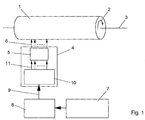
- FIG. 1 shows an embodiment of a drum imagesetter
- Prior art multi-beam exposure device with a recording drum 1, which is rotatable in the circumferential direction 2 about a longitudinal axis 3 is stored.
- An exposure unit 4 moves in the direction of the longitudinal axis 3 along the recording drum 1, which contains an optical head 5, in the N parallel laser beams 6 are generated and modulated.
- the feed rate is set so that the exposure unit 4 after one revolution of the recording drum 1 moved by the total width of the N laser tracks recorded in parallel Has.
- the printing form data of the printing form to be recorded are stored in a computer 7 in a known manner from scanned images, graphic elements and input Texts created and compiled into a printing form.
- the so prepared Printing form data are provided in the printing form memory 8. With the exposure the printing form data from the printing form memory 8 becomes line by line read out and transmitted via a data line 9 to a distributor 10, which in the embodiment is included in the exposure unit 4.
- the distributor 10 distributes the recording lines arriving via the data line 9 cyclically to the N write channels 11, with which the lines pass in parallel to the optical head 5 become.
- the from the printing form memory 8 on the Data line 9 incoming recording lines are from a demultiplexer 12, which is shown schematically as a rotary switch, cyclically into the buffer memory 13 written.
- the buffer memories 13 With the buffer memories 13, the time sequences in Printing form memory 8 on the one hand and in the exposure unit 4 on the other hand decoupled.
- the buffer memories 13 then each become ten recording lines in parallel via the write channels 11 to the input stages 14 of the optical head 5 to hand over.
- Fig. 3 shows such a case on one Example.
- the No. 3 laser beam has failed is what is shown in FIG. 3 by a thick cross in the corresponding input stage 14 is marked.
- the largest contiguous group of remaining Laser beams 6 are then laser beams No. 4 to No. 10. With this group can still be exposed if the demultiplexer 12 is reconfigured that it only cyclically arrives the incoming recording lines into the laser beams No. 4 to No. 10 belonging buffer memory 13 writes.
- the first three Distribution positions of the demultiplexer 12 have to be skipped, which is marked in Fig. 3 by crosses in the respective positions, i.e. the demultiplexer 12 must operate as if it had only seven distribution positions.
- the laser beams No. 1 and No. 2 must be switched off, what in Fig. 3 by a dashed cross in the corresponding input stages 14 is marked.
- the feed speed must be like this can be set that the exposure unit 4 after one revolution of the Recording drum 1 only by the total width of the remaining seven moved laser tracks recorded in parallel.
- the demultiplexer 12 reconfigure one or more failed laser beams 6 to be able to ensure that the recording lines always optimally match each remaining largest remaining group of laser beams 6 will be distributed, one complex control of the distributor 10 required.
- the Exposure unit 4 may also require complex control to switch the exposure system to fewer laser beams.
- the subunit is, for example, the generation of the high-frequency modulation frequencies to control one or more acousto-optical modulators.
- the buffer stores 13, which belong to the laser beams 6 no longer involved in the recording, filled with "empty" recording lines (empty lines), i.e. with data values, which modulate the corresponding laser beams 6 so that these laser beams 6 stay dark. This is done when sending the recording lines over the data line 9 from the computer 7 the empty lines at the required points in the sequence of the recording lines sent.
- the resolution of the blank lines is adapted to the resolution of the printing form data, i.e. the number of pixels in the Blank lines and in the lines of the printing form data are the same.
- Fig. 4 illustrates the method for the previously explained example that the laser beam No. 3 has failed and the exposure system only with the subgroup the laser beams No. 4 to No. 10 are working.
- the computer 7 sends on the Data line 9 first three consecutive blank lines, then the one from the Printing form memory 8 read lines 1 to 7, then three blank lines again, then the lines 8 to 14 read from the printing form memory 8, etc.
- the demultiplexer 12 distributes the lines sent on the data line 9 in its normal Work cyclically on the buffer storage tanks No. 1 to No. 10 the inserted empty lines are always written in the buffer memory No. 1 to No. 3, and the lines 1 to 7, 8 to 14, etc. read from the printing form memory 8 are always written in the buffer memory No. 4 to No. 10.
- the feed speed is set so that the exposure unit 4 after one revolution of the recording drum 1 only by the total width of the the remaining seven laser tracks, which lines 1 to 7, 8 to 14, etc. record from the printing form memory 8.
- the Computer 7 already contains the blank lines during the preparation of the printing form data at the required positions in the printing form memory 8. In that case the lines during the recording in the same order over the data line 9 sent to the exposure unit 4, as found in the printing form memory 8 become.
- the optical head 5 switched off the laser beams 6, which should not be active. The blank lines then need not contain any data values with which the inactive laser beams 6 can be controlled dark, but can print any data contain.
- the multi-beam exposure method according to the invention is suitable for all applications the printing form record, i.e. for all types of printing forms and Recording materials as well as for all mechanical and optical variations of multi-beam exposure arrangements, in particular for drum imagesetters, inner drum imagesetters and flatbed imagesetters.
Landscapes
- Engineering & Computer Science (AREA)
- Multimedia (AREA)
- Signal Processing (AREA)
- Physics & Mathematics (AREA)
- Optics & Photonics (AREA)
- General Engineering & Computer Science (AREA)
- General Physics & Mathematics (AREA)
- Theoretical Computer Science (AREA)
- Exposure And Positioning Against Photoresist Photosensitive Materials (AREA)
- Electronic Switches (AREA)
- Fax Reproducing Arrangements (AREA)
Abstract
Description
- Fig. 1
- ein Ausführungsbeispiel für eine Mehrstrahl-Belichtungsvorrichtung in einem Trommelbelichter (Stand der Technik),
- Fig. 2
- die Funktionsweise des Verteilers im Normalbetrieb (Stand der Technik),
- Fig. 3
- die Funktionsweise des Verteilers bei Ausfall eines Laserstrahls (Stand der Technik), und
- Fig. 4
- die Reihenfolge der Aufzeichnungszeilen nach der Erfindung im Druckformspeicher, auf der Datenleitung und im Pufferspeicher.
Claims (4)
- Verfahren zur Mehrstrahl-Belichtung einer Druckform, vorzugsweise mit Laserstrahlen (6), wobei ein Rechner (7) Druckformdaten als eine Folge von Aufzeichnungszeilen über eine Datenleitung (9) an einen Verteiler (10) überträgt und der Verteiler die Aufzeichnungszeilen zyklisch auf die Eingangsstufen (14) eines Optikkopfes (5) verteilt, in dem N parallele Laserstrahlen (6) erzeugt und mit den Druckformdaten der Aufzeichnungszeilen moduliert werden, dadurch gekennzeichnet, daßdie Laserstrahlen (6) in aktive und nicht aktive Laserstrahlen unterteilt werden,für die aktiven Laserstrahlen Aufzeichnungszeilen der Druckform über die Datenleitung (9) übertragen werden, undfür die nicht aktiven Laserstrahlen Leerzeilen in die übertragene Folge der Aufzeichnungszeilen eingefügt werden.
- Verfahren nach Anspruch 1, dadurch gekennzeichnet, daß die Leerzeilen Datenwerte enthalten, mit denen die nicht aktiven Laserstrahlen dunkel gesteuert werden.
- Verfahren nach Anspruch 1, dadurch gekennzeichnet, daß die Leerzeilen beliebige Datenwerte enthalten und die nicht aktiven Laserstrahlen abgeschaltet werden.
- Verfahren nach mindesten einem der Ansprüche 1 bis 3, dadurch gekennzeichnet, daß die aktiven Laserstrahlen eine zusammenhängende Untergruppe der Laserstrahlen (6) bilden.
Applications Claiming Priority (2)
| Application Number | Priority Date | Filing Date | Title |
|---|---|---|---|
| DE10045168 | 2000-09-13 | ||
| DE10045168A DE10045168B4 (de) | 2000-09-13 | 2000-09-13 | Mehrstrahl-Belichtungsverfahren |
Publications (3)
| Publication Number | Publication Date |
|---|---|
| EP1189425A2 true EP1189425A2 (de) | 2002-03-20 |
| EP1189425A3 EP1189425A3 (de) | 2003-12-03 |
| EP1189425B1 EP1189425B1 (de) | 2008-04-09 |
Family
ID=7655982
Family Applications (1)
| Application Number | Title | Priority Date | Filing Date |
|---|---|---|---|
| EP01117065A Expired - Lifetime EP1189425B1 (de) | 2000-09-13 | 2001-07-13 | Mehrstrahl-Belichtungsverfahren |
Country Status (3)
| Country | Link |
|---|---|
| US (1) | US6570603B2 (de) |
| EP (1) | EP1189425B1 (de) |
| DE (2) | DE10045168B4 (de) |
Cited By (1)
| Publication number | Priority date | Publication date | Assignee | Title |
|---|---|---|---|---|
| WO2007107030A1 (de) * | 2006-03-21 | 2007-09-27 | Xpose Holding Ag | Innentrommelbelichter |
Families Citing this family (4)
| Publication number | Priority date | Publication date | Assignee | Title |
|---|---|---|---|---|
| DE10242142A1 (de) * | 2002-09-03 | 2004-03-25 | Kleo Halbleitertechnik Gmbh & Co Kg | Verfahren und Vorrichtung zum Herstellen von belichteten Strukturen |
| US20050150778A1 (en) * | 2002-11-18 | 2005-07-14 | Lewis Nathan S. | Use of basic polymers in carbon black composite vapor detectors to obtain enhanced sensitivity and classification performance for volatile fatty acids |
| DE102006008080A1 (de) | 2006-02-22 | 2007-08-30 | Kleo Maschinenbau Ag | Belichtungsanlage |
| US9545785B2 (en) | 2008-09-12 | 2017-01-17 | J P Imaging Limited | Method of printing using a reimageable printing plate with an aluminum oxide surface |
Family Cites Families (10)
| Publication number | Priority date | Publication date | Assignee | Title |
|---|---|---|---|---|
| US4732483A (en) * | 1987-03-19 | 1988-03-22 | Zygo Corporation | Interferometric surface profiler |
| US5124720A (en) * | 1990-08-01 | 1992-06-23 | Hewlett-Packard Company | Fault-tolerant dot-matrix printing |
| JP3005136B2 (ja) * | 1992-04-27 | 2000-01-31 | キヤノン株式会社 | プリント装置およびプリント方法 |
| JP3052587B2 (ja) * | 1992-07-28 | 2000-06-12 | 日本電気株式会社 | 露光装置 |
| US5724086A (en) * | 1995-05-12 | 1998-03-03 | Eastman Kodak Company | Printhead having data channels with revisable addresses for interleaving scan lines |
| DE19617552A1 (de) * | 1996-05-02 | 1997-11-06 | Heidelberger Druckmasch Ag | Verfahren und Vorrichtung zur Regelung der Temperatur in einer mit Laserlicht arbeitenden Druckplatten-Beschriftungseinheit, insbesondere einer Offset-Druckmaschine |
| US5923423A (en) * | 1996-09-12 | 1999-07-13 | Sentec Corporation | Heterodyne scatterometer for detecting and analyzing wafer surface defects |
| DE69830894T2 (de) * | 1997-03-26 | 2006-04-06 | Toray Industries, Inc. | Bilderzeugungsvorrichtung,-verfahren und druckvorrichtung |
| JPH1148528A (ja) * | 1997-08-04 | 1999-02-23 | Ricoh Co Ltd | マルチビーム画像形成装置 |
| JP2905764B2 (ja) * | 1997-11-20 | 1999-06-14 | 株式会社金田機械製作所 | 画像変成を利用した印刷用刷版露光装置 |
-
2000
- 2000-09-13 DE DE10045168A patent/DE10045168B4/de not_active Expired - Fee Related
-
2001
- 2001-07-13 DE DE50113827T patent/DE50113827D1/de not_active Expired - Lifetime
- 2001-07-13 EP EP01117065A patent/EP1189425B1/de not_active Expired - Lifetime
- 2001-08-20 US US09/933,506 patent/US6570603B2/en not_active Expired - Lifetime
Cited By (2)
| Publication number | Priority date | Publication date | Assignee | Title |
|---|---|---|---|---|
| WO2007107030A1 (de) * | 2006-03-21 | 2007-09-27 | Xpose Holding Ag | Innentrommelbelichter |
| RU2400939C2 (ru) * | 2006-03-21 | 2010-09-27 | Экспоуз Холдинг Аг | Экспонирующая установка с внутренним барабаном |
Also Published As
| Publication number | Publication date |
|---|---|
| EP1189425B1 (de) | 2008-04-09 |
| US6570603B2 (en) | 2003-05-27 |
| DE10045168B4 (de) | 2008-07-31 |
| DE10045168A1 (de) | 2002-03-21 |
| US20020030733A1 (en) | 2002-03-14 |
| EP1189425A3 (de) | 2003-12-03 |
| DE50113827D1 (de) | 2008-05-21 |
Similar Documents
| Publication | Publication Date | Title |
|---|---|---|
| DE10085017B4 (de) | Datenpfad für Hochleistungs-Mustergenerator | |
| DE2321689C3 (de) | Farbscanner | |
| DE69421241T2 (de) | Schemata mit kombinierten Modulatoren für räumliche Lichtmodulatoren | |
| DE3140081C2 (de) | Elektrophotographischer Mehrfarbendrucker | |
| DE69424604T2 (de) | Räumliche Lichtmodulation | |
| EP1168813B1 (de) | Kompakte Mehrstrahllaserlichtquelle und Interleafrasterscanlinien-Verfahren zur Belichtung von Druckplatten | |
| DE69421957T2 (de) | Verfahren und Vorrichtung zum Ausgleich von Positionsoffsetfehlern von Druckkopfelementen beim elektronisch gesteuerten Rasterdruck | |
| DE4121509A1 (de) | Belichtungs- und lichtmodulationssystem | |
| DE3153624C2 (de) | ||
| DE3212194C2 (de) | ||
| EP1212198B1 (de) | Vorrichtung und verfahren zur kompensation von inhomogenitäten bei abbildungssystemen | |
| DE2454310A1 (de) | Verfahren zum reproduzieren eines originalbildes durch aufzeichnen von punktmatrizen | |
| EP0074422A1 (de) | Verfahren zur Herstellung von Druckformen mittels unregelmässig verteilter Druckpunkte | |
| DE2559628C3 (de) | Infonnationsaufzeichnungsvorrichtung | |
| DE2034679A1 (de) | Aufzeichnungsverfahren und Vor richtung, bei denen Licht verwandt wird, um ein die Aufzeichnung bildendes Material auf ein Aufzeichnungsmedium zu bringen | |
| DE4313111C2 (de) | Verfahren zur Herstellung einer druckenden Vorlage, insbesondere einer Druckform einer Druckmaschine | |
| EP0824070A1 (de) | Verfahren und Vorrichtung zur Herstellung von Druckerzeugnissen | |
| EP0011722A2 (de) | Verfahren und Vorrichtung zum digitalen Steuern der Bildung farbiger Wiedergaben | |
| DE19953144A1 (de) | Verfahren zum Verlängern der Belichtungszeit in Laserscannern | |
| WO1981000466A1 (fr) | Procede d'analyse autotypique de valeurs de tonalite | |
| DE10045168B4 (de) | Mehrstrahl-Belichtungsverfahren | |
| EP1530151B1 (de) | Verfahren zur Korrektur der Schrägaufzeichnung bei der Belichtung von Druckvorlagen | |
| EP1580980B1 (de) | Verfahren und Druckplatte zum Abgleichen der Belichtungsköpfe in einem Belichter für Druckvorlagen | |
| DE69225444T2 (de) | Elektronische Schaltung zur Lieferung ausgewählter Bildsignale an einen Thermodrucker | |
| DE69023383T2 (de) | Randemittierende EL-Drucker und dessen Druckverfahren. |
Legal Events
| Date | Code | Title | Description |
|---|---|---|---|
| PUAI | Public reference made under article 153(3) epc to a published international application that has entered the european phase |
Free format text: ORIGINAL CODE: 0009012 |
|
| AK | Designated contracting states |
Kind code of ref document: A2 Designated state(s): AT BE CH CY DE DK ES FI FR GB GR IE IT LI LU MC NL PT SE TR |
|
| AX | Request for extension of the european patent |
Free format text: AL;LT;LV;MK;RO;SI |
|
| RAP1 | Party data changed (applicant data changed or rights of an application transferred) |
Owner name: HELL GRAVURE SYSTEMS GMBH |
|
| PUAL | Search report despatched |
Free format text: ORIGINAL CODE: 0009013 |
|
| AK | Designated contracting states |
Kind code of ref document: A3 Designated state(s): AT BE CH CY DE DK ES FI FR GB GR IE IT LI LU MC NL PT SE TR |
|
| AX | Request for extension of the european patent |
Extension state: AL LT LV MK RO SI |
|
| 17P | Request for examination filed |
Effective date: 20040223 |
|
| AKX | Designation fees paid |
Designated state(s): CH DE FR GB IT LI |
|
| 17Q | First examination report despatched |
Effective date: 20050317 |
|
| 17Q | First examination report despatched |
Effective date: 20050317 |
|
| RAP1 | Party data changed (applicant data changed or rights of an application transferred) |
Owner name: HELL GRAVURE SYSTEMS GMBH & CO. KG |
|
| GRAP | Despatch of communication of intention to grant a patent |
Free format text: ORIGINAL CODE: EPIDOSNIGR1 |
|
| GRAS | Grant fee paid |
Free format text: ORIGINAL CODE: EPIDOSNIGR3 |
|
| GRAA | (expected) grant |
Free format text: ORIGINAL CODE: 0009210 |
|
| AK | Designated contracting states |
Kind code of ref document: B1 Designated state(s): CH DE FR GB IT LI |
|
| REG | Reference to a national code |
Ref country code: GB Ref legal event code: FG4D Free format text: NOT ENGLISH |
|
| REG | Reference to a national code |
Ref country code: CH Ref legal event code: EP |
|
| REF | Corresponds to: |
Ref document number: 50113827 Country of ref document: DE Date of ref document: 20080521 Kind code of ref document: P |
|
| EN | Fr: translation not filed | ||
| PLBE | No opposition filed within time limit |
Free format text: ORIGINAL CODE: 0009261 |
|
| STAA | Information on the status of an ep patent application or granted ep patent |
Free format text: STATUS: NO OPPOSITION FILED WITHIN TIME LIMIT |
|
| 26N | No opposition filed |
Effective date: 20090112 |
|
| GBPC | Gb: european patent ceased through non-payment of renewal fee |
Effective date: 20080713 |
|
| PG25 | Lapsed in a contracting state [announced via postgrant information from national office to epo] |
Ref country code: FR Free format text: LAPSE BECAUSE OF FAILURE TO SUBMIT A TRANSLATION OF THE DESCRIPTION OR TO PAY THE FEE WITHIN THE PRESCRIBED TIME-LIMIT Effective date: 20090130 |
|
| PG25 | Lapsed in a contracting state [announced via postgrant information from national office to epo] |
Ref country code: GB Free format text: LAPSE BECAUSE OF NON-PAYMENT OF DUE FEES Effective date: 20080713 |
|
| PGFP | Annual fee paid to national office [announced via postgrant information from national office to epo] |
Ref country code: DE Payment date: 20200731 Year of fee payment: 20 |
|
| PGFP | Annual fee paid to national office [announced via postgrant information from national office to epo] |
Ref country code: CH Payment date: 20200725 Year of fee payment: 20 Ref country code: IT Payment date: 20200731 Year of fee payment: 20 |
|
| REG | Reference to a national code |
Ref country code: DE Ref legal event code: R071 Ref document number: 50113827 Country of ref document: DE |