EP1189013A1 - Munitionsartikel mit Antenne für die Satellitennavigation - Google Patents
Munitionsartikel mit Antenne für die Satellitennavigation Download PDFInfo
- Publication number
- EP1189013A1 EP1189013A1 EP01121897A EP01121897A EP1189013A1 EP 1189013 A1 EP1189013 A1 EP 1189013A1 EP 01121897 A EP01121897 A EP 01121897A EP 01121897 A EP01121897 A EP 01121897A EP 1189013 A1 EP1189013 A1 EP 1189013A1
- Authority
- EP
- European Patent Office
- Prior art keywords
- dipole
- antenna
- projectile
- ammunition article
- article according
- Prior art date
- Legal status (The legal status is an assumption and is not a legal conclusion. Google has not performed a legal analysis and makes no representation as to the accuracy of the status listed.)
- Granted
Links
- 239000004020 conductor Substances 0.000 claims abstract description 20
- 239000003989 dielectric material Substances 0.000 claims description 2
- 239000012811 non-conductive material Substances 0.000 claims description 2
- 239000003990 capacitor Substances 0.000 claims 1
- 230000002349 favourable effect Effects 0.000 description 2
- 230000015572 biosynthetic process Effects 0.000 description 1
- 230000001419 dependent effect Effects 0.000 description 1
- 238000011161 development Methods 0.000 description 1
- 230000018109 developmental process Effects 0.000 description 1
- 238000010586 diagram Methods 0.000 description 1
- 238000011156 evaluation Methods 0.000 description 1
- 238000009434 installation Methods 0.000 description 1
- 238000004904 shortening Methods 0.000 description 1
- 230000006641 stabilisation Effects 0.000 description 1
- 238000011105 stabilization Methods 0.000 description 1
Images
Classifications
-
- F—MECHANICAL ENGINEERING; LIGHTING; HEATING; WEAPONS; BLASTING
- F42—AMMUNITION; BLASTING
- F42C—AMMUNITION FUZES; ARMING OR SAFETY MEANS THEREFOR
- F42C19/00—Details of fuzes
-
- F—MECHANICAL ENGINEERING; LIGHTING; HEATING; WEAPONS; BLASTING
- F42—AMMUNITION; BLASTING
- F42B—EXPLOSIVE CHARGES, e.g. FOR BLASTING, FIREWORKS, AMMUNITION
- F42B30/00—Projectiles or missiles, not otherwise provided for, characterised by the ammunition class or type, e.g. by the launching apparatus or weapon used
- F42B30/006—Mounting of sensors, antennas or target trackers on projectiles
-
- H—ELECTRICITY
- H01—ELECTRIC ELEMENTS
- H01Q—ANTENNAS, i.e. RADIO AERIALS
- H01Q1/00—Details of, or arrangements associated with, antennas
- H01Q1/27—Adaptation for use in or on movable bodies
- H01Q1/28—Adaptation for use in or on aircraft, missiles, satellites, or balloons
-
- H—ELECTRICITY
- H01—ELECTRIC ELEMENTS
- H01Q—ANTENNAS, i.e. RADIO AERIALS
- H01Q1/00—Details of, or arrangements associated with, antennas
- H01Q1/27—Adaptation for use in or on movable bodies
- H01Q1/28—Adaptation for use in or on aircraft, missiles, satellites, or balloons
- H01Q1/281—Nose antennas
-
- H—ELECTRICITY
- H01—ELECTRIC ELEMENTS
- H01Q—ANTENNAS, i.e. RADIO AERIALS
- H01Q21/00—Antenna arrays or systems
- H01Q21/24—Combinations of antenna units polarised in different directions for transmitting or receiving circularly and elliptically polarised waves or waves linearly polarised in any direction
-
- H—ELECTRICITY
- H01—ELECTRIC ELEMENTS
- H01Q—ANTENNAS, i.e. RADIO AERIALS
- H01Q9/00—Electrically-short antennas having dimensions not more than twice the operating wavelength and consisting of conductive active radiating elements
- H01Q9/04—Resonant antennas
- H01Q9/16—Resonant antennas with feed intermediate between the extremities of the antenna, e.g. centre-fed dipole
Definitions
- the invention relates to an ammunition article according to the preamble of the claim 1.
- Such an ammunition article is from WO 99/02936 A2 as a drop bomb with in Center of their tail, sandwich or patch-like satellite antenna known.
- their spherical antenna characteristics hold Contact with navigation satellites above the horizon, order through final phase control, namely by means of a comparison between the coordinates given target point and the geodetic actual position of the Ammunition item to increase hit accuracy.
- Such an antenna configuration is for ammunition articles in the form of approximately Artillery shells, however, are inappropriate. Because that from the rear antenna about symmetrical to the longitudinal axis of the projectile towards the rear oriented antenna directional pattern would be during most of the stretched ballistic Flight to the horizon, initially even below, and after the apogee only slightly over it. This makes the probability several Navigation satellites at the same time for a quick and precise determination of the path point to be able to receive sufficiently interference-free for path correction, rather low.
- the present invention is therefore the based on technical problem, one in the manner of an artillery projectile Ammunition articles were placed along a substantially horizontal trajectory to be equipped with an antenna which has a favorable directional characteristic for receiving satellite navigation information.
- the Dipole is equipped with roof capacities that reflect the effective length of the dipole extend by absorbing the current.
- the roof capacities consist of electrically conductive material, such as metallic surfaces or Wires. These conductor pieces are rotationally symmetrical about the longitudinal dipole axis arranged, which ensures the omnidirectional directional characteristic, and connected to the opposite dipole ends.
- the conventional one Dipole emitter has a half-value width of the directional diagram of 78 °.
- the dipole is in a dielectric with high Dielectric constant let in, which also reduces the Dipoles on the space available in the projectile and a Frequency range corresponding to the GPS frequencies is guaranteed.
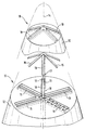
- the ammunition item sketched in the drawing is the Tip 10 of an exchangeable detonator tip 11 of an artillery projectile under a ballistic hood 12.
- Mechanical assembly devices are not shown in detail, Impact sensor and ignition transmitter with safety devices.
- the front in the top10 is a freestanding, as an antenna for receiving Satellite navigation information for the course control of the projectile acting Dipole 13 attached so that the dipole axis concentric with the projectile longitudinal axis 14 coincides and thus an omnidirectional directional characteristic ensures.
- the dipole 13 is preferably on the frequency range of GPS frequencies Voted. To the one specified based on the desired frequencies To reduce the size of the dipole 13, the dipole 13 with roof capacities made of electrically conductive material. Their current consumption causes a virtual extension of the actual dipole.
- the roof capacities can For example, be formed from metallic surfaces or wires, at least connected to the dipole 13 at one end at an angle to the dipole axis are.
- the angle between the conductor pieces 15 and Dipole axis at the lower and upper end of the dipole 13 both the same as be different, as shown in the drawing.
- the angle at the upper end of the dipole 13 is preferably chosen so that the dipole 13 with the conductor pieces 15 can be fitted into the detonator tip 11.
- the single ones Conductor pieces 15 are attached to the dipole 13 so that they are rotationally symmetrical are arranged around the projectile longitudinal axis 14.
- the conductor pieces 15 can meandering 16 and thus the electrical path length of the short Ladder sections should be extended.
- This preferred embodiment is in the drawing representative of all conductor sections 15, for example on a conductor section 16 shown.
- the dipole 13 is equipped with two contact points 17, each of which a signal line 18 leads to the signal processing electronics (not shown).
- the Characteristics of the dipole arrangement influenced and according to the requirements can be set.
- the ballistic hood 12 consists of electrically non-conductive material, for example Plastic.
- the ballistic hood has 12 recesses on its inside 19 on the ends and dimensions of the dipole 13th or correspond to the conductor pieces 15 attached to the dipole 13. In these recesses 19 become the dipole 13 or the conductor pieces 15 at least partially form-fitting.
- the dipole 13 is in dielectric material edged and so, despite the smaller geometry, the one corresponding to the GPS frequencies Frequency range guaranteed.
- an ammunition article, the detonator tip 11 of the projectile, equipped with a dipole satellite antenna pointing in the direction of flight their completely uniform characteristics ensure interference-free reception of satellite navigation information is also possible if, according to Art of an artillery projectile under swirl along an elongated ballistic trajectory is spent.
Landscapes
- Engineering & Computer Science (AREA)
- Physics & Mathematics (AREA)
- Astronomy & Astrophysics (AREA)
- Aviation & Aerospace Engineering (AREA)
- General Physics & Mathematics (AREA)
- Remote Sensing (AREA)
- General Engineering & Computer Science (AREA)
- Details Of Aerials (AREA)
- Variable-Direction Aerials And Aerial Arrays (AREA)
Abstract
Description
Claims (8)
- Munitionsartikel mit Satelliten-Antenne,
dadurch gekennzeichnet, daß in der Zünderspitze (11) eines Projektils eine freistehende Dipol-Antenne (13) unter einer ballistischen Haube (12) derart angeordnet ist, daß die Dipolachse konzentrisch mit der Projektillängsachse (14) zusammenfällt. - Munitionsartikel nach Anspruch 1,
dadurch gekennzeichnet, daß der Dipol (13) auf den Frequenzbereich von GPS-Frequenzen abgestimmt ist. - Munitionsartikel nach einem der vorhergehenden Ansprüche,
dadurch gekennzeichnet, daß der Dipol (13) mit Dachkapazitäten aus elektrisch leitendem Material versehen ist, die in Form von Leiterstücken (15) an wenigstens einem Ende unter einem Winkel zur Dipolachse an den Dipol (13) angeschlossen sind. - Munitionsartikel nach Anspruch 3,
dadurch gekennzeichnet, daß die Leiterstücke (15) rotationssymmetrisch um die Projektillängsachse (14) angeordnet sind. - Munitionsartikel nach Anspruch 4,
dadurch gekennzeichnet, daß Leiterstücke (15) meanderförmig (16) ausgebildet sind. - Munitionsartikel nach einem der vorhergehenden Ansprüche,
dadurch gekennzeichnet, daß die ballistische Haube (12) an ihrer Innenseite Ausnehmungen (19) aufweist, in die der Dipol (13) wenigstens teilweise formschlüssig eingepaßt ist. - Munitionsartikel nach Anspruch 6,
dadurch gekennzeichnet, daß die ballistische Haube (12) aus elektrisch nichtleitendem Material besteht. - Munitionsartikel nach einem der vorhergehenden Ansprüche,
dadurch gekennzeichnet, daß der Dipol (13) in dielektrisches Material eingefaßt ist.
Applications Claiming Priority (2)
| Application Number | Priority Date | Filing Date | Title |
|---|---|---|---|
| DE10045452A DE10045452A1 (de) | 2000-09-14 | 2000-09-14 | Munitionsartikel mit Antenne für die Satellitennavigation |
| DE10045452 | 2000-09-14 |
Publications (2)
| Publication Number | Publication Date |
|---|---|
| EP1189013A1 true EP1189013A1 (de) | 2002-03-20 |
| EP1189013B1 EP1189013B1 (de) | 2006-05-10 |
Family
ID=7656170
Family Applications (1)
| Application Number | Title | Priority Date | Filing Date |
|---|---|---|---|
| EP01121897A Expired - Lifetime EP1189013B1 (de) | 2000-09-14 | 2001-09-12 | Munitionsartikel mit Antenne für die Satellitennavigation |
Country Status (3)
| Country | Link |
|---|---|
| US (1) | US6615734B2 (de) |
| EP (1) | EP1189013B1 (de) |
| DE (2) | DE10045452A1 (de) |
Families Citing this family (11)
| Publication number | Priority date | Publication date | Assignee | Title |
|---|---|---|---|---|
| US7057567B2 (en) * | 2001-10-04 | 2006-06-06 | Diehl Munitionssysteme Gmbh & Co. | Projectile comprising a reception antenna for a satellite navigation receiver |
| DE10303540B4 (de) * | 2003-01-29 | 2014-06-26 | Delphi Technologies, Inc. | Antennenanordnung |
| US7581501B1 (en) | 2006-05-31 | 2009-09-01 | The United States Of America As Represented By The Secretary Of The Navy | Dipole antenna projectile with sensor |
| US7498969B1 (en) * | 2007-02-02 | 2009-03-03 | Rockwell Collins, Inc. | Proximity radar antenna co-located with GPS DRA fuze |
| US7986265B2 (en) | 2008-08-29 | 2011-07-26 | Interstate Electronics Corporation | Systems and methods for determining a rotational position of an object |
| RU2595748C1 (ru) * | 2015-05-28 | 2016-08-27 | Акционерное общество "Конструкторское бюро приборостроения им. академика А.Г. Шипунова" | Управляемый боеприпас |
| US9983315B1 (en) | 2015-05-29 | 2018-05-29 | Interstate Electronics Corporation | Satellite navigation receiver for a rapidly rotating object with improved resistance to jamming |
| US10288395B1 (en) * | 2016-06-09 | 2019-05-14 | The United States Of America As Represented By The Secretary Of The Army | Nosecone inverted F antenna for S-band telemetry |
| US11349201B1 (en) | 2019-01-24 | 2022-05-31 | Northrop Grumman Systems Corporation | Compact antenna system for munition |
| US11581632B1 (en) | 2019-11-01 | 2023-02-14 | Northrop Grumman Systems Corporation | Flexline wrap antenna for projectile |
| SE2400127A1 (sv) * | 2024-11-14 | 2026-05-15 | Bae Systems Bofors Ab | Sensorsystem för tändrör |
Citations (7)
| Publication number | Priority date | Publication date | Assignee | Title |
|---|---|---|---|---|
| US3852756A (en) * | 1974-02-15 | 1974-12-03 | Us Navy | Electrically small resonant antenna with capacitively coupled load |
| US4371875A (en) * | 1974-10-22 | 1983-02-01 | Licentia Patent-Verwaltungs-Gmbh | Projectile antenna |
| GB2176660A (en) * | 1984-05-29 | 1986-12-31 | Licentia Gmbh | Aerial arrangement for electronic proximity fuses or spacing fuses |
| US4700190A (en) * | 1979-10-17 | 1987-10-13 | The United States Of America As Represented By The Secretary Of The Air Force | Missile decoy radar cross section enhancer |
| JPH0936630A (ja) * | 1995-07-20 | 1997-02-07 | Casio Comput Co Ltd | 携帯無線機器用アンテナ |
| WO1999002936A2 (en) | 1997-07-11 | 1999-01-21 | Northrop Grumman Corporation | Gps guided munition |
| EP1143556A1 (de) * | 2000-04-07 | 2001-10-10 | Diehl Munitionssysteme GmbH & Co. KG | Projektil mit Antenne für einen Satelliten-Navigationsempfänger |
Family Cites Families (11)
| Publication number | Priority date | Publication date | Assignee | Title |
|---|---|---|---|---|
| US4387391A (en) * | 1966-08-24 | 1983-06-07 | The United States Of America As Represented By The Secretary Of The Navy | Satellite inspection system using hovering-type interceptors |
| US5507452A (en) * | 1994-08-24 | 1996-04-16 | Loral Corp. | Precision guidance system for aircraft launched bombs |
| US6254031B1 (en) * | 1994-08-24 | 2001-07-03 | Lockhead Martin Corporation | Precision guidance system for aircraft launched bombs |
| US6237496B1 (en) * | 1997-02-26 | 2001-05-29 | Northrop Grumman Corporation | GPS guided munition |
| DE19718947B4 (de) * | 1997-05-05 | 2005-04-28 | Rheinmetall W & M Gmbh | Pilotgeschoß |
| DE19740888C2 (de) * | 1997-09-17 | 1999-09-02 | Rheinmetall W & M Gmbh | Verfahren zum autonomen Lenken eines drallstabilisierten Artilleriegeschosses und autonom gelenktes Artilleriegeschoß zur Durchführung des Verfahrens |
| DE19824288C2 (de) * | 1998-05-29 | 2002-11-14 | Rheinmetall W & M Gmbh | Artilleriegeschoß |
| US6098547A (en) * | 1998-06-01 | 2000-08-08 | Rockwell Collins, Inc. | Artillery fuse circumferential slot antenna for positioning and telemetry |
| US6079333A (en) * | 1998-06-12 | 2000-06-27 | Trimble Navigation Limited | GPS controlled blaster |
| US6345784B1 (en) * | 1999-11-26 | 2002-02-12 | Tadiran Spectralink Ltd | System and method for munition impact assessment |
| US6307514B1 (en) * | 2000-05-01 | 2001-10-23 | Rockwell Collins | Method and system for guiding an artillery shell |
-
2000
- 2000-09-14 DE DE10045452A patent/DE10045452A1/de not_active Withdrawn
-
2001
- 2001-09-12 EP EP01121897A patent/EP1189013B1/de not_active Expired - Lifetime
- 2001-09-12 DE DE50109741T patent/DE50109741D1/de not_active Expired - Fee Related
- 2001-09-13 US US09/951,244 patent/US6615734B2/en not_active Expired - Fee Related
Patent Citations (7)
| Publication number | Priority date | Publication date | Assignee | Title |
|---|---|---|---|---|
| US3852756A (en) * | 1974-02-15 | 1974-12-03 | Us Navy | Electrically small resonant antenna with capacitively coupled load |
| US4371875A (en) * | 1974-10-22 | 1983-02-01 | Licentia Patent-Verwaltungs-Gmbh | Projectile antenna |
| US4700190A (en) * | 1979-10-17 | 1987-10-13 | The United States Of America As Represented By The Secretary Of The Air Force | Missile decoy radar cross section enhancer |
| GB2176660A (en) * | 1984-05-29 | 1986-12-31 | Licentia Gmbh | Aerial arrangement for electronic proximity fuses or spacing fuses |
| JPH0936630A (ja) * | 1995-07-20 | 1997-02-07 | Casio Comput Co Ltd | 携帯無線機器用アンテナ |
| WO1999002936A2 (en) | 1997-07-11 | 1999-01-21 | Northrop Grumman Corporation | Gps guided munition |
| EP1143556A1 (de) * | 2000-04-07 | 2001-10-10 | Diehl Munitionssysteme GmbH & Co. KG | Projektil mit Antenne für einen Satelliten-Navigationsempfänger |
Non-Patent Citations (1)
| Title |
|---|
| PATENT ABSTRACTS OF JAPAN vol. 1997, no. 06 30 June 1997 (1997-06-30) * |
Also Published As
| Publication number | Publication date |
|---|---|
| DE50109741D1 (de) | 2006-06-14 |
| US6615734B2 (en) | 2003-09-09 |
| US20020029716A1 (en) | 2002-03-14 |
| EP1189013B1 (de) | 2006-05-10 |
| DE10045452A1 (de) | 2002-03-28 |
Similar Documents
| Publication | Publication Date | Title |
|---|---|---|
| EP1189013B1 (de) | Munitionsartikel mit Antenne für die Satellitennavigation | |
| EP1282832B1 (de) | Radareinrichtung für den objekt-selbstschutz | |
| DE68907575T2 (de) | Den vollen Raumwinkel abtastende elektronische Antenne mit räumlich zufällig verteilten, verdünnt angeordneten Strahlern. | |
| EP0027643B1 (de) | Einem mit Radar arbeitenden Ziel nachführbare Störsender-Richtantennenanordnung | |
| DE2911885C2 (de) | ||
| EP2449406B1 (de) | Radarsensor für kraftfahrzeuge | |
| DE3424775A1 (de) | Abtaster fuer ein kanonengestartetes projektil | |
| DE10227251A1 (de) | Kombinations-Antenne für Artilleriemunition | |
| EP1178279B1 (de) | Munitionsartikel mit Antenne für die Satellitennavigation | |
| WO2017198326A1 (de) | Antennenanordnung eines lenkflugkörpers mit mehreren radarantennen | |
| EP1143556B1 (de) | Projektil mit Antenne für einen Satelliten-Navigationsempfänger | |
| DE19645496C2 (de) | Um ihre Längsachse rotierende Rakete mit Satelliten-Navigationsempfänger | |
| EP1417731A1 (de) | Schlitzantenne für artilleriemunition | |
| DE102016005910B4 (de) | Antennenanordnung eines Lenkflugkörpers mit einer Radarantenne | |
| DE3543769A1 (de) | Mine zur abwehr von bewegten objekten | |
| DE3722380C2 (de) | ||
| DE957855C (de) | Antennenanordnung fur wenigstens zwei vorzugsweise einander nicht benachbarte Frequenzbander | |
| DE2124710A1 (de) | Sende/Empfangs-Antennensystem mit einer Kompensationseinrichtung | |
| DE19712371A1 (de) | Flächenverteidigungsmine | |
| DE10218169B4 (de) | Antennenelemente für einen Flugkörper | |
| DE3544092A1 (de) | Mehrbereichsantenne fuer den ghz-bereich | |
| EP1391008A1 (de) | Antennenelemente fuer einen flugkorper | |
| DE2317501A1 (de) | Mittelwellenantenne | |
| EP1505407A1 (de) | Multifunktionsradarsystem | |
| EP0669674B1 (de) | Vorrichtung zur Tarnung von Antennen |
Legal Events
| Date | Code | Title | Description |
|---|---|---|---|
| PUAI | Public reference made under article 153(3) epc to a published international application that has entered the european phase |
Free format text: ORIGINAL CODE: 0009012 |
|
| AK | Designated contracting states |
Kind code of ref document: A1 Designated state(s): AT BE CH CY DE DK ES FI FR GB GR IE IT LI LU MC NL PT SE TR Kind code of ref document: A1 Designated state(s): DE FR GB IT |
|
| AX | Request for extension of the european patent |
Free format text: AL;LT;LV;MK;RO;SI |
|
| 17P | Request for examination filed |
Effective date: 20020214 |
|
| AKX | Designation fees paid |
Free format text: DE FR GB IT |
|
| 17Q | First examination report despatched |
Effective date: 20041222 |
|
| RAP1 | Party data changed (applicant data changed or rights of an application transferred) |
Owner name: DIEHL BGT DEFENCE GMBH & CO.KG |
|
| GRAP | Despatch of communication of intention to grant a patent |
Free format text: ORIGINAL CODE: EPIDOSNIGR1 |
|
| GRAS | Grant fee paid |
Free format text: ORIGINAL CODE: EPIDOSNIGR3 |
|
| GRAA | (expected) grant |
Free format text: ORIGINAL CODE: 0009210 |
|
| AK | Designated contracting states |
Kind code of ref document: B1 Designated state(s): DE FR GB IT |
|
| REG | Reference to a national code |
Ref country code: GB Ref legal event code: FG4D Free format text: NOT ENGLISH |
|
| REF | Corresponds to: |
Ref document number: 50109741 Country of ref document: DE Date of ref document: 20060614 Kind code of ref document: P |
|
| GBT | Gb: translation of ep patent filed (gb section 77(6)(a)/1977) |
Effective date: 20060831 |
|
| ET | Fr: translation filed | ||
| PLBE | No opposition filed within time limit |
Free format text: ORIGINAL CODE: 0009261 |
|
| STAA | Information on the status of an ep patent application or granted ep patent |
Free format text: STATUS: NO OPPOSITION FILED WITHIN TIME LIMIT |
|
| 26N | No opposition filed |
Effective date: 20070213 |
|
| PGFP | Annual fee paid to national office [announced via postgrant information from national office to epo] |
Ref country code: FR Payment date: 20080917 Year of fee payment: 8 Ref country code: IT Payment date: 20080925 Year of fee payment: 8 |
|
| PGFP | Annual fee paid to national office [announced via postgrant information from national office to epo] |
Ref country code: GB Payment date: 20080922 Year of fee payment: 8 |
|
| PGFP | Annual fee paid to national office [announced via postgrant information from national office to epo] |
Ref country code: DE Payment date: 20081119 Year of fee payment: 8 |
|
| GBPC | Gb: european patent ceased through non-payment of renewal fee |
Effective date: 20090912 |
|
| REG | Reference to a national code |
Ref country code: FR Ref legal event code: ST Effective date: 20100531 |
|
| PG25 | Lapsed in a contracting state [announced via postgrant information from national office to epo] |
Ref country code: FR Free format text: LAPSE BECAUSE OF NON-PAYMENT OF DUE FEES Effective date: 20090930 Ref country code: DE Free format text: LAPSE BECAUSE OF NON-PAYMENT OF DUE FEES Effective date: 20100401 |
|
| PG25 | Lapsed in a contracting state [announced via postgrant information from national office to epo] |
Ref country code: GB Free format text: LAPSE BECAUSE OF NON-PAYMENT OF DUE FEES Effective date: 20090912 |
|
| PG25 | Lapsed in a contracting state [announced via postgrant information from national office to epo] |
Ref country code: IT Free format text: LAPSE BECAUSE OF NON-PAYMENT OF DUE FEES Effective date: 20090912 |