EP1189008B1 - Heat exchanger - Google Patents
Heat exchanger Download PDFInfo
- Publication number
- EP1189008B1 EP1189008B1 EP00308062A EP00308062A EP1189008B1 EP 1189008 B1 EP1189008 B1 EP 1189008B1 EP 00308062 A EP00308062 A EP 00308062A EP 00308062 A EP00308062 A EP 00308062A EP 1189008 B1 EP1189008 B1 EP 1189008B1
- Authority
- EP
- European Patent Office
- Prior art keywords
- casing
- core
- inlet
- outlet pipes
- fluid
- Prior art date
- Legal status (The legal status is an assumption and is not a legal conclusion. Google has not performed a legal analysis and makes no representation as to the accuracy of the status listed.)
- Expired - Lifetime
Links
Images


Classifications
-
- F—MECHANICAL ENGINEERING; LIGHTING; HEATING; WEAPONS; BLASTING
- F28—HEAT EXCHANGE IN GENERAL
- F28D—HEAT-EXCHANGE APPARATUS, NOT PROVIDED FOR IN ANOTHER SUBCLASS, IN WHICH THE HEAT-EXCHANGE MEDIA DO NOT COME INTO DIRECT CONTACT
- F28D9/00—Heat-exchange apparatus having stationary plate-like or laminated conduit assemblies for both heat-exchange media, the media being in contact with different sides of a conduit wall
- F28D9/0031—Heat-exchange apparatus having stationary plate-like or laminated conduit assemblies for both heat-exchange media, the media being in contact with different sides of a conduit wall the conduits for one heat-exchange medium being formed by paired plates touching each other
- F28D9/0043—Heat-exchange apparatus having stationary plate-like or laminated conduit assemblies for both heat-exchange media, the media being in contact with different sides of a conduit wall the conduits for one heat-exchange medium being formed by paired plates touching each other the plates having openings therein for circulation of at least one heat-exchange medium from one conduit to another
-
- F—MECHANICAL ENGINEERING; LIGHTING; HEATING; WEAPONS; BLASTING
- F28—HEAT EXCHANGE IN GENERAL
- F28F—DETAILS OF HEAT-EXCHANGE AND HEAT-TRANSFER APPARATUS, OF GENERAL APPLICATION
- F28F2250/00—Arrangements for modifying the flow of the heat exchange media, e.g. flow guiding means; Particular flow patterns
- F28F2250/10—Particular pattern of flow of the heat exchange media
- F28F2250/104—Particular pattern of flow of the heat exchange media with parallel flow
-
- F—MECHANICAL ENGINEERING; LIGHTING; HEATING; WEAPONS; BLASTING
- F28—HEAT EXCHANGE IN GENERAL
- F28F—DETAILS OF HEAT-EXCHANGE AND HEAT-TRANSFER APPARATUS, OF GENERAL APPLICATION
- F28F2265/00—Safety or protection arrangements; Arrangements for preventing malfunction
- F28F2265/26—Safety or protection arrangements; Arrangements for preventing malfunction for allowing differential expansion between elements
Definitions
- the present invention relates to a heat exchanger provided with a casing, received in which casing is a heat exchanger core provided with a pair of inlet/outl et convex portions in its opposite end portions, wherein the core has its inlet/outlet convex portions project outward from the casing, and a difference in thermal expansion between the casing and the core is adequately absorbed in the heat exchanger.
- a conventional heat exchanger is provided with a casing, which receives therein a heat exchanger core.
- Apair of inlet/outlet convex portions for example such as inlet/outlet pipes and their corresponding boss portions in which the inlet/outlet pipes are mounted, are provided in opposite longitudinal end portions of the core.
- the inlet/outlet convex portions or pipes pass through the casing through a pair of through-hole portions of the casing, are brought into fluid-tight contact therewith and fixedly mounted therein through a suitable fixing means such as soldering and the like.
- a first fluid is introduced into the core through these inlet/outlet pipes.
- a second fluid is introduced into the casing so that the exchange of heat between the first and the second fluid is conducted in the conventional heat exchanger.
- the conventional heat exchanger having the above construction, for example, cold water which serves as the second fluid is introduced into the casing.
- hot fluid serving as the first fluid is introduced into the core.
- the casing reaches substantially the same temperature as that of the cold water.
- the core reaches substantially the same temperature as that of the hot fluid.
- the core is larger in thermal expansion than the casing, which causes thermal stresses to concentrate in root portions of the inlet/outlet pipes. Consequently, due to such concentration of the thermal stresses, there is a fear that a crack is produced in the root portions of the inlet/outlet pipes in use.
- WO-A-9800679 discloses a heat exchanger according to the preamble of claim 1. Consequently, it would be desirable to be able to provide a heat exchanger, which is provided with means for absorbing any difference in thermal expansion between its components, wherein the means is simple and compact in construction to realize the heat exchanger high in reliability and large in crack-resistance properties.
- a heat exchanger comprising: a core provided with a pair of inlet/outlet pipes, wherein said inlet/outlet pipes are longitudinally spaced apart from each other on an outer peripheral surface of said core; a casing for receiving therein said core, wherein said casing is provided with a pair of through-hole portions which are brought into liquid-tight contact with said inlet/outlet pipes of said core, wherein a first fluid and a second fluid are introduced into said core and said casing, respectively, to perform heat exchange between said first fluid and said second fluid; and a bellows interposed between at least one of said inlet/outlet pipes of said core and a corresponding one of said through-hole portions of said casing to realize fluid-tight contact between said bellows and each of said one of said inlet/outlet pipes of said core and said corresponding one of said through-hole portions of said casing, wherein said bellows permits said one of said inlet/outlet pipes of said core to move relative
- the holding means may be constructed of a flange member and an upper end plate of said core.
- the short sleeve portion of the casing may assume a circular truncated cone shape.
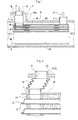
- Fig. 1 shows a heat exchanger .
- Fig. 2 shows deformation in a bellows 6 of the heat exchanger shown in Fig. 1.
- the heat exchanger is provided with a core 3 which is of a multi-plate type, in which: a pair of dish-like metallic plates each provided with a pair of communication holes in its opposite end portions have their peripheral edge portions brought into fluid-tight contact and connected with each other to form an heat exchanger element 12; a plurality of the thus formed elements 12 are stacked together into a pile, and connected with each other through their communication holes.
- a pile thus formed has its top portion covered with an upper end plate 15.
- This upper end plate 15 of the core 3 is provided with a pair of openings in its opposite end portions, in which openings a pair of inlet/outlet pipes 1 are fixedly mounted to project upward as viewed in Fig. 1.
- the above-mentioned pile has its bottom portion covered with a lower end plate having no communication hole, so that the core 3 is formed.
- an outer fin 16 is interposed between adjacent ones of these heat exchanger elements 12.
- Each of the inlet/outlet pipes 1 of the core 3 is constructed as a small-diameter pipe.
- a right-hand one of these inlet/outlet pipes 1 as viewed in Fig. 1 is fixedly mounted in a corresponding one of a pair of through-hole portions 4 of the casing 5 by means of soldering and like fastening means, so that this right-hand one is brought into fluid-tight contact with the corresponding one of the through-hole portions 4 of the casing 5.
- a left-hand one of the inlet/outlet pipes 1 of the core 3 has its upper end portion connected with a lower end portion of the bellows 6 interposed between the left-hand one of the inlet/outlet pipes 1 and a short pipe 10. As shown in Fig.
- this short pipe 10 has its upper end portion brought into fluid-tight contact with a top through-hole portion 4 of a short sleeve portion 7 of the casing 5 and fixedly mounted in this top through-hole portion 4 by means of soldering and like fastening means.
- the short sleeve portion 7 of the casing 5 is provided in an outer peripheral surface of the casing 5 in a position corresponding to that of the left-hand one of the inlet/outlet pipes 1 of the core 3 to project radially outwardly therefrom.
- An inner diameter of the short sleeve portion 7 of the casing 5 is sufficiently larger than an outer diameter of the bellows 6 to permit the bellows 6 to deform laterally.
- a hot oil serving as a first fluid 17 is introduced into the individual heat exchanger elements 12 of the core 3 through a right-hand one of the inlet/outlet pipes 1 of the core 3, as shown in Fig. 1.
- Such a first fluid or hot oil 17 thus passed through the core 3 is then discharged out of the left-hand one of the inlet/outlet pipes 1 of the core 3.
- cold water serving as a second fluid 18 is introduced into the casing 5 from a left-hand inlet opening (not shown), passes through the casing 5, and is then discharged from a right-hand outlet opening (not shown) of the casing 5, wherein heat exchange is performed between the hot oil serving as the first fluid 17 and the cold water serving as the fluid 18.
- a difference in thermal expansion appears between each of the elements 12 of the core 3 and the casing 5.
- Such difference in thermal expansion therebetween is absorbed by deformation of the bellows 6, as shown in Fig. 2.
- deformation of the bellows 6 shown in Fig. 2 is exaggerated for the purpose of illustration.
- An actual amount of such deformation of the bellows 6 is very small in most cases.
- the bellows 6 is capable of absorbing any difference in thermal expansion between the components of the heat exchanger of the present invention to reduce thermal stresses imposed on base portions (i.e., root portions) of the inlet/outlet pipes 1 of the core 3.
- a first embodiment of the heat exchanger of the present invention is shown in Fig. 3. More specifically, in the first embodiment, an inner flange portion 8 of the casing 5 is provided in the root portion of the sleeve-like portion 7 of the casing 5 of the heat exchanger shown in Fig. 1 to form the first embodiment shown in Fig. 3.
- the inner flange portion 8 is sandwiched between: the upper end plate 15 of the core 3; and a flat surface portion (i.e., flange member 9) of a small reservoir portion 11.
- the inner flange portion 8 of the casing 5 is held by holding means 9,15, wherein the holding means 9,15 is constructed of the upper end plate 15 of the core 3 and the flat surface portion (i.e. flange member 9) of the small reservoir portion 11, as is clear from Fig. 3.
- the small reservoir portion 11 is laterally slidable relative to the inner flange portion 8 of the casing 5.
- the sleeve-like portion 7 assumes a circular truncated cone shape. Consequently, in operation, the root portions of the inlet/outlet pipes 1 in the first embodiment of the present invention shown in Fig. 3 are free from any bending moment resulted from a difference in thermal expansion between the components of the heat exchanger.
- the inlet/outlet pipe 1 is also deformed when the bellows 6 is deformed.
- the root portion of the inlet/outlet pipe 1 is subjected to a considerably large amount of bending moment (expressed by the arrow of Fig. 5).
- the holding means 9,15 is capable of effectively minimizing such bending moment.
- Fig. 4 is a second embodiment of the heat exchanger of the present invention, in which the holding means 9,15 is constructed of: the flange member 9 mounted on an outer peripheral portion of the inlet/outlet pipe 1; and the upper end plate 15 of the core 3 to permit the inner flange portion 8 of the casing 5 to laterally slidably move relative to the holding means 9,15.
- the bellows 6 of the heat exchanger of the present invention having the above construction is capable of sufficiently absorbing any difference in thermal expansion between the core 3 and casing 5 even when a difference in length between the core 3 and the casing 5 is produced due to their thermal expansion.
- the heat exchange of the first embodiment of the present invention is provided with the bellows 6 between the top opening portion of the short sleeve portion 7 of the casing 5 and the inlet/outlet pipe 1 of the core 3, it is possible to prevent the bellows 6 from being exposed outward. Further, it is also possible to permit the bellows 6 to be smoothly deformed within the short sleeve portion 7 of the casing 5, which makes it possible to sufficiently absorb any difference in thermal expansion between the core 3 and the casing 5.
- the first embodiment of the heat exchanger of the present invention is provided with the holding means 9,15 in the root portion of the inlet/outlet pipe 1 of the core 3. Since such a holding means 9,15 is slidably movable relative to the inner flange portion 8 of the casing 5, it is possible for the resiliency of such a bellows 6 to minimize any bending moment appearing in the root portion of the inlet/outlet pipe 1 of the core 3, which improves the root portion of the inlet/outlet pipe 1 of the core 3 in reliability.
Description
- The present invention relates to a heat exchanger provided with a casing, received in which casing is a heat exchanger core provided with a pair of inlet/outl et convex portions in its opposite end portions, wherein the core has its inlet/outlet convex portions project outward from the casing, and a difference in thermal expansion between the casing and the core is adequately absorbed in the heat exchanger.
- A conventional heat exchanger is provided with a casing, which receives therein a heat exchanger core. Apair of inlet/outlet convex portions, for example such as inlet/outlet pipes and their corresponding boss portions in which the inlet/outlet pipes are mounted, are provided in opposite longitudinal end portions of the core. The inlet/outlet convex portions or pipes pass through the casing through a pair of through-hole portions of the casing, are brought into fluid-tight contact therewith and fixedly mounted therein through a suitable fixing means such as soldering and the like. A first fluid is introduced into the core through these inlet/outlet pipes. On the other hand, a second fluid is introduced into the casing so that the exchange of heat between the first and the second fluid is conducted in the conventional heat exchanger.
- Now, the problem to be solved by the present invention will be described.
- In the conventional heat exchanger having the above construction, for example, cold water which serves as the second fluid is introduced into the casing. On the other hand, hot fluid serving as the first fluid is introduced into the core. Under such circumstances, the casing reaches substantially the same temperature as that of the cold water. On the other hand, the core reaches substantially the same temperature as that of the hot fluid. In this case, the core is larger in thermal expansion than the casing, which causes thermal stresses to concentrate in root portions of the inlet/outlet pipes. Consequently, due to such concentration of the thermal stresses, there is a fear that a crack is produced in the root portions of the inlet/outlet pipes in use.
- WO-A-9800679 discloses a heat exchanger according to the preamble of claim 1. Consequently, it would be desirable to be able to provide a heat exchanger, which is provided with means for absorbing any difference in thermal expansion between its components, wherein the means is simple and compact in construction to realize the heat exchanger high in reliability and large in crack-resistance properties.
- According to a first aspect of the present invention, there is provided a heat exchanger comprising: a core provided with a pair of inlet/outlet pipes, wherein said inlet/outlet pipes are longitudinally spaced apart from each other on an outer peripheral surface of said core; a casing for receiving therein said core, wherein said casing is provided with a pair of through-hole portions which are brought into liquid-tight contact with said inlet/outlet pipes of said core, wherein a first fluid and a second fluid are introduced into said core and said casing, respectively, to perform heat exchange between said first fluid and said second fluid; and a bellows interposed between at least one of said inlet/outlet pipes of said core and a corresponding one of said through-hole portions of said casing to realize fluid-tight contact between said bellows and each of said one of said inlet/outlet pipes of said core and said corresponding one of said through-hole portions of said casing, wherein said bellows permits said one of said inlet/outlet pipes of said core to move relative to said corresponding one of said through-hole portions of said casing in a radial direction of said corresponding one of said through-hole portions of said casing, a short sleeve portion larger in diameter than said one of said inlet/outlet pipes of said core is provided in a position corresponding to that of said corresponding one of said through-hole portions of said casing; said short sleeve portion of said casing has its top opening portion brought into fluid-tight contact with one of opposite ends of said bellows, the other one of said opposite ends of said bellows being brought into fluid-tight contact with said one of said inlet/outlet pipes of said core, and said short sleeve portion of said casing is provided with an inner flange portion in its root portion; and, a holding means for slidably holding said inner flange portion of said casing is provided in the root portion of said one of said inlet/outlet pipes of said core.
- The holding means may be constructed of a flange member and an upper end plate of said core.
- The short sleeve portion of the casing may assume a circular truncated cone shape.
- The present invention will be more apparent from the following description taken in conjunction with the accompanying drawings in which:
- Fig. 1 is a longitudinal sectional view of a heat exchanger ;
- Fig. 2 is an enlarged longitudinal sectional view of an essential part of the heat exchanger shown in Fig. 1 in use;
- Fig. 3 is a longitudinal section view of a first embodiment of the heat exchanger of the present invention;
- Fig. 4 is a longitudinal sectional view of a second embodiment of the heat exchanger of the present invention, illustrating the holding means (9,15) constructed of the flange (9) member provided in an outer peripheral portion of the inlet/outlet pipe (1) and the upper end plate (15) of the core (3); and
- Fig. 5 is an enlarged longitudinal sectional view of an essential part of each of the embodiments of the present invention shown in Figs. 3 and 4, respectively, illustrating the bending moment (expressed by the arrow) to which the heat exchanger not provided with the holding means (9,15) are subjected.
-
- The best modes for carrying out the present invention will be described in detail using embodiments of the present invention with reference to the accompanying drawings.
- Fig. 1 shows a heat exchanger . Fig. 2 shows deformation in a
bellows 6 of the heat exchanger shown in Fig. 1. - The heat exchanger is provided with a
core 3 which is of a multi-plate type, in which: a pair of dish-like metallic plates each provided with a pair of communication holes in its opposite end portions have their peripheral edge portions brought into fluid-tight contact and connected with each other to form anheat exchanger element 12; a plurality of the thus formedelements 12 are stacked together into a pile, and connected with each other through their communication holes. As shown in Fig. 1, such a pile thus formed has its top portion covered with anupper end plate 15. Thisupper end plate 15 of thecore 3 is provided with a pair of openings in its opposite end portions, in which openings a pair of inlet/outlet pipes 1 are fixedly mounted to project upward as viewed in Fig. 1. Incidentally, the above-mentioned pile has its bottom portion covered with a lower end plate having no communication hole, so that thecore 3 is formed. As is clear from Fig. 1, anouter fin 16 is interposed between adjacent ones of theseheat exchanger elements 12. - Each of the inlet/outlet pipes 1 of the
core 3 is constructed as a small-diameter pipe. A right-hand one of these inlet/outlet pipes 1 as viewed in Fig. 1 is fixedly mounted in a corresponding one of a pair of through-hole portions 4 of thecasing 5 by means of soldering and like fastening means, so that this right-hand one is brought into fluid-tight contact with the corresponding one of the through-hole portions 4 of thecasing 5. On the other hand, a left-hand one of the inlet/outlet pipes 1 of thecore 3 has its upper end portion connected with a lower end portion of thebellows 6 interposed between the left-hand one of the inlet/outlet pipes 1 and ashort pipe 10. As shown in Fig. 1, thisshort pipe 10 has its upper end portion brought into fluid-tight contact with a top through-hole portion 4 of ashort sleeve portion 7 of thecasing 5 and fixedly mounted in this top through-hole portion 4 by means of soldering and like fastening means. - The
short sleeve portion 7 of thecasing 5 is provided in an outer peripheral surface of thecasing 5 in a position corresponding to that of the left-hand one of the inlet/outlet pipes 1 of thecore 3 to project radially outwardly therefrom. An inner diameter of theshort sleeve portion 7 of thecasing 5 is sufficiently larger than an outer diameter of thebellows 6 to permit thebellows 6 to deform laterally. - A hot oil serving as a
first fluid 17 is introduced into the individualheat exchanger elements 12 of thecore 3 through a right-hand one of the inlet/outlet pipes 1 of thecore 3, as shown in Fig. 1. Such a first fluid orhot oil 17 thus passed through thecore 3 is then discharged out of the left-hand one of the inlet/outlet pipes 1 of thecore 3. On the other hand, as viewed from Fig. 1, cold water serving as asecond fluid 18 is introduced into thecasing 5 from a left-hand inlet opening (not shown), passes through thecasing 5, and is then discharged from a right-hand outlet opening (not shown) of thecasing 5, wherein heat exchange is performed between the hot oil serving as thefirst fluid 17 and the cold water serving as thefluid 18. At this time, a difference in thermal expansion appears between each of theelements 12 of thecore 3 and thecasing 5. Such difference in thermal expansion therebetween is absorbed by deformation of thebellows 6, as shown in Fig. 2. Incidentally, such deformation of thebellows 6 shown in Fig. 2 is exaggerated for the purpose of illustration. An actual amount of such deformation of thebellows 6 is very small in most cases. In any case, thebellows 6 is capable of absorbing any difference in thermal expansion between the components of the heat exchanger of the present invention to reduce thermal stresses imposed on base portions (i.e., root portions) of the inlet/outlet pipes 1 of thecore 3. - Next, a first embodiment of the heat exchanger of the present invention is shown in Fig. 3. More specifically, in the first embodiment, an
inner flange portion 8 of thecasing 5 is provided in the root portion of the sleeve-like portion 7 of thecasing 5 of the heat exchanger shown in Fig. 1 to form the first embodiment shown in Fig. 3. In this first embodiment, as is clear from Fig. 3, theinner flange portion 8 is sandwiched between: theupper end plate 15 of thecore 3; and a flat surface portion (i.e., flange member 9) of a small reservoir portion 11. In order words, theinner flange portion 8 of thecasing 5 is held byholding means upper end plate 15 of thecore 3 and the flat surface portion (i.e. flange member 9) of the small reservoir portion 11, as is clear from Fig. 3. In the first embodiment of the present invention having the above construction, the small reservoir portion 11 is laterally slidable relative to theinner flange portion 8 of thecasing 5. Incidentally, in this first embodiment shown in Fig. 3, the sleeve-like portion 7 assumes a circular truncated cone shape. Consequently, in operation, the root portions of the inlet/outlet pipes 1 in the first embodiment of the present invention shown in Fig. 3 are free from any bending moment resulted from a difference in thermal expansion between the components of the heat exchanger. - In other words, in case that the holding means 9,15 is not provided in the heat exchanger of the present invention, as is clear from Fig. 5, the inlet/outlet pipe 1 is also deformed when the
bellows 6 is deformed. As a result of such a deformation of the inlet/outlet pipe 1, the root portion of the inlet/outlet pipe 1 is subjected to a considerably large amount of bending moment (expressed by the arrow of Fig. 5). As is clear from this fact, it is recognized that the holding means 9,15 is capable of effectively minimizing such bending moment. - Fig. 4 is a second embodiment of the heat exchanger of the present invention, in which the holding means 9,15 is constructed of: the
flange member 9 mounted on an outer peripheral portion of the inlet/outlet pipe 1; and theupper end plate 15 of thecore 3 to permit theinner flange portion 8 of thecasing 5 to laterally slidably move relative to theholding means - Now, the action and the effect of the present invention will be described.
- The
bellows 6 of the heat exchanger of the present invention having the above construction is capable of sufficiently absorbing any difference in thermal expansion between thecore 3 andcasing 5 even when a difference in length between thecore 3 and thecasing 5 is produced due to their thermal expansion. - Further, as is clear from Fig. 1, the heat exchange of the first embodiment of the present invention is provided with the
bellows 6 between the top opening portion of theshort sleeve portion 7 of thecasing 5 and the inlet/outlet pipe 1 of thecore 3, it is possible to prevent thebellows 6 from being exposed outward. Further, it is also possible to permit thebellows 6 to be smoothly deformed within theshort sleeve portion 7 of thecasing 5, which makes it possible to sufficiently absorb any difference in thermal expansion between thecore 3 and thecasing 5. - The first embodiment of the heat exchanger of the present invention is provided with the
holding means core 3. Since such a holding means 9,15 is slidably movable relative to theinner flange portion 8 of thecasing 5, it is possible for the resiliency of such abellows 6 to minimize any bending moment appearing in the root portion of the inlet/outlet pipe 1 of thecore 3, which improves the root portion of the inlet/outlet pipe 1 of thecore 3 in reliability.
Claims (3)
- A heat exchanger comprising:a core (3) provided with a pair of inlet/outlet pipes (1), wherein said inlet/outlet pipes (1) are longitudinally spaced apart from each other on an outer peripheral surface of said core (3);a casing (5) for receiving therein said core (3), wherein said casing (5) is provided with a pair of through-hole portions (4) which are brought into liquid-tight contact with said inlet/outlet pipes (1) of said core (3), wherein a first fluid (17) and a second fluid (18) are introduced into said core (3) and said casing (5), respectively, to perform heat exchange between said first fluid (17) and said second fluid (18); anda bellows (6) interposed between at least one of said inlet/outlet pipes (1) of said core (3) and a corresponding one of said through-hole portions (4) of said casing (5) to realize fluid-tight contact between said bellows and each of said one of said inlet/outlet pipes (1) of said core (3) and said corresponding one of said through-hole portions (4) of said casing (5), wherein said bellows (6) permits said one of said inlet/outlet pipes (1) of said core (3) to move relative to said corresponding one of said through-hole portions (4) of said casing (5) in a radial direction of said corresponding one of said through-hole portions (4) of said casing (5),a short sleeve portion (7) larger in diameter than said one of said inlet/outlet pipes (1) of said core (3) is provided in a position corresponding to that of said corresponding one of said through-hole portions (4) of said casing (5); said short sleeve portion (7) of said casing (5) has its top opening portion brought into fluid-tight contact with one of opposite ends of said bellows (6), the other one of said opposite ends of said bellows (6) being brought into fluid-tight contact with said one of said inlet/outlet pipes (1) of said core (3), characterized in that:said short sleeve portion (7) of said casing (5) is provided with an inner flange portion (8) in its root portion; and, a holding means (9,15) for slidably holding said inner flange portion (8) of said casing (5) is provided in the root portion of said one of said inlet/outlet pipes (1) of said core (3).
- A heat exchanger as claimed in claim 1 in which said holding means (9,15) is constructed of a flange member (9) and an upper end plate (15) of said core (3).
- The heat exchanger as claimed in claim 1 or claim 2, in which said short sleeve portion (7) of said casing (5) assumes a circular truncated cone shape.
Priority Applications (2)
| Application Number | Priority Date | Filing Date | Title |
|---|---|---|---|
| EP00308062A EP1189008B1 (en) | 2000-09-15 | 2000-09-15 | Heat exchanger |
| DE60006813T DE60006813T2 (en) | 2000-09-15 | 2000-09-15 | heat exchangers |
Applications Claiming Priority (1)
| Application Number | Priority Date | Filing Date | Title |
|---|---|---|---|
| EP00308062A EP1189008B1 (en) | 2000-09-15 | 2000-09-15 | Heat exchanger |
Publications (2)
| Publication Number | Publication Date |
|---|---|
| EP1189008A1 EP1189008A1 (en) | 2002-03-20 |
| EP1189008B1 true EP1189008B1 (en) | 2003-11-26 |
Family
ID=8173265
Family Applications (1)
| Application Number | Title | Priority Date | Filing Date |
|---|---|---|---|
| EP00308062A Expired - Lifetime EP1189008B1 (en) | 2000-09-15 | 2000-09-15 | Heat exchanger |
Country Status (2)
| Country | Link |
|---|---|
| EP (1) | EP1189008B1 (en) |
| DE (1) | DE60006813T2 (en) |
Cited By (1)
| Publication number | Priority date | Publication date | Assignee | Title |
|---|---|---|---|---|
| DE102015012505B4 (en) * | 2015-09-24 | 2017-08-03 | Audi Ag | Sealing arrangement for a connection device and connection device for an air conditioner |
Families Citing this family (6)
| Publication number | Priority date | Publication date | Assignee | Title |
|---|---|---|---|---|
| DE10230852A1 (en) * | 2002-07-04 | 2004-01-22 | Behr Gmbh & Co. | Heat exchangers, in particular intercoolers for motor vehicles |
| DE102005050738A1 (en) * | 2005-10-22 | 2007-04-26 | Modine Manufacturing Co., Racine | Plate-type heat exchanger for air cooling has aperture edges in at least first part of connection plate with deformations forming part of inflow and outflow channels |
| EP1930680A1 (en) * | 2006-11-21 | 2008-06-11 | Behr GmbH & Co. KG | Stacked heat exchanger with decoupling device |
| DE202008011555U1 (en) * | 2008-08-28 | 2010-01-07 | Autokühler GmbH & Co. KG | Collecting box for a charge air cooler |
| CN102538520A (en) * | 2012-02-28 | 2012-07-04 | 上海艾克森集团有限公司 | Fully-welded plate-type heat exchanger |
| DE102015115147A1 (en) * | 2015-09-09 | 2017-03-09 | Volkswagen Aktiengesellschaft | Heat exchanger and method for producing such a heat exchanger |
Family Cites Families (7)
| Publication number | Priority date | Publication date | Assignee | Title |
|---|---|---|---|---|
| US3850231A (en) * | 1973-05-24 | 1974-11-26 | Combustion Eng | Lmfbr intermediate heat exchanger |
| DE3341263A1 (en) * | 1983-11-15 | 1985-05-23 | Klöckner-Humboldt-Deutz AG, 5000 Köln | Heat exchanger |
| JPH04340088A (en) * | 1991-02-04 | 1992-11-26 | Kazumi Seisakusho:Kk | Plate fin type heat exchanger |
| FR2705769B1 (en) * | 1993-05-26 | 1995-08-11 | Electricite De France | Heat exchanger for contaminated fluid. |
| JP3041753B2 (en) * | 1994-02-16 | 2000-05-15 | 株式会社日立製作所 | Plate heat exchanger |
| SE506845C2 (en) * | 1996-06-28 | 1998-02-16 | Alfa Laval Ab | Flat heat exchanger with bellows lining for connection pipes |
| JP4450887B2 (en) * | 1999-05-20 | 2010-04-14 | 株式会社ティラド | Heat exchanger |
-
2000
- 2000-09-15 EP EP00308062A patent/EP1189008B1/en not_active Expired - Lifetime
- 2000-09-15 DE DE60006813T patent/DE60006813T2/en not_active Expired - Lifetime
Cited By (1)
| Publication number | Priority date | Publication date | Assignee | Title |
|---|---|---|---|---|
| DE102015012505B4 (en) * | 2015-09-24 | 2017-08-03 | Audi Ag | Sealing arrangement for a connection device and connection device for an air conditioner |
Also Published As
| Publication number | Publication date |
|---|---|
| DE60006813D1 (en) | 2004-01-08 |
| EP1189008A1 (en) | 2002-03-20 |
| DE60006813T2 (en) | 2004-09-23 |
Similar Documents
| Publication | Publication Date | Title |
|---|---|---|
| US6283199B1 (en) | Heat exchanger | |
| EP2257757B2 (en) | A plate heat exchanger | |
| KR101055083B1 (en) | Method and apparatus for minimizing the adverse effects of thermal expansion in a heat exchange reactor | |
| US5722485A (en) | Louvered fin heat exchanger | |
| EP2226602B1 (en) | Heat exchange tube | |
| US6408941B1 (en) | Folded fin plate heat-exchanger | |
| US6988541B2 (en) | Oil-cooler-equipped radiator | |
| GB2281388A (en) | Heat pipe | |
| US5052480A (en) | Pipe for coolant condenser | |
| EP1189008B1 (en) | Heat exchanger | |
| PL208367B1 (en) | Plate heat exchanger | |
| US20070000652A1 (en) | Heat exchanger with dimpled tube surfaces | |
| US20150155465A1 (en) | Thermoelectric device | |
| EP2257758B1 (en) | A plate heat exchanger | |
| JP3594606B2 (en) | Plate heat exchanger | |
| KR20200046195A (en) | Heat exchanger for thermoelectric generation system using automobile exhaust heat | |
| US6340051B1 (en) | Heat exchanger with baffle plates | |
| KR100391894B1 (en) | heat exchanger of condensing boiler | |
| KR102511728B1 (en) | Heat exchanger and method manufacturing same | |
| KR0133036B1 (en) | Heat exchanger and manufacture method therefor | |
| EP0903554A1 (en) | Mixture delivery device | |
| WO2001048433A1 (en) | Plate heat exchanger | |
| KR100425917B1 (en) | Heat exchanger fixing structure for boiler | |
| KR0139994Y1 (en) | Heat exchanger | |
| KR200153587Y1 (en) | Hot water heat exchanger of gas boiler |
Legal Events
| Date | Code | Title | Description |
|---|---|---|---|
| PUAI | Public reference made under article 153(3) epc to a published international application that has entered the european phase |
Free format text: ORIGINAL CODE: 0009012 |
|
| AK | Designated contracting states |
Kind code of ref document: A1 Designated state(s): DE FR GB Kind code of ref document: A1 Designated state(s): AT BE CH CY DE DK ES FI FR GB GR IE IT LI LU MC NL PT SE |
|
| AX | Request for extension of the european patent |
Free format text: AL;LT;LV;MK;RO;SI |
|
| 17P | Request for examination filed |
Effective date: 20020722 |
|
| AKX | Designation fees paid |
Free format text: DE FR GB |
|
| 17Q | First examination report despatched |
Effective date: 20021120 |
|
| GRAH | Despatch of communication of intention to grant a patent |
Free format text: ORIGINAL CODE: EPIDOS IGRA |
|
| GRAS | Grant fee paid |
Free format text: ORIGINAL CODE: EPIDOSNIGR3 |
|
| GRAA | (expected) grant |
Free format text: ORIGINAL CODE: 0009210 |
|
| AK | Designated contracting states |
Kind code of ref document: B1 Designated state(s): DE FR GB |
|
| REG | Reference to a national code |
Ref country code: GB Ref legal event code: FG4D |
|
| REF | Corresponds to: |
Ref document number: 60006813 Country of ref document: DE Date of ref document: 20040108 Kind code of ref document: P |
|
| REG | Reference to a national code |
Ref country code: IE Ref legal event code: FG4D |
|
| ET | Fr: translation filed | ||
| PLBE | No opposition filed within time limit |
Free format text: ORIGINAL CODE: 0009261 |
|
| STAA | Information on the status of an ep patent application or granted ep patent |
Free format text: STATUS: NO OPPOSITION FILED WITHIN TIME LIMIT |
|
| 26N | No opposition filed |
Effective date: 20040827 |
|
| REG | Reference to a national code |
Ref country code: IE Ref legal event code: MM4A |
|
| REG | Reference to a national code |
Ref country code: FR Ref legal event code: CD |
|
| PGFP | Annual fee paid to national office [announced via postgrant information from national office to epo] |
Ref country code: GB Payment date: 20120912 Year of fee payment: 13 |
|
| PGFP | Annual fee paid to national office [announced via postgrant information from national office to epo] |
Ref country code: DE Payment date: 20120912 Year of fee payment: 13 Ref country code: FR Payment date: 20120926 Year of fee payment: 13 |
|
| GBPC | Gb: european patent ceased through non-payment of renewal fee |
Effective date: 20130915 |
|
| REG | Reference to a national code |
Ref country code: DE Ref legal event code: R119 Ref document number: 60006813 Country of ref document: DE Effective date: 20140401 |
|
| REG | Reference to a national code |
Ref country code: FR Ref legal event code: ST Effective date: 20140530 |
|
| PG25 | Lapsed in a contracting state [announced via postgrant information from national office to epo] |
Ref country code: GB Free format text: LAPSE BECAUSE OF NON-PAYMENT OF DUE FEES Effective date: 20130915 |
|
| PG25 | Lapsed in a contracting state [announced via postgrant information from national office to epo] |
Ref country code: DE Free format text: LAPSE BECAUSE OF NON-PAYMENT OF DUE FEES Effective date: 20140401 Ref country code: FR Free format text: LAPSE BECAUSE OF NON-PAYMENT OF DUE FEES Effective date: 20130930 |