EP1187250A2 - Mikrowellenanordnung - Google Patents
Mikrowellenanordnung Download PDFInfo
- Publication number
- EP1187250A2 EP1187250A2 EP01116972A EP01116972A EP1187250A2 EP 1187250 A2 EP1187250 A2 EP 1187250A2 EP 01116972 A EP01116972 A EP 01116972A EP 01116972 A EP01116972 A EP 01116972A EP 1187250 A2 EP1187250 A2 EP 1187250A2
- Authority
- EP
- European Patent Office
- Prior art keywords
- chamber
- microwave
- arrangement according
- coaxial
- cavity
- Prior art date
- Legal status (The legal status is an assumption and is not a legal conclusion. Google has not performed a legal analysis and makes no representation as to the accuracy of the status listed.)
- Granted
Links
Images

Classifications
-
- H—ELECTRICITY
- H01—ELECTRIC ELEMENTS
- H01J—ELECTRIC DISCHARGE TUBES OR DISCHARGE LAMPS
- H01J37/00—Discharge tubes with provision for introducing objects or material to be exposed to the discharge, e.g. for the purpose of examination or processing thereof
- H01J37/32—Gas-filled discharge tubes
- H01J37/32009—Arrangements for generation of plasma specially adapted for examination or treatment of objects, e.g. plasma sources
- H01J37/32192—Microwave generated discharge
-
- H—ELECTRICITY
- H05—ELECTRIC TECHNIQUES NOT OTHERWISE PROVIDED FOR
- H05H—PLASMA TECHNIQUE; PRODUCTION OF ACCELERATED ELECTRICALLY-CHARGED PARTICLES OR OF NEUTRONS; PRODUCTION OR ACCELERATION OF NEUTRAL MOLECULAR OR ATOMIC BEAMS
- H05H1/00—Generating plasma; Handling plasma
- H05H1/24—Generating plasma
- H05H1/46—Generating plasma using applied electromagnetic fields, e.g. high frequency or microwave energy
Definitions
- the invention relates to a microwave arrangement with a Coupling device for a microwave source, an output, a circulator and a load to dampen over the Output returning microwaves.
- Microwaves used to generate plasma are often used by the microwave generator via waveguides to the antennas installed in the treatment chambers directed. Since in such systems a degree with Wave resistance of the waveguide cannot be guaranteed can, it is necessary to remove the returning waves from the Keep microwave transmitters away. These are known to Arrangements provided circulators that the direct the returning microwaves into a water load. Overall, the components of such systems require often a lot of installation space and considerable installation effort.
- the microwave arrangement according to the invention enables one extremely compact system, several depending on requirements Arrangements according to the invention for the supply of several Plasma generation systems or other microwave devices, for example, heating devices can be used.
- the arrangement according to the invention is correspondingly larger perform.
- An advantageous embodiment of the invention exists in that the channels by centric storage of conductors are designed as coaxial lines. So that's already there the output as a coaxial line so that antennas can be connected directly.
- microwaves are thereby possible that the first with the second chamber connecting conductor protrudes into the first chamber and with an antenna running perpendicular to the conductor is.
- An advantageous coupling of the returning Microwaves in the load can be used in the invention Arrangement may be provided that the second with conductor connecting the third chamber to the third chamber protrudes and forms an antenna. It is preferred provided that the shape of the in the third chamber protruding part of the conductor to the impedance conditions is adjusted in the third chamber.
- Attenuation of the returning microwaves is one Development of the invention provided that in the third chamber from a water hose microwave-transparent material laid in a loop is.
- the third chamber is preferably cylindrical.
- Microwave arrangement is advantageous in another Design possible in that the block such is divided into two that at least the second chamber and the Half of the channels fall into a sub-block.
- the microwave arrangement according to the invention different materials suitable. Because of the small Weight and good conductivity is preferred provided that the block is made of aluminum.
- Such a load - also called a calorimetric load - serves high-frequency vibration energy in heat convert.
- the heat is in a circulating liquid absorbed and dissipated.
- the performance can also are determined as the product of the flow rate, the Temperature rise and the specific heat of the Liquid, preferably water.
- the second Arrangement according to the invention has the advantage of an extreme compact and simple structure so that it can also be used as a Single component is easy and inexpensive to manufacture.
- An advantageous embodiment of the invention Arrangement is that the cavity is cylindrical is, with the axis in the same direction as the axis of the coaxial input runs.
- the hose runs in a loop Preferably in the Arrangement according to the invention provided that the hose runs in a loop.
- the second arrangement according to the invention can also be used for measuring the microwave energy when testing microwave systems can be used, for which a coaxial output with a Energy provided from the cavity receiving antenna is.
- the second arrangement according to the invention be designed so that the cavity from one cup-shaped part, the bottom of which is the coaxial Entrance is arranged, and that in a cover of the entrance and the outlet for the absorber liquid and the coaxial Output are arranged.
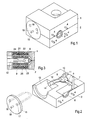
- FIG. 1 to 3 consists of a two-part block 1, 2 with an opening 3 and four Stud 4 for mounting a not shown Magnetron. Instead of the studs 4 are the expert other fasteners are also available. Behind the Opening 3 is the first chamber 6, which for Coupling of the microwaves is used and into an antenna 7 a first coaxial line 8 protrudes.
- the first Coaxial line represents the first port of a circulator 9 which also has a second port that is connected via a Coaxial line 10 is connected to the output 11, and has a third port that is connected to another Coaxial line 12 is connected to a chamber 13 and in Form of an antenna 14 projects into this.
- Chamber 13 serves as a so-called water load and comes with a lid 15 closed with two holes 16, 17 through one only indicated water hose 18 is carried out in the Chamber 13 is laid in a loop. Also in the lid 15 a plug device 19 is provided, via which a part the microwave energy are coupled out for measurement purposes can.
- Fig. 3 shows details in the form of a sectional view of the circulator with the disc 9 and the conductors or ports 8, 12.
- the circulator 21 there are two ferrite disks 22, 23, which Permanent magnets 24, 25 are magnetized.
- the Permanent magnets 24, 25 are outside the block, so that they are not demagnetized by the microwaves.
- the wall thickness of the sub-blocks is in the range of Circulator strong compared to the other areas reduced so that the permanent magnets 24, 25 as possible lie close to the ferrite disks 22, 23.
- Fig. 4 shows a longitudinal section through a Embodiment for a water load according to the invention a housing 31 and a cover 32. Through an opening 33 protrudes an antenna 35 with a roof capacity 36, the electrically and mechanically with a coaxial connector 34 for the supply of microwaves is connected.
- the Cover 32 two openings for connecting the loop laid hose 18 on a water inlet and outlet.
- Fig. 4 only one of the connections is visible, the one from a screw sleeve 37, which at its ends Has hose connections 38, 39.
- hose connection 38 On the outside Hose connection 38 is for the water supply or drainage a hose can be pulled open while the inner hose connection 39 holds the loop-shaped hose 18.
- Tapred Press pieces 40 are provided, which when screwing in Screw sleeve 37 the hose to the hose connector 39 press.
Landscapes
- Physics & Mathematics (AREA)
- Engineering & Computer Science (AREA)
- Plasma & Fusion (AREA)
- Electromagnetism (AREA)
- Spectroscopy & Molecular Physics (AREA)
- Chemical & Material Sciences (AREA)
- Analytical Chemistry (AREA)
- Constitution Of High-Frequency Heating (AREA)
- Non-Reversible Transmitting Devices (AREA)
- Plasma Technology (AREA)
- Radar Systems Or Details Thereof (AREA)
- Variable-Direction Aerials And Aerial Arrays (AREA)
Abstract
Description
- einen Hohlraum mit elektrisch leitenden Wänden,
- einen koaxialen Eingang mit einem Innenleiter, dessen in den Hohlraum ragender Teil eine Antenne bildet,
- einen im Hohlraum befindlichen Schlauch aus mikrowellen-durchlässigem Material zur Führung von Absorberflüssigkeit und
- mindestens einem Eingang und mindestens einem Ausgang für die Absorberflüssigkeit.
- Fig. 1
- eine Ansicht eines ersten Ausführungsbeispiels,
- Fig. 2
- eine Ansicht des ersten Ausführungsbeispiels bei entferntem oberen Teilblock,
- Fig. 3
- eine Detailansicht des Zirkulators und
- Fig. 4
- einen Längsschnitt eines zweiten Ausführungsbeispiels.
Claims (15)
- Mikrowellenanordnung mit einer Koppeleinrichtung für eine Mikrowellenquelle, einem Ausgang, einem Zirkulator und einer Last zur Dämpfung von über den Ausgang zurücklaufenden Mikrowellen, dadurch gekennzeichnet, daß in einem Block (1, 2) aus leitendem Werkstoff eine erste Kammer (6) zur Einkopplung der Mikrowellen, eine zweite Kammer (21) für den Zirkulator (9) und eine dritte Kammer (13) für die Last angeordnet sind und daß die erste mit der zweiten und die zweite mit der dritten Kammer und mit dem Ausgang über je einen Kanal verbunden sind.
- Mikrowellenanordnung nach Anspruch 1, dadurch gekennzeichnet, daß die Kanäle durch zentrische Lagerung von Leitern (8, 10, 12) als Koaxialleitungen ausgebildet sind.
- Mikrowellenanordnung nach Anspruch 2, dadurch gekennzeichnet, daß der die erste mit der zweiten Kammer verbindende Leiter (8) in die erste Kammer (6) hineinragt und mit einer senkrecht zum Leiter (8) verlaufenden Antenne (7) versehen ist.
- Mikrowellenanordnung nach einem der vorhergehenden Ansprüche, dadurch gekennzeichnet, daß der die zweite mit der dritten Kammer verbindende Leiter (12) in die dritte Kammer (13) hineinragt und eine Antenne (14) bildet.
- Mikrowellenanordnung nach Anspruch 4, dadurch gekennzeichnet, daß die Form des in die dritte Kammer hineinragenden Teils (14) des Leiters (12) an die Impedanzverhältnisse in der dritten Kammer angepaßt ist.
- Mikrowellenanordnung nach einem der vorhergehenden Ansprüche, dadurch gekennzeichnet, daß in der dritten Kammer (13) ein Wasserschlauch (18) aus mikrowellen-transparentem Material schleifenförmig verlegt ist.
- Mikrowellenanordnung nach Anspruch 6, dadurch gekennzeichnet, daß die dritte Kammer (13) zylinderförmig ist.
- Mikrowellenanordnung nach einem der vorhergehenden Ansprüche, dadurch gekennzeichnet, daß der Block (1, 2) derart zweigeteilt ist, daß mindestens die zweite Kammer (21) und die Kanäle hälftig in je einen Teilblock (1, 2) fallen.
- Mikrowellenanordnung nach einem der vorhergehenden Ansprüche, dadurch gekennzeichnet, daß der Block (1, 2) auf beiden Seiten neben der zweiten Kammer (21) außen Aussparungen für je einen Permanentmagneten (24, 25) enthält.
- Mikrowellenanordnung nach einem der vorhergehenden Ansprüche, dadurch gekennzeichnet, daß der Block (1, 2) aus Aluminium besteht.
- Anordnung zum Absorbieren von Mikrowellenenergie, gekennzeichnet durcheinen Hohlraum mit elektrisch leitenden Wänden (31, 32),einen koaxialen Eingang (34) mit einem Innenleiter, dessen in den Hohlraum ragender Teil eine Antenne (35, 36) bildet,einen im Hohlraum befindlichen Schlauch (18) aus mikrowellen-durchlässigem Material zur Führung von Absorberflüssigkeit undmindestens einem Eingang und mindestens einem Ausgang (37, 38, 39) für die Absorberflüssigkeit.
- Anordnung nach Anspruch 1, dadurch gekennzeichnet, daß der Hohlraum zylinderförmig ist, wobei die Achse in gleicher Richtung wie die Achse des koaxialen Eingangs (34) verläuft.
- Anordnung nach einem der Ansprüche 11 oder 12, dadurch gekennzeichnet, daß der Schlauch (18) schleifenförmig verläuft.
- Anordnung nach einem der Ansprüche 12 bis 13, dadurch gekennzeichnet, daß ein koaxialer Ausgang (19) mit einer Energie aus dem Hohlraum aufnehmenden Antenne (41) vorgesehen ist.
- Anordnung nach Anspruch 14, dadurch gekennzeichnet, daß der Hohlraum aus einem becherförmigen Teil (31) besteht, an dessen Boden der koaxiale Eingang (34) angeordnet ist, und daß in einem Deckel (32) der Eingang und der Ausgang (37, 38, 39) für die Absorberflüssigkeit und der koaxiale Ausgang (19) angeordnet sind.
Applications Claiming Priority (2)
| Application Number | Priority Date | Filing Date | Title |
|---|---|---|---|
| DE10034028 | 2000-07-13 | ||
| DE10034028A DE10034028C2 (de) | 2000-07-13 | 2000-07-13 | Mikrowellenanordnung |
Publications (3)
| Publication Number | Publication Date |
|---|---|
| EP1187250A2 true EP1187250A2 (de) | 2002-03-13 |
| EP1187250A3 EP1187250A3 (de) | 2002-03-27 |
| EP1187250B1 EP1187250B1 (de) | 2006-01-11 |
Family
ID=7648772
Family Applications (1)
| Application Number | Title | Priority Date | Filing Date |
|---|---|---|---|
| EP01116972A Expired - Lifetime EP1187250B1 (de) | 2000-07-13 | 2001-07-12 | Mikrowellenanordnung |
Country Status (3)
| Country | Link |
|---|---|
| EP (1) | EP1187250B1 (de) |
| AT (1) | ATE315836T1 (de) |
| DE (2) | DE10034028C2 (de) |
Cited By (1)
| Publication number | Priority date | Publication date | Assignee | Title |
|---|---|---|---|---|
| US9263783B2 (en) | 2014-01-21 | 2016-02-16 | Honeywell International Inc. | Waveguide circulator having stepped floor/ceiling and quarter-wave dielectric transformer |
Families Citing this family (1)
| Publication number | Priority date | Publication date | Assignee | Title |
|---|---|---|---|---|
| ATE504101T1 (de) * | 2005-12-12 | 2011-04-15 | Valvo Bauelemente Gmbh | Hohlleiter-einkopplungs- und übertragungsvorrichtung |
Family Cites Families (6)
| Publication number | Priority date | Publication date | Assignee | Title |
|---|---|---|---|---|
| GB761366A (en) * | 1953-09-05 | 1956-11-14 | Emi Ltd | Improvements in or relating to waveguides and transmission lines for high frequency electro-magnetic energy |
| US3085212A (en) * | 1961-04-17 | 1963-04-09 | Sperry Rand Corp | Tunable circulator |
| DE2260863A1 (de) * | 1972-12-13 | 1974-06-27 | Philips Patentverwaltung | Dreitor-zirkulator in triplate-bauweise |
| US4697158A (en) * | 1986-04-15 | 1987-09-29 | Electromagnetic Sciences, Inc. | Reduced height waveguide circulator |
| DE4037091C2 (de) * | 1990-11-22 | 1996-06-20 | Leybold Ag | Vorrichtung für die Erzeugung eines homogenen Mikrowellenfeldes |
| US5724010A (en) * | 1996-09-09 | 1998-03-03 | Hughes Electronics | Wideband "Y" Junction isolator/circulator at v-band |
-
2000
- 2000-07-13 DE DE10034028A patent/DE10034028C2/de not_active Expired - Fee Related
-
2001
- 2001-07-12 EP EP01116972A patent/EP1187250B1/de not_active Expired - Lifetime
- 2001-07-12 AT AT01116972T patent/ATE315836T1/de active
- 2001-07-12 DE DE50108652T patent/DE50108652D1/de not_active Expired - Lifetime
Cited By (1)
| Publication number | Priority date | Publication date | Assignee | Title |
|---|---|---|---|---|
| US9263783B2 (en) | 2014-01-21 | 2016-02-16 | Honeywell International Inc. | Waveguide circulator having stepped floor/ceiling and quarter-wave dielectric transformer |
Also Published As
| Publication number | Publication date |
|---|---|
| ATE315836T1 (de) | 2006-02-15 |
| DE10034028C2 (de) | 2002-05-02 |
| EP1187250B1 (de) | 2006-01-11 |
| DE50108652D1 (de) | 2006-04-06 |
| EP1187250A3 (de) | 2002-03-27 |
| DE10034028A1 (de) | 2002-01-24 |
Similar Documents
| Publication | Publication Date | Title |
|---|---|---|
| DE69326118T2 (de) | Polarisationsseparator und Modenwandler für Hohlleiter-Mikrostreifenleiter in Mikrowellengeräten | |
| DE69400101T2 (de) | Elektrisches Masseverbindungssystem zwischen einer koaxialen Steckverbindung und der Platte einer hyperfrequenten Schaltung und elektrische Verbindungsvorrichtung für dieses System | |
| DE69515003T2 (de) | Selbstsichernde EMI Abschirmung | |
| DE69317390T2 (de) | Mikrowellenanordnung mit mindestens einem Übergang zwischen einer auf einem Substrat integrierten Übertragungsleitung und einem Hohlleiter | |
| DE2202276C3 (de) | Hochfrequenz-Erhitzungsgerät | |
| DE102010063167A1 (de) | Mit Mikrowellen arbeitendes Messgerät | |
| DE2335501A1 (de) | Elektrische verbindungsvorrichtung | |
| EP0957371B1 (de) | Radarsensor | |
| DE69904550T2 (de) | Polarisationsweiche mit doppelter Seitenwandkopplung | |
| DE3876862T2 (de) | Mikrowellenprimaersende- und empfangsduplexer fuer orthogonalpolarisierte wellen. | |
| DE10221856A1 (de) | Einrichtung zur Trennung polarisierter Wellen, HF-Wellen-Empfangsumsetzer und Antennenvorrichtung | |
| DE3619220C2 (de) | ||
| DE3835178C2 (de) | Elektrisches Gerät | |
| DE102016210388A1 (de) | Mikrowellengenerator für ein Mikrowellengerät und Mikrowellengerät | |
| DE102015113945A1 (de) | Radarsensor für ein Kraftfahrzeug, Anordnung und Kraftfahrzeug | |
| EP1187250A2 (de) | Mikrowellenanordnung | |
| DE2307788C3 (de) | Magnetron | |
| DE69421861T2 (de) | Variabler Leistungsteiler mit Drehflügeln | |
| DE602005000472T2 (de) | Testsonde mit integriertem Schaltkreis | |
| DE3687781T2 (de) | Verbinder fuer mikrowellenvorrichtung der bequem mit den mikrowellenkreiskomponenten verbindbar ist. | |
| EP3531155A1 (de) | Nmr-probenkopf mit trageteil (backbone) im abschirmrohr | |
| DE20314618U1 (de) | Strom- und Signaldurchführung zwischen Kammern des Gehäuses eines Feldgerätes | |
| DE3851861T2 (de) | Mikrowellen-Mischer. | |
| DE19734097A1 (de) | Mikrowellen-Bauelement | |
| DE1541490A1 (de) | Mikrowellenzirkulator |
Legal Events
| Date | Code | Title | Description |
|---|---|---|---|
| PUAI | Public reference made under article 153(3) epc to a published international application that has entered the european phase |
Free format text: ORIGINAL CODE: 0009012 |
|
| PUAL | Search report despatched |
Free format text: ORIGINAL CODE: 0009013 |
|
| AK | Designated contracting states |
Kind code of ref document: A2 Designated state(s): AT BE CH CY DE DK ES FI FR GB GR IE IT LI LU MC NL PT SE TR |
|
| AX | Request for extension of the european patent |
Free format text: AL;LT;LV;MK;RO;SI |
|
| AK | Designated contracting states |
Kind code of ref document: A3 Designated state(s): AT BE CH CY DE DK ES FI FR GB GR IE IT LI LU MC NL PT SE TR |
|
| AX | Request for extension of the european patent |
Free format text: AL;LT;LV;MK;RO;SI |
|
| 17P | Request for examination filed |
Effective date: 20020921 |
|
| AKX | Designation fees paid |
Free format text: AT BE CH CY DE DK ES FI FR GB GR IE IT LI LU MC NL PT SE TR |
|
| 17Q | First examination report despatched |
Effective date: 20030625 |
|
| GRAP | Despatch of communication of intention to grant a patent |
Free format text: ORIGINAL CODE: EPIDOSNIGR1 |
|
| GRAS | Grant fee paid |
Free format text: ORIGINAL CODE: EPIDOSNIGR3 |
|
| GRAA | (expected) grant |
Free format text: ORIGINAL CODE: 0009210 |
|
| AK | Designated contracting states |
Kind code of ref document: B1 Designated state(s): AT BE CH CY DE DK ES FI FR GB GR IE IT LI LU MC NL PT SE TR |
|
| PG25 | Lapsed in a contracting state [announced via postgrant information from national office to epo] |
Ref country code: FI Free format text: LAPSE BECAUSE OF FAILURE TO SUBMIT A TRANSLATION OF THE DESCRIPTION OR TO PAY THE FEE WITHIN THE PRESCRIBED TIME-LIMIT Effective date: 20060111 Ref country code: IE Free format text: LAPSE BECAUSE OF FAILURE TO SUBMIT A TRANSLATION OF THE DESCRIPTION OR TO PAY THE FEE WITHIN THE PRESCRIBED TIME-LIMIT Effective date: 20060111 Ref country code: NL Free format text: LAPSE BECAUSE OF FAILURE TO SUBMIT A TRANSLATION OF THE DESCRIPTION OR TO PAY THE FEE WITHIN THE PRESCRIBED TIME-LIMIT Effective date: 20060111 Ref country code: IT Free format text: LAPSE BECAUSE OF FAILURE TO SUBMIT A TRANSLATION OF THE DESCRIPTION OR TO PAY THE FEE WITHIN THE PRESCRIBED TIME-LIMIT;WARNING: LAPSES OF ITALIAN PATENTS WITH EFFECTIVE DATE BEFORE 2007 MAY HAVE OCCURRED AT ANY TIME BEFORE 2007. THE CORRECT EFFECTIVE DATE MAY BE DIFFERENT FROM THE ONE RECORDED. Effective date: 20060111 |
|
| REG | Reference to a national code |
Ref country code: CH Ref legal event code: EP |
|
| REG | Reference to a national code |
Ref country code: IE Ref legal event code: FG4D Free format text: LANGUAGE OF EP DOCUMENT: GERMAN |
|
| REF | Corresponds to: |
Ref document number: 50108652 Country of ref document: DE Date of ref document: 20060406 Kind code of ref document: P |
|
| PG25 | Lapsed in a contracting state [announced via postgrant information from national office to epo] |
Ref country code: DK Free format text: LAPSE BECAUSE OF FAILURE TO SUBMIT A TRANSLATION OF THE DESCRIPTION OR TO PAY THE FEE WITHIN THE PRESCRIBED TIME-LIMIT Effective date: 20060411 Ref country code: SE Free format text: LAPSE BECAUSE OF FAILURE TO SUBMIT A TRANSLATION OF THE DESCRIPTION OR TO PAY THE FEE WITHIN THE PRESCRIBED TIME-LIMIT Effective date: 20060411 |
|
| PG25 | Lapsed in a contracting state [announced via postgrant information from national office to epo] |
Ref country code: ES Free format text: LAPSE BECAUSE OF FAILURE TO SUBMIT A TRANSLATION OF THE DESCRIPTION OR TO PAY THE FEE WITHIN THE PRESCRIBED TIME-LIMIT Effective date: 20060422 |
|
| GBT | Gb: translation of ep patent filed (gb section 77(6)(a)/1977) |
Effective date: 20060516 |
|
| PG25 | Lapsed in a contracting state [announced via postgrant information from national office to epo] |
Ref country code: PT Free format text: LAPSE BECAUSE OF FAILURE TO SUBMIT A TRANSLATION OF THE DESCRIPTION OR TO PAY THE FEE WITHIN THE PRESCRIBED TIME-LIMIT Effective date: 20060612 |
|
| NLV1 | Nl: lapsed or annulled due to failure to fulfill the requirements of art. 29p and 29m of the patents act | ||
| PG25 | Lapsed in a contracting state [announced via postgrant information from national office to epo] |
Ref country code: BE Free format text: LAPSE BECAUSE OF NON-PAYMENT OF DUE FEES Effective date: 20060731 Ref country code: MC Free format text: LAPSE BECAUSE OF NON-PAYMENT OF DUE FEES Effective date: 20060731 |
|
| REG | Reference to a national code |
Ref country code: IE Ref legal event code: FD4D |
|
| ET | Fr: translation filed | ||
| PLBE | No opposition filed within time limit |
Free format text: ORIGINAL CODE: 0009261 |
|
| STAA | Information on the status of an ep patent application or granted ep patent |
Free format text: STATUS: NO OPPOSITION FILED WITHIN TIME LIMIT |
|
| 26N | No opposition filed |
Effective date: 20061012 |
|
| BERE | Be: lapsed |
Owner name: MUEGGE ELECTRONIC G.M.B.H. Effective date: 20060731 |
|
| PG25 | Lapsed in a contracting state [announced via postgrant information from national office to epo] |
Ref country code: GR Free format text: LAPSE BECAUSE OF FAILURE TO SUBMIT A TRANSLATION OF THE DESCRIPTION OR TO PAY THE FEE WITHIN THE PRESCRIBED TIME-LIMIT Effective date: 20060412 |
|
| PG25 | Lapsed in a contracting state [announced via postgrant information from national office to epo] |
Ref country code: TR Free format text: LAPSE BECAUSE OF FAILURE TO SUBMIT A TRANSLATION OF THE DESCRIPTION OR TO PAY THE FEE WITHIN THE PRESCRIBED TIME-LIMIT Effective date: 20060111 |
|
| PG25 | Lapsed in a contracting state [announced via postgrant information from national office to epo] |
Ref country code: CY Free format text: LAPSE BECAUSE OF FAILURE TO SUBMIT A TRANSLATION OF THE DESCRIPTION OR TO PAY THE FEE WITHIN THE PRESCRIBED TIME-LIMIT Effective date: 20060111 |
|
| PGFP | Annual fee paid to national office [announced via postgrant information from national office to epo] |
Ref country code: LU Payment date: 20150724 Year of fee payment: 15 |
|
| PGFP | Annual fee paid to national office [announced via postgrant information from national office to epo] |
Ref country code: AT Payment date: 20150722 Year of fee payment: 15 |
|
| REG | Reference to a national code |
Ref country code: FR Ref legal event code: PLFP Year of fee payment: 16 |
|
| REG | Reference to a national code |
Ref country code: AT Ref legal event code: MM01 Ref document number: 315836 Country of ref document: AT Kind code of ref document: T Effective date: 20160712 |
|
| PG25 | Lapsed in a contracting state [announced via postgrant information from national office to epo] |
Ref country code: AT Free format text: LAPSE BECAUSE OF NON-PAYMENT OF DUE FEES Effective date: 20160712 |
|
| REG | Reference to a national code |
Ref country code: FR Ref legal event code: PLFP Year of fee payment: 17 |
|
| PG25 | Lapsed in a contracting state [announced via postgrant information from national office to epo] |
Ref country code: LU Free format text: LAPSE BECAUSE OF NON-PAYMENT OF DUE FEES Effective date: 20160712 |
|
| REG | Reference to a national code |
Ref country code: FR Ref legal event code: PLFP Year of fee payment: 18 |
|
| PGFP | Annual fee paid to national office [announced via postgrant information from national office to epo] |
Ref country code: DE Payment date: 20190611 Year of fee payment: 19 Ref country code: FR Payment date: 20190719 Year of fee payment: 19 |
|
| PGFP | Annual fee paid to national office [announced via postgrant information from national office to epo] |
Ref country code: GB Payment date: 20190719 Year of fee payment: 19 |
|
| PGFP | Annual fee paid to national office [announced via postgrant information from national office to epo] |
Ref country code: CH Payment date: 20190821 Year of fee payment: 19 |
|
| REG | Reference to a national code |
Ref country code: DE Ref legal event code: R119 Ref document number: 50108652 Country of ref document: DE |
|
| REG | Reference to a national code |
Ref country code: CH Ref legal event code: PL |
|
| GBPC | Gb: european patent ceased through non-payment of renewal fee |
Effective date: 20200712 |
|
| PG25 | Lapsed in a contracting state [announced via postgrant information from national office to epo] |
Ref country code: FR Free format text: LAPSE BECAUSE OF NON-PAYMENT OF DUE FEES Effective date: 20200731 Ref country code: GB Free format text: LAPSE BECAUSE OF NON-PAYMENT OF DUE FEES Effective date: 20200712 Ref country code: LI Free format text: LAPSE BECAUSE OF NON-PAYMENT OF DUE FEES Effective date: 20200731 Ref country code: CH Free format text: LAPSE BECAUSE OF NON-PAYMENT OF DUE FEES Effective date: 20200731 |
|
| PG25 | Lapsed in a contracting state [announced via postgrant information from national office to epo] |
Ref country code: DE Free format text: LAPSE BECAUSE OF NON-PAYMENT OF DUE FEES Effective date: 20210202 |