EP1186972A2 - Verfahren zum Anschluss einer Erweiterungsbaugruppe an ein programmierbares elektrisches Schaltgerät - Google Patents
Verfahren zum Anschluss einer Erweiterungsbaugruppe an ein programmierbares elektrisches Schaltgerät Download PDFInfo
- Publication number
- EP1186972A2 EP1186972A2 EP01121320A EP01121320A EP1186972A2 EP 1186972 A2 EP1186972 A2 EP 1186972A2 EP 01121320 A EP01121320 A EP 01121320A EP 01121320 A EP01121320 A EP 01121320A EP 1186972 A2 EP1186972 A2 EP 1186972A2
- Authority
- EP
- European Patent Office
- Prior art keywords
- switching device
- expansion module
- expansion
- computing unit
- data
- Prior art date
- Legal status (The legal status is an assumption and is not a legal conclusion. Google has not performed a legal analysis and makes no representation as to the accuracy of the status listed.)
- Granted
Links
Images

Classifications
-
- G—PHYSICS
- G05—CONTROLLING; REGULATING
- G05B—CONTROL OR REGULATING SYSTEMS IN GENERAL; FUNCTIONAL ELEMENTS OF SUCH SYSTEMS; MONITORING OR TESTING ARRANGEMENTS FOR SUCH SYSTEMS OR ELEMENTS
- G05B19/00—Program-control systems
- G05B19/02—Program-control systems electric
- G05B19/04—Program control other than numerical control, i.e. in sequence controllers or logic controllers
- G05B19/042—Program control other than numerical control, i.e. in sequence controllers or logic controllers using digital processors
- G05B19/0426—Programming the control sequence
-
- G—PHYSICS
- G05—CONTROLLING; REGULATING
- G05B—CONTROL OR REGULATING SYSTEMS IN GENERAL; FUNCTIONAL ELEMENTS OF SUCH SYSTEMS; MONITORING OR TESTING ARRANGEMENTS FOR SUCH SYSTEMS OR ELEMENTS
- G05B2219/00—Program-control systems
- G05B2219/20—Pc systems
- G05B2219/25—Pc structure of the system
- G05B2219/25076—Configure connected module only if allowed, registered module
-
- G—PHYSICS
- G05—CONTROLLING; REGULATING
- G05B—CONTROL OR REGULATING SYSTEMS IN GENERAL; FUNCTIONAL ELEMENTS OF SUCH SYSTEMS; MONITORING OR TESTING ARRANGEMENTS FOR SUCH SYSTEMS OR ELEMENTS
- G05B2219/00—Program-control systems
- G05B2219/20—Pc systems
- G05B2219/25—Pc structure of the system
- G05B2219/25092—Customized control features, configuration
-
- G—PHYSICS
- G05—CONTROLLING; REGULATING
- G05B—CONTROL OR REGULATING SYSTEMS IN GENERAL; FUNCTIONAL ELEMENTS OF SUCH SYSTEMS; MONITORING OR TESTING ARRANGEMENTS FOR SUCH SYSTEMS OR ELEMENTS
- G05B2219/00—Program-control systems
- G05B2219/20—Pc systems
- G05B2219/25—Pc structure of the system
- G05B2219/25101—Detect connected module, load corresponding parameters, variables into module
-
- G—PHYSICS
- G05—CONTROLLING; REGULATING
- G05B—CONTROL OR REGULATING SYSTEMS IN GENERAL; FUNCTIONAL ELEMENTS OF SUCH SYSTEMS; MONITORING OR TESTING ARRANGEMENTS FOR SUCH SYSTEMS OR ELEMENTS
- G05B2219/00—Program-control systems
- G05B2219/20—Pc systems
- G05B2219/25—Pc structure of the system
- G05B2219/25146—Communication between main and expansion unit, only clock and data
-
- G—PHYSICS
- G05—CONTROLLING; REGULATING
- G05B—CONTROL OR REGULATING SYSTEMS IN GENERAL; FUNCTIONAL ELEMENTS OF SUCH SYSTEMS; MONITORING OR TESTING ARRANGEMENTS FOR SUCH SYSTEMS OR ELEMENTS
- G05B2219/00—Program-control systems
- G05B2219/20—Pc systems
- G05B2219/25—Pc structure of the system
- G05B2219/25336—Cascaded modules, one module connects to other, I-O, computing expansion
Definitions
- the invention relates to a method for connecting a Extension module to a programmable electrical switching device.
- Switchgear of the type mentioned at the beginning can, for example Small controls, control relays or the like. All switchgear what is common is that this is a computing unit, e.g. in form of Microprocessor, an integrated display unit and an integrated Have control unit.
- Switching devices such as those described above, are in their Extensibility currently severely limited. If a basic device with a Expansion module must be expanded, this must be in the current Operating system of the basic device in a kind of "table with connectable Expansion modules "are available. The base unit already known device is then selected and thus in the functionality of the Base device inserted. To such programmable switching devices like programmable logic relay controls and the like for future use The application software must make expansion modules compatible and the respective operating system with the above table for updated at the respective time. For this, new hardware and Software drivers are developed. Only when the control is updated new expansion modules can be used.
- the invention has for its object to provide a method that the Compatibility of a basic device for functions and functions not implemented Standards guaranteed.
- the switching device and the Extension module are designed such that after connecting the Expansion module to the switching device a detection mode within of the switching device is initiated, a query being made as to whether the connected extension module can be initiated or not. Is the Expansion module cannot be initialized, there is no data exchange between switchgear and expansion module; is the Initialization extension module, switches the switching device into one Extension communication mode in which the further data exchange for initialization and, if necessary, configuration Expansion module under the control of the operating system of the Expansion module is done.
- the for the Operation of the device combination required operating data such as the device identifier for the basic device and the functional profile is exchanged in a corresponding data structure.
- necessary data such as subscriber address, data transfer speed and possibly changing parts from the functional profile of the Expansion module added or updated,
- this is done by the connection of an expansion module is automatically switched to remote mode.
- the remote mode can also be operated manually by the user via a Menu item "REMOTE ON” can be selected in the user interface. With The selection of "REMOTE ON” becomes the computing unit from this point on (CPU) of the switching device from the computing unit of the connected Expansion module controlled.
- the connected module is not configurable (e.g. a module for expanding the inputs and outputs by n x inputs and m x Outputs)
- the entire required data exchange can be fully automated be performed.
- the data exchange is advantageously entirely by the Expansion module controlled. This is done between the two Devices under the control of the processing unit of the expansion module controlled data exchange. At least the switching device from the Expansion modules for those required for basic functionality Minimum configuration data transmitted.
- the computing unit of the switching device behaves as an MMI (Human-machine interface) and provides appropriate services for Display output and keyboard input available,
- MMI Human-machine interface
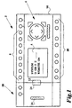
- Fig. 1 shows the structure of a communication system for performing the The inventive method in a preferred embodiment.
- the communication system includes a programmable electrical Switching device 2 with a computing unit, a screen 4, an operating unit 6, with signal inputs 8 and with signal outputs 10 and with one Data interface 12.
- the computing unit, the screen 4, the Control unit 6, the signal inputs 8 and the signal outputs 10 and Data interface 12 housed in a common housing 14.
- the Switching functions are carried out by the user via a menu-driven User interface programmable on the screen 4.
- the Programmable switching device 2 then switches under the control of one of the User programmable user program and depending on State of the signal inputs 8 the current flow between the signal inputs 8 and the signal outputs 10.
- the communication system includes one Expansion module 20 with one in a common housing 22 housed computing unit and with a data interface 24.
- Das Switching device 2 and the expansion module 20 are about their Data interfaces 12, 24 are mechanically and electrically connected to one another.
- the switching device 2 and the expansion module 20 formed such that after the expansion module 20 is connected the switching device 2 initiates a detection mode within the switching device 2 with a query whether the connected Expansion module 20 is initializable or not, is the Expansion module 20 cannot be initialized, there is no data exchange between switching device 2 and expansion module 20 (module is as "Foreign device" ignored); the expansion module 20 can be initialized, switches the switching device 2 into an expansion communication mode which the further data exchange under the control of the operating system of the Expansion module 20 takes place.
- the switching device 2 is used in connected expansion module 20 in a remote mode connected. This is free of the user via a menu item "REMOTE ON” selectable in the user interface. Selecting "REMOTE ON” will from this point in time the computing unit (CPU) of the switching device 2 from the Computer unit of the connected expansion module 20 controlled.
- an initializable expansion module 20 is used for this provided device interface 12 of the switching device 2 is recognized in a further procedural step is queried (via the BTS of the switching device), whether the initializable expansion module 20 is also configurable or Not.
- the other one can Data exchange (initialization and, if necessary, minimum configuration) be carried out fully automatically.
- the communication required for this is advantageously controlled entirely by the expansion module 20 itself.
- a controlled Data exchange between the two devices 2, 20 under the control of Computing unit of the expansion module 20 a controlled Data exchange.
- a storage unit e.g. EEPROM
- these must be in the expansion communication mode from the computing unit of the expansion module 20 be passed to the computing unit of the switching device 2.
- a Remote server functionality in the computing unit of the switching device 2 implemented, making appropriate services for example for input a subscriber address of the connected expansion module 20 or the input of parameters for the same via the control unit 6 of the Switching device 2 and the display of the entered address or parameter be made possible on the screen 4 of the switching device 2.
- the expansion module 20 has a corresponding interface 26 as well as software means for communication and connection to the bus system on. Then during the operation of the communication system Cyclic data exchange between Profibus and the computing unit of the Expansion module 20 performed.
- Figure 2 shows a schematic representation of the functional connection of the Expansion module 20 to the switching device 2.
- the operating system 30 with such an advantage that there is an operating system core 31 for the Coordination and execution of standard functions of switchgear 2 and some driver parts 32, 33 for data coordination of the input unit 6 and the display unit 8.
- the operating system 30 also a configurator part 34.
- This configurator part 34 acts in this way with the operating system kernel 31 together that over the device interface 12 communication with the connected expansion module 20 it is possible and preferably that the data of the Extension module 20 are changeable and / or can be entered into this and this process can be displayed on the display unit 4.
- the operating system kernel 31 of the switching device is controlled in a 2-controlled manner via the configurator part 34 - the data from the input unit 6 of the switching device 2 to the external expansion module 20 and from Extension module 20 for integrated display unit 8 of the switching device 2 only by.
- an expansion device 20 is connected to the switching device 2, then as soon as switching device 2 is switched on and remote mode is selected, the expansion module 20 from the operating system 30 of the switching device 2 recognized. If the expansion module 20 is not yet from the switching device 2 The system is locked and cannot be initialized Go to the "RUN" operating state. On the start menu of the switching device 2 a sub-item "REMOTE ON” appears. If the sub-item "REMOTE ON” An initialization run is selected by the operating system 30 (Data string is sent to expansion module 20). The Operating system 30 of the switching device 2 (more precisely the configurator part 10d) then receives from the expansion module 20 a data string for the Display unit 4.
- the Expansion module 20 via the configurator part 34 of the switching device 2 the control of the display unit 4 and the query of the input unit 6.
- the Data string sent by expansion module 20 contains user plain text information about required inputs and provides those for input required input masks are available.
- the configurator part 34 of the Operating system 30 of switching device 2 thus acts as a pure pass-through of the expansion module 20. Data checks such as value range checks and plausibility checks are the sole responsibility of the expansion module 20th
Landscapes
- Physics & Mathematics (AREA)
- General Physics & Mathematics (AREA)
- Engineering & Computer Science (AREA)
- Automation & Control Theory (AREA)
- Communication Control (AREA)
- Exchange Systems With Centralized Control (AREA)
- Logic Circuits (AREA)
- Programmable Controllers (AREA)
Abstract
- initierung eines Erkennungsmodus innerhalb des Schaltegerätes (2), wobei eine Abfrage erfolgt, ob die angeschlossene Erweiterungsbaugruppe (20) initialisierbar ist oder nicht,
- ist die Erweiterungsbaugruppe (20) nicht initialisierbar erfolgt kein Datenaustausch zwischen Schaltgerät (2) und Erweiterungsbaugruppe (20), ist die Erweiterungsbaugruppe (20) initialisierbar, schaltet das Schaltgerät (2) in einen Erweiterungs-Kommunikationsmodus in dem der weitere Datenaustausch unter Kontrolle des Betriebssystems der Erweiterungsbaugruppe (20) erfolgt.
Description
- Figur 1:
- ein Kommunikationssystem zur Durchführung des erfindungsgemäßen Verfahrens, umfassend ein Schaltgerät mit angeschlossener Erweiterungsbaugruppe in schematischer Darstellung; und
- Figur 2:
- eine Schaltgerätekombination gemäß Figur 1 in einer bevorzugten Ausführungsform;
- LÖSCHE DISPLAY, bereitet eine Zeichenausgabe vor;
- SETZE CURSOR, positioniert den Cursor im Displayfeld;
- GIB ZEICHEN AUS, schreibt ein ASCII-Zeichen an der momentanen Cursorposition und inkrementiert dieses;
- HOLE INTEGERWERT, wartet auf die Übemahme des im Display eingestellten Wertes (Übernahme z.B, durch Betätigung einer Freigabetaste);
- REMOTE OFF, verlässt den Konfigurationsmodus.
Claims (2)
- Verfahren zum Anschluß einer Erweiterungsbaugruppe (20) an ein programmierbares elektrisches Schaltgerät (2), wobeidas Schaltgerät (2) eine Recheneinheit, einen Bildschirm (4), eine Bedieneinheit (6) und Signaleingänge (8) und Signalausgänge (10) sowie eine Datenschnittstelle (12) umfasst und die Recheneinheit, der Bildschirm (4), die Bedieneinheit (6), die Signaleingänge (8) und die Signalausgänge (10) sowie die Datenschnittstelle (12) in einem gemeinsamen Gehäuse (14) untergebracht sind und wobei Schaltfunktionen durch den Benutzer über eine menügeführte Benutzeroberfläche auf dem Bildschirm (4) programmierbar sind und das programmierbare Schaltgerät unter Kontrolle eines Anwenderprogramms und in Abhängigkeit vom Zustand der Signaleingänge (8) den Stromfluß zwischen den Signaleingängen (8) und den Signalausgängen (10) schaltet, und wobeidie Erweiterungsbaugruppe (20) eine in einem gemeinsamen Gehäuse (22) untergebrachte Recheneinheit und eine Datenschnittstelle (24) umfasstund das Schaltgerät (2) und die Erweiterungsbaugruppe (20) zwecks Datenaustausch über ihre Datenschnittstellen (12, 24) miteinander verbunden sind, mit folgenden Verfahrensschritten:Initiierung eines Erkennungsmodus innerhalb des Schaltgerätes (2), wobei eine Abfrage erfolgt, ob die angeschlossene Erweiterungsbaugruppe (20) initialisierbar ist oder nicht,ist die Erweiterungsbaugruppe (20) nicht initialisierbar erfolgt kein Datenaustausch zwischen Schaltgerät (2) und Erweiterungsbaugruppe (20), ist die Erweiterungsbaugruppe (20) initiallslerbar, schaltet das Schaltgerät (2) in einen Erweiterungs-Kommunikationsmodus in dem der weitere Datenaustausch unter Kontrolle des Betriebssystems der Erweiterungsbaugruppe (20) erfolgt.
- Verfahren nach vorstehendem Anspruch, dadurch gekennzeichnet, dass in einem weiteren Verfahrensschritt abgefragt wird, ob die initialisierbare Erweiterungsbaugruppe (20) konfigurierbar ist oder nicht und für den Fall, dass sie konfigurierbar ist, in dem Erweiterungs-Kommunikationsmodus die Recheneinheit des Schaltgerätes (2) von der Recheneinheit der Erweiterungsbaugruppe (20) gesteuert wird derart, dass die Bedieneinheit (6) und der Bildschirm (4) des Schaltgerätes (2) von diesem funktional entkoppelbar und mit der Erweiterungsbaugruppe (20) koppelbar sind.
Applications Claiming Priority (2)
| Application Number | Priority Date | Filing Date | Title |
|---|---|---|---|
| DE10043841 | 2000-09-06 | ||
| DE10043841A DE10043841A1 (de) | 2000-09-06 | 2000-09-06 | Verfahren zum Anschluss einer Erweiterungsbaugruppe an ein programmierbares elektrisches Schaltgerät |
Publications (3)
| Publication Number | Publication Date |
|---|---|
| EP1186972A2 true EP1186972A2 (de) | 2002-03-13 |
| EP1186972A3 EP1186972A3 (de) | 2005-04-20 |
| EP1186972B1 EP1186972B1 (de) | 2008-02-27 |
Family
ID=7655145
Family Applications (1)
| Application Number | Title | Priority Date | Filing Date |
|---|---|---|---|
| EP01121320A Expired - Lifetime EP1186972B1 (de) | 2000-09-06 | 2001-09-06 | Verfahren zur Initialisierung einer Erweiterungsbaugruppe an ein programmierbares elektrisches Schaltgerät |
Country Status (4)
| Country | Link |
|---|---|
| US (1) | US7107379B2 (de) |
| EP (1) | EP1186972B1 (de) |
| AT (1) | ATE387648T1 (de) |
| DE (2) | DE10043841A1 (de) |
Cited By (3)
| Publication number | Priority date | Publication date | Assignee | Title |
|---|---|---|---|---|
| EP1785971A2 (de) | 2005-11-09 | 2007-05-16 | Hager Electro GmbH & Co. KG | Anzeigevorrichtung für elektrische Verteiler |
| EP2063332A1 (de) * | 2007-11-21 | 2009-05-27 | Pepperl + Fuchs Gmbh | Sensor für die Automatisierungstechnik und Verfahren zum Übermitteln von Konfigurationsdaten von einem externen Rechner an einen Sensor |
| CN108036518A (zh) * | 2018-01-02 | 2018-05-15 | 成都前锋电子有限责任公司 | 一种燃气快速热水器兼容性可扩展通讯系统 |
Families Citing this family (7)
| Publication number | Priority date | Publication date | Assignee | Title |
|---|---|---|---|---|
| DE10355790B4 (de) * | 2003-11-26 | 2006-07-13 | Senstronic Deutschland Gmbh | Verteiler für die Automatisierung mit einem Speichermodul hierfür |
| US20070173961A1 (en) * | 2006-01-22 | 2007-07-26 | Shalabh Kumar | Automation controller with integrated hmi and modular i/o |
| DE102007038061A1 (de) | 2007-08-10 | 2009-02-12 | Endress + Hauser Gmbh + Co. Kg | Modular aufgebautes Feldgerät der Prozessautomatisierungstechnik |
| US20110224810A1 (en) * | 2010-03-12 | 2011-09-15 | Spansion Llc | Home and building automation |
| US20110225327A1 (en) * | 2010-03-12 | 2011-09-15 | Spansion Llc | Systems and methods for controlling an electronic device |
| TWI477970B (zh) * | 2012-08-24 | 2015-03-21 | Realtek Semiconductor Corp | 電子裝置的模式切換方法與相關的電子裝置 |
| CN105518240A (zh) | 2013-09-09 | 2016-04-20 | 美国耶鲁安全公司 | 用于增加在门操作器上的数字输入部和输出部的范围的方法和设备 |
Family Cites Families (9)
| Publication number | Priority date | Publication date | Assignee | Title |
|---|---|---|---|---|
| DE3828916A1 (de) * | 1988-08-26 | 1990-03-01 | Broadcast Television Syst | Verfahren zur konfigurierung der beschaltung von speicherschaltungen in einem mikrocomputersystem |
| EP0434986A3 (en) | 1989-12-22 | 1993-06-16 | Siemens Aktiengesellschaft | Method for putting into operation a module connected to an electronic control system |
| US5237690A (en) * | 1990-07-06 | 1993-08-17 | International Business Machines Corporation | System for testing adaptor card upon power up and having disablement, enablement, and reconfiguration options |
| JPH0736175B2 (ja) | 1991-10-11 | 1995-04-19 | インターナショナル・ビジネス・マシーンズ・コーポレイション | データ処理システムのシステム構成設定方法、データ処理システム、及びデータ処理システム用拡張ユニット |
| US5668992A (en) * | 1994-08-01 | 1997-09-16 | International Business Machines Corporation | Self-configuring computer system |
| DE19629055C2 (de) * | 1996-07-18 | 1998-05-28 | Siemens Ag | Verfahren zum Herstellen eines Startzustandes bezüglich einer Schnittstelle durch zwei identische Befehlsfolgen |
| US6016523A (en) * | 1998-03-09 | 2000-01-18 | Schneider Automation, Inc. | I/O modular terminal having a plurality of data registers and an identification register and providing for interfacing between field devices and a field master |
| DE19812423A1 (de) | 1998-03-20 | 1999-09-23 | Moeller Gmbh | Bedientasten als aktive Tasten |
| EP1177482A1 (de) * | 1999-03-15 | 2002-02-06 | Siemens Energy & Automation, Inc. | Eingangsfilterschaltung für eine logisch programmierbare steuerung und zugehöriges verfahren |
-
2000
- 2000-09-06 DE DE10043841A patent/DE10043841A1/de not_active Withdrawn
-
2001
- 2001-09-05 US US09/947,333 patent/US7107379B2/en not_active Expired - Fee Related
- 2001-09-06 AT AT01121320T patent/ATE387648T1/de active
- 2001-09-06 EP EP01121320A patent/EP1186972B1/de not_active Expired - Lifetime
- 2001-09-06 DE DE50113652T patent/DE50113652D1/de not_active Expired - Lifetime
Cited By (6)
| Publication number | Priority date | Publication date | Assignee | Title |
|---|---|---|---|---|
| EP1785971A2 (de) | 2005-11-09 | 2007-05-16 | Hager Electro GmbH & Co. KG | Anzeigevorrichtung für elektrische Verteiler |
| EP1785971A3 (de) * | 2005-11-09 | 2008-06-18 | Hager Electro GmbH & Co. KG | Anzeigevorrichtung für elektrische Verteiler |
| EP2063332A1 (de) * | 2007-11-21 | 2009-05-27 | Pepperl + Fuchs Gmbh | Sensor für die Automatisierungstechnik und Verfahren zum Übermitteln von Konfigurationsdaten von einem externen Rechner an einen Sensor |
| WO2009065593A3 (de) * | 2007-11-21 | 2009-07-09 | Pepperl & Fuchs | Sensor für die automatisierungstechnik und verfahren zum übermitteln von konfigurationsdaten von einem externen rechner an einen sensor |
| CN108036518A (zh) * | 2018-01-02 | 2018-05-15 | 成都前锋电子有限责任公司 | 一种燃气快速热水器兼容性可扩展通讯系统 |
| CN108036518B (zh) * | 2018-01-02 | 2023-07-25 | 成都前锋电子有限责任公司 | 一种燃气快速热水器兼容性可扩展通讯系统 |
Also Published As
| Publication number | Publication date |
|---|---|
| EP1186972A3 (de) | 2005-04-20 |
| US7107379B2 (en) | 2006-09-12 |
| EP1186972B1 (de) | 2008-02-27 |
| ATE387648T1 (de) | 2008-03-15 |
| DE10043841A1 (de) | 2002-03-14 |
| US20020073266A1 (en) | 2002-06-13 |
| DE50113652D1 (de) | 2008-04-10 |
Similar Documents
| Publication | Publication Date | Title |
|---|---|---|
| DE69705999T2 (de) | Graphische Benutzerschnittstelle für die Programmierung einer Motorsteuerung | |
| DE60011770T2 (de) | Verfahren und vorrichtung zur navigation mit verschiebbaren kreuzungspunkten in einer benutzerschnittstelle | |
| DE69308942T2 (de) | Steuerungseinrichtung mit Übermittlung von Steuerungsstrukturdefinitionen | |
| EP1096348A1 (de) | Integration eines Feldleitgerätes in ein Anlagenleitsystem | |
| EP1186972B1 (de) | Verfahren zur Initialisierung einer Erweiterungsbaugruppe an ein programmierbares elektrisches Schaltgerät | |
| EP1199846A1 (de) | Verfahren zur automatischen Gerätekonfiguration in einem Feldbus-System | |
| EP1751635A1 (de) | System zum bedienen einer anlage durch editieren von grafischen objekten | |
| EP1233317B1 (de) | Vorrichtung und Verfahren zur Erstellung von Bedienungskomponenten | |
| EP1005215B1 (de) | Verfahren und Vorrichtung zum Editieren von Konfigurationsdaten für Telekommunikationssysteme | |
| WO2005022286A2 (de) | Verfahren zur graphischen projektierung der steuerung einer technischen anlage mit integrierter projektierung von bediengeräten, einschliesslich einem projektierungssystem und einem computerprogrammprodukt | |
| WO2010111989A1 (de) | Vorrichtung, verfahren und computerprogrammprodukt zum darstellen einer aktuellen taskliste auf der graphischen benutzeroberfläche eines steuerungscomputers einer bearbeitungsmaschine | |
| EP0862763B1 (de) | Simulatoreinheit zum simulieren einer peripherieeinheit einer modular aufgebauten speicherprogrammierbaren steuerung | |
| EP1217476A2 (de) | Vorrichtung und Verfahren zur Inbetriebnahme und Diagnose von Steuerungssystemen | |
| DE3319130C2 (de) | Programmierbare Steuerung | |
| DE10254152A1 (de) | Verfahren zum Datenaustausch zwischen einem elektrischen Gerät und einer Benutzerschnittstelle über ein Datennetz | |
| DE4009074C2 (de) | ||
| WO2011064046A1 (de) | Feldgerät mit einer anzeigeeinheit und verfahren zum betreiben der anzeigeeinheit | |
| EP1547309B1 (de) | Verfahren zur aktualisierung des lokalen managementsystems in mindestens einem netzelement eines telekommunikationsnetzwerkes | |
| EP1183577B1 (de) | Verfahren zur erzeugung eines steuerbausteins und steuerbaustein | |
| DE10245890A1 (de) | Bildschirmelement zur Visualisierung und Projektierung von einfach und mehrfach verwendeten Anwendertexten in einem Datenverarbeitungssystem | |
| EP0608762B1 (de) | Verfahren zur Einbindung unscharfer Logik in den Funktionsumfang standardisierter Automatisierungssysteme | |
| EP1752896B1 (de) | Grafische Verschaltung von Hardware-Signalen | |
| EP1513034B9 (de) | Online aktualisierbares Bediengerät (BAE) für einen Umrichter | |
| EP1096349A1 (de) | Konfiguration eines Anlagenleitsystems | |
| EP4086754A1 (de) | Verfahren zur rechnergestützten konfiguration eines endgeräts, endgerät und betriebsverfahren für das endgerät |
Legal Events
| Date | Code | Title | Description |
|---|---|---|---|
| PUAI | Public reference made under article 153(3) epc to a published international application that has entered the european phase |
Free format text: ORIGINAL CODE: 0009012 |
|
| AK | Designated contracting states |
Kind code of ref document: A2 Designated state(s): AT BE CH CY DE DK ES FI FR GB GR IE IT LI LU MC NL PT SE TR |
|
| AX | Request for extension of the european patent |
Free format text: AL;LT;LV;MK;RO;SI |
|
| PUAL | Search report despatched |
Free format text: ORIGINAL CODE: 0009013 |
|
| AK | Designated contracting states |
Kind code of ref document: A3 Designated state(s): AT BE CH CY DE DK ES FI FR GB GR IE IT LI LU MC NL PT SE TR |
|
| AX | Request for extension of the european patent |
Extension state: AL LT LV MK RO SI |
|
| 17P | Request for examination filed |
Effective date: 20050326 |
|
| AKX | Designation fees paid |
Designated state(s): AT BE CH CY DE DK ES FI FR GB GR IE IT LI LU MC NL PT SE TR |
|
| 17Q | First examination report despatched |
Effective date: 20070319 |
|
| RTI1 | Title (correction) |
Free format text: METHOD OF INITILISATION OF AN EXTENSION BOARD IN A PROGRAMMABLE ELECTRICAL SWITCHING DEVICE |
|
| GRAP | Despatch of communication of intention to grant a patent |
Free format text: ORIGINAL CODE: EPIDOSNIGR1 |
|
| GRAS | Grant fee paid |
Free format text: ORIGINAL CODE: EPIDOSNIGR3 |
|
| GRAA | (expected) grant |
Free format text: ORIGINAL CODE: 0009210 |
|
| AK | Designated contracting states |
Kind code of ref document: B1 Designated state(s): AT BE CH CY DE DK ES FI FR GB GR IE IT LI LU MC NL PT SE TR |
|
| REG | Reference to a national code |
Ref country code: GB Ref legal event code: FG4D Free format text: NOT ENGLISH |
|
| REG | Reference to a national code |
Ref country code: CH Ref legal event code: EP |
|
| REG | Reference to a national code |
Ref country code: IE Ref legal event code: FG4D Free format text: LANGUAGE OF EP DOCUMENT: GERMAN |
|
| REF | Corresponds to: |
Ref document number: 50113652 Country of ref document: DE Date of ref document: 20080410 Kind code of ref document: P |
|
| PG25 | Lapsed in a contracting state [announced via postgrant information from national office to epo] |
Ref country code: ES Free format text: LAPSE BECAUSE OF FAILURE TO SUBMIT A TRANSLATION OF THE DESCRIPTION OR TO PAY THE FEE WITHIN THE PRESCRIBED TIME-LIMIT Effective date: 20080607 |
|
| NLV1 | Nl: lapsed or annulled due to failure to fulfill the requirements of art. 29p and 29m of the patents act | ||
| REG | Reference to a national code |
Ref country code: IE Ref legal event code: FD4D |
|
| PG25 | Lapsed in a contracting state [announced via postgrant information from national office to epo] |
Ref country code: NL Free format text: LAPSE BECAUSE OF FAILURE TO SUBMIT A TRANSLATION OF THE DESCRIPTION OR TO PAY THE FEE WITHIN THE PRESCRIBED TIME-LIMIT Effective date: 20080227 Ref country code: SE Free format text: LAPSE BECAUSE OF FAILURE TO SUBMIT A TRANSLATION OF THE DESCRIPTION OR TO PAY THE FEE WITHIN THE PRESCRIBED TIME-LIMIT Effective date: 20080527 Ref country code: DK Free format text: LAPSE BECAUSE OF FAILURE TO SUBMIT A TRANSLATION OF THE DESCRIPTION OR TO PAY THE FEE WITHIN THE PRESCRIBED TIME-LIMIT Effective date: 20080227 Ref country code: IE Free format text: LAPSE BECAUSE OF FAILURE TO SUBMIT A TRANSLATION OF THE DESCRIPTION OR TO PAY THE FEE WITHIN THE PRESCRIBED TIME-LIMIT Effective date: 20080227 Ref country code: PT Free format text: LAPSE BECAUSE OF FAILURE TO SUBMIT A TRANSLATION OF THE DESCRIPTION OR TO PAY THE FEE WITHIN THE PRESCRIBED TIME-LIMIT Effective date: 20080721 |
|
| ET | Fr: translation filed | ||
| PLBE | No opposition filed within time limit |
Free format text: ORIGINAL CODE: 0009261 |
|
| STAA | Information on the status of an ep patent application or granted ep patent |
Free format text: STATUS: NO OPPOSITION FILED WITHIN TIME LIMIT |
|
| 26N | No opposition filed |
Effective date: 20081128 |
|
| BERE | Be: lapsed |
Owner name: MOELLER G.M.B.H. Effective date: 20080930 |
|
| PG25 | Lapsed in a contracting state [announced via postgrant information from national office to epo] |
Ref country code: MC Free format text: LAPSE BECAUSE OF NON-PAYMENT OF DUE FEES Effective date: 20080930 |
|
| REG | Reference to a national code |
Ref country code: CH Ref legal event code: PL |
|
| PG25 | Lapsed in a contracting state [announced via postgrant information from national office to epo] |
Ref country code: BE Free format text: LAPSE BECAUSE OF NON-PAYMENT OF DUE FEES Effective date: 20080930 Ref country code: CY Free format text: LAPSE BECAUSE OF FAILURE TO SUBMIT A TRANSLATION OF THE DESCRIPTION OR TO PAY THE FEE WITHIN THE PRESCRIBED TIME-LIMIT Effective date: 20080227 |
|
| PG25 | Lapsed in a contracting state [announced via postgrant information from national office to epo] |
Ref country code: LI Free format text: LAPSE BECAUSE OF NON-PAYMENT OF DUE FEES Effective date: 20080930 Ref country code: CH Free format text: LAPSE BECAUSE OF NON-PAYMENT OF DUE FEES Effective date: 20080930 |
|
| PG25 | Lapsed in a contracting state [announced via postgrant information from national office to epo] |
Ref country code: LU Free format text: LAPSE BECAUSE OF NON-PAYMENT OF DUE FEES Effective date: 20080906 |
|
| PG25 | Lapsed in a contracting state [announced via postgrant information from national office to epo] |
Ref country code: TR Free format text: LAPSE BECAUSE OF FAILURE TO SUBMIT A TRANSLATION OF THE DESCRIPTION OR TO PAY THE FEE WITHIN THE PRESCRIBED TIME-LIMIT Effective date: 20080227 |
|
| PG25 | Lapsed in a contracting state [announced via postgrant information from national office to epo] |
Ref country code: GR Free format text: LAPSE BECAUSE OF FAILURE TO SUBMIT A TRANSLATION OF THE DESCRIPTION OR TO PAY THE FEE WITHIN THE PRESCRIBED TIME-LIMIT Effective date: 20080528 |
|
| PGFP | Annual fee paid to national office [announced via postgrant information from national office to epo] |
Ref country code: FI Payment date: 20130909 Year of fee payment: 13 |
|
| PG25 | Lapsed in a contracting state [announced via postgrant information from national office to epo] |
Ref country code: FI Free format text: LAPSE BECAUSE OF NON-PAYMENT OF DUE FEES Effective date: 20140906 |
|
| REG | Reference to a national code |
Ref country code: FR Ref legal event code: PLFP Year of fee payment: 16 |
|
| REG | Reference to a national code |
Ref country code: FR Ref legal event code: PLFP Year of fee payment: 17 |
|
| PGFP | Annual fee paid to national office [announced via postgrant information from national office to epo] |
Ref country code: GB Payment date: 20170829 Year of fee payment: 17 Ref country code: IT Payment date: 20170913 Year of fee payment: 17 Ref country code: FR Payment date: 20170823 Year of fee payment: 17 |
|
| PGFP | Annual fee paid to national office [announced via postgrant information from national office to epo] |
Ref country code: AT Payment date: 20170828 Year of fee payment: 17 |
|
| PGFP | Annual fee paid to national office [announced via postgrant information from national office to epo] |
Ref country code: DE Payment date: 20170928 Year of fee payment: 17 |
|
| REG | Reference to a national code |
Ref country code: DE Ref legal event code: R119 Ref document number: 50113652 Country of ref document: DE |
|
| REG | Reference to a national code |
Ref country code: AT Ref legal event code: MM01 Ref document number: 387648 Country of ref document: AT Kind code of ref document: T Effective date: 20180906 |
|
| GBPC | Gb: european patent ceased through non-payment of renewal fee |
Effective date: 20180906 |
|
| PG25 | Lapsed in a contracting state [announced via postgrant information from national office to epo] |
Ref country code: IT Free format text: LAPSE BECAUSE OF NON-PAYMENT OF DUE FEES Effective date: 20180906 Ref country code: DE Free format text: LAPSE BECAUSE OF NON-PAYMENT OF DUE FEES Effective date: 20190402 |
|
| PG25 | Lapsed in a contracting state [announced via postgrant information from national office to epo] |
Ref country code: FR Free format text: LAPSE BECAUSE OF NON-PAYMENT OF DUE FEES Effective date: 20180930 |
|
| PG25 | Lapsed in a contracting state [announced via postgrant information from national office to epo] |
Ref country code: GB Free format text: LAPSE BECAUSE OF NON-PAYMENT OF DUE FEES Effective date: 20180906 Ref country code: AT Free format text: LAPSE BECAUSE OF NON-PAYMENT OF DUE FEES Effective date: 20180906 |