EP1186659A1 - Nucleotide detector, process for producing the same and process for forming fine particle membrane - Google Patents
Nucleotide detector, process for producing the same and process for forming fine particle membrane Download PDFInfo
- Publication number
- EP1186659A1 EP1186659A1 EP01912416A EP01912416A EP1186659A1 EP 1186659 A1 EP1186659 A1 EP 1186659A1 EP 01912416 A EP01912416 A EP 01912416A EP 01912416 A EP01912416 A EP 01912416A EP 1186659 A1 EP1186659 A1 EP 1186659A1
- Authority
- EP
- European Patent Office
- Prior art keywords
- substrate
- particles
- liquid
- dna
- dnas
- Prior art date
- Legal status (The legal status is an assumption and is not a legal conclusion. Google has not performed a legal analysis and makes no representation as to the accuracy of the status listed.)
- Withdrawn
Links
Images








Classifications
-
- C—CHEMISTRY; METALLURGY
- C12—BIOCHEMISTRY; BEER; SPIRITS; WINE; VINEGAR; MICROBIOLOGY; ENZYMOLOGY; MUTATION OR GENETIC ENGINEERING
- C12Q—MEASURING OR TESTING PROCESSES INVOLVING ENZYMES, NUCLEIC ACIDS OR MICROORGANISMS; COMPOSITIONS OR TEST PAPERS THEREFOR; PROCESSES OF PREPARING SUCH COMPOSITIONS; CONDITION-RESPONSIVE CONTROL IN MICROBIOLOGICAL OR ENZYMOLOGICAL PROCESSES
- C12Q1/00—Measuring or testing processes involving enzymes, nucleic acids or microorganisms; Compositions therefor; Processes of preparing such compositions
- C12Q1/68—Measuring or testing processes involving enzymes, nucleic acids or microorganisms; Compositions therefor; Processes of preparing such compositions involving nucleic acids
- C12Q1/6813—Hybridisation assays
- C12Q1/6816—Hybridisation assays characterised by the detection means
- C12Q1/6825—Nucleic acid detection involving sensors
-
- C—CHEMISTRY; METALLURGY
- C12—BIOCHEMISTRY; BEER; SPIRITS; WINE; VINEGAR; MICROBIOLOGY; ENZYMOLOGY; MUTATION OR GENETIC ENGINEERING
- C12Q—MEASURING OR TESTING PROCESSES INVOLVING ENZYMES, NUCLEIC ACIDS OR MICROORGANISMS; COMPOSITIONS OR TEST PAPERS THEREFOR; PROCESSES OF PREPARING SUCH COMPOSITIONS; CONDITION-RESPONSIVE CONTROL IN MICROBIOLOGICAL OR ENZYMOLOGICAL PROCESSES
- C12Q1/00—Measuring or testing processes involving enzymes, nucleic acids or microorganisms; Compositions therefor; Processes of preparing such compositions
- C12Q1/68—Measuring or testing processes involving enzymes, nucleic acids or microorganisms; Compositions therefor; Processes of preparing such compositions involving nucleic acids
- C12Q1/6813—Hybridisation assays
- C12Q1/6834—Enzymatic or biochemical coupling of nucleic acids to a solid phase
- C12Q1/6837—Enzymatic or biochemical coupling of nucleic acids to a solid phase using probe arrays or probe chips
-
- B—PERFORMING OPERATIONS; TRANSPORTING
- B01—PHYSICAL OR CHEMICAL PROCESSES OR APPARATUS IN GENERAL
- B01J—CHEMICAL OR PHYSICAL PROCESSES, e.g. CATALYSIS OR COLLOID CHEMISTRY; THEIR RELEVANT APPARATUS
- B01J2219/00—Chemical, physical or physico-chemical processes in general; Their relevant apparatus
- B01J2219/00274—Sequential or parallel reactions; Apparatus and devices for combinatorial chemistry or for making arrays; Chemical library technology
- B01J2219/00583—Features relative to the processes being carried out
- B01J2219/00603—Making arrays on substantially continuous surfaces
- B01J2219/00646—Making arrays on substantially continuous surfaces the compounds being bound to beads immobilised on the solid supports
- B01J2219/00648—Making arrays on substantially continuous surfaces the compounds being bound to beads immobilised on the solid supports by the use of solid beads
-
- B—PERFORMING OPERATIONS; TRANSPORTING
- B01—PHYSICAL OR CHEMICAL PROCESSES OR APPARATUS IN GENERAL
- B01J—CHEMICAL OR PHYSICAL PROCESSES, e.g. CATALYSIS OR COLLOID CHEMISTRY; THEIR RELEVANT APPARATUS
- B01J2219/00—Chemical, physical or physico-chemical processes in general; Their relevant apparatus
- B01J2219/00274—Sequential or parallel reactions; Apparatus and devices for combinatorial chemistry or for making arrays; Chemical library technology
- B01J2219/00718—Type of compounds synthesised
- B01J2219/0072—Organic compounds
- B01J2219/00722—Nucleotides
-
- C—CHEMISTRY; METALLURGY
- C40—COMBINATORIAL TECHNOLOGY
- C40B—COMBINATORIAL CHEMISTRY; LIBRARIES, e.g. CHEMICAL LIBRARIES
- C40B40/00—Libraries per se, e.g. arrays, mixtures
- C40B40/04—Libraries containing only organic compounds
- C40B40/06—Libraries containing nucleotides or polynucleotides, or derivatives thereof
Definitions
- the present invention relates to a technology for using a film made of particulates placed with high precision, and more particularly, to a technology used suitably for manufacture of a nucleotide detector and the like.
- the genome DNA sequence (base sequence (gene arrangement)) concerned is a genome DMA sequence of a specific person, and not that of an individual.
- the genome DNA sequence of an individual is slightly different from that of the specific person, where substitution, deletion, insertion, and the like of a base may have occurred in a gene. Normally, such a slight difference is not critical and does not cause any trouble in the life of the individual.
- the basics in detection of the DNA sequence of a gene of an individual are that the DNA sequence of a target gene has been determined and that how the gene of the individual is different from the so-called human gene DNA sequence is sought, as in the instance of sickle cell anemia described above.
- first, 1000 types of single-stranded DNAs slightly different from the human gene DNA sequence (base sequence) are synthesized in advance, and placed on a substrate.
- One type of DNA is placed on one section of the substrate, and the position is recorded.
- DNA of the subject is taken, and the double helix structure of the DNA is released into single-stranded DNAs.
- the DNA is then cut into pieces of an appropriate length, and the DNA pieces are fluorescence-labeled.
- the fluorescence-labeled DNAs are allowed to hybridize (conjugate) with the single-stranded DNAs placed in advance on the substrate.
- any position/section of the substrate that emits fluorescence is detected.
- the DNA placed in advance in the section that emits fluorescence is determined to be the DNA sequence that has hybridized with the DNA of the subject. In other words, by detecting the position emitting fluorescence, it is clarified in a short time how the DNA sequence of the subject has mutated from the human gene DNA sequence.
- particulates have a large ratio of the surface area to the volume, and therefore exhibit behaviors generally different from materials that are small in this ratio.
- particulates of an inorganic material such as titanium oxide and zinc oxide have ultraviolet removal function, antimicrobial function, catalytic function, and the like.
- particulates of an inorganic material those having a diameter of the order of nanometers (ultra-fine particles) are expected to provide a quantum effect.
- Particulates of protein having a diameter of about 10 to 20 nm have received attention for their use for biosensors and the like.
- particle capable of containing an inorganic material inside are provided with natures of both the inorganic material and the protein particles.
- the particulates described above are normally available in the form of a colloid solution.
- the form of a colloid solution is disadvantageous when the functions of the particulates are to be effectively used. Therefore, search has been made for a technique that permits effective use of the functions of the particulates in the industrial field using the colloid solution as a raw material.
- Nagayama et al. have disclosed the following method in "Formation of Holoferritin Hexagonal Arrays in Secondary Films Due To Alder-Type Transition", Lanbgmuir 1996, vol. 12, pp. 1836-1839. That is, as shown in FIG. 18 , a substrate 11 is put in a solution 18 containing particulates 15 (polystyrene spheres having a diameter of about 1 to 2 ⁇ m) dispersed therein, and then gradually lifted in the position vertical to the liquid level, forming a wet film 19 on both surfaces of the substrate 11 . In this way, a film made of polystyrene spheres having a diameter of about 1 to 2 ⁇ m is formed on the surfaces of the substrate 11 .
- particulates 15 polystyrene spheres having a diameter of about 1 to 2 ⁇ m
- FIG. 16 is a view illustrating the method for forming a two-dimensional crystal film made of ferritin.
- a platinum blade 21 is placed in the position vertical to the surface of a substrate 11 that is mounted on a base 20 .
- a liquid 16 containing ferritin dispersed therein is then dropped into a small space between the substrate 11 and the blade 21 , so that the liquid 16 is held in and around the space (hatched portion in FIG. 16 ) due to the surface tension of the liquid 16 .
- the base 20 that is, the substrate 11
- the base 20 that is, the substrate 11
- a constant speed (2 ⁇ m/sec. in this case).
- the liquid 16 being applied to the substrate 11 .
- the water content of the liquid 16 is evaporated gradually as the liquid 16 is sequentially applied to the substrate 11 , allowing formation of a thin film 22 made of ferritin.
- the thin film 22 has a thickness of about 10 layers of ferritin particles.
- the DNA chip causes various problems. To state specifically, if the density of DNAs placed in a certain section is too low, the intensity of fluorescence emitted from hybridized DNAs decreases, deteriorating the signal to noise (SN) ratio. In other words, the fluorescence from hybridized DNAs may possibly be buried in background fluorescence inevitably generated.
- SN signal to noise
- the absolute amount of DNAs placed varies with the sections, a plurality of sections may emit fluorescence at different intensities when the DNA of the subject hybridizes in two or more sections. In this event, it is unknown why the fluorescence intensity is low in one section compared with that in another section. Specifically, it is difficult to determine whether the fluorescence intensity is low because the absolute amount of DNA placed is small or because the absolute amount DNA placed is so large that emission of fluorescence is allowed despite of weak nonspecific adsorption. This may results in mistake of the determination. Furthermore, the variation in the absolute amount of DNAs placed among chips indicates that the reproducibility of the chip quality is poor. This may results in generation of defective DNA chips.
- An object of the present invention is to provide a nucleotide detector capable of detecting target nucleotide (DNA, RNA, or the like) with high precision.
- Another object of the present invention is to provide a method for easily producing a two-dimensional crystal film made of particulates of protein or the like having a diameter of the order of nanometers arranged at high density and at desired positions with high precision.
- the nucleotide detector of the present invention includes: a substrate; metal particles placed regularly on the substrate; and one of a pair of nucleotide molecules capable of conjugating with each other, the one nucleotide molecule being bonded to each of the metal particles.
- Either one of a pair of nucleotide molecules capable of conjugating with each other is bonded to each of the metal particles placed regularly on the substrate. Therefore, the conjugation between the one nucleotide molecule and the other nucleotide molecule capable of conjugating with the former can be established in uniform over the substrate. Thus, when the other nucleotide molecule is made detectable with a fluorescent label or the like, for example, a stable detection signal can be obtained.
- the method for manufacturing a nucleotide detector of the present invention includes the steps of: (a) arranging complex particles each including a metal particle and a protein molecule holding the metal particle on a substrate; (b) removing the protein molecules; and (c) bonding one of a pair of nucleotide molecules capable of conjugating with each other to each of the metal particles left on the substrate in the step (b).
- nucleotide detector in which nucleotide molecules constituting one of a pair of nucleotide molecules capable of conjugating with each other are regularly placed on the substrate.
- the protein molecules may be Dps protein or apoferritin.
- the nucleotide molecules may be a plurality of types of nucleotide molecules having different base sequences.
- the method for producing a particulate film of the present invention includes the steps of: (a) placing a substrate in a container so that a surface of the substrate is vertical to the liquid level of a liquid containing particulates filled in the container; and (b) raising or lowering the liquid level of the liquid.
- the liquid level slightly rises along the substrate at the interface between the liquid and the substrate, forming a meniscus portion. Since the meniscus portion has a large surface area, a dispersion medium of the liquid evaporates, resulting in reduction of the amount of the dispersion medium in the meniscus portion. This causes an effect similar to the micro-capillary effect in the meniscus portion, where the liquid flows toward this portion. As a result, the particles exist in the meniscus portion of the liquid in a significantly high concentration, and thus are arranged on the surface of the substrate at high density with high precision. In other words, a film of particulates arranged at high density with high precision is formed on the surface of the substrate.
- the method for producing a particulate film of the present invention is particularly preferable when the particulates have a diameter of 50 nm or less.
- the particulates may be protein.
- the protein may contain an inorganic material inside.
- the concentration of the protein in the liquid is preferably 10 ⁇ g/ml to 500 mg/ml.
- the liquid may contain an electrolyte.
- a liquid level raising or lowering rate of the liquid is substantially constant, and it is 10 mm/min. or less.
- the liquid may be allowed to flow out by gravity.
- the substrate may have a convex and concave pattern on a surface.
- nucleotides such as DNAs and RNAs as used herein are single-stranded unless otherwise specified.
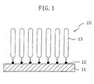
- a nucleotide detector 10 of this embodiment is a DNA sensor, which includes a substrate 11 , gold particles 12 having a size of the order of nanometers (diameter of about 6 nm) placed on a surface of the substrate 11 at high density with high precision (with spaces of about 12 nm between adjacent particles), and single-stranded DNAs (thiol DNAs) 13 each having a sulfur atom at an end.
- the thiol DNAs 13 are bonded to the gold particles 12 .
- a method for manufacturing the nucleotide detector 10 of this embodiment will be described with reference to the relevant drawings.
- the nucleotide detector 10 of this embodiment it is necessary to place the gold particles 12 having a diameter of about 6 nm on a surface of the substrate 11 at high density with high precision. In other words, it is necessary to arrange and immobilize the gold particles 12 two-dimensionally on a surface of the substrate 11 .
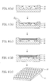
- complex particles 15 each composed of a protein molecule 14 holding the gold particle 12 are prepared and placed on the surface of the substrate 11 , to thereby form a complex film in which the complex particles 15 are placed on the surface of the substrate 11 at high density with high precision.
- the protein molecules 14 are removed from the complex particles 15 , to leave only the gold particles 12 behind.
- the thiol DNAs 13 are bonded to the gold particles 12 .
- the complex particle 15 used in this embodiment is a gold-protein complex where the protein molecules 14 surround the gold particle 12 to hold the gold particle 12 inside.
- the protein molecules 14 of the complex particle 14 used is apoferritin derived from ferritin extracted from organs such as spleens and livers of horses, cows, and other animals.
- the protein molecules 14 are not limited to this, but other proteins capable of holding metal particles, such as Dps protein, can also be used suitably.
- Apoferritin used in this embodiment is a protein of 24 subunits of molecular weight of about 20,000 having an outer diameter of the entire 24 subunits of about 12 nm, which generally exists as ferritin in an organ. Ferritin is a complex between the apoferritin and about 3000 molecules of ferric oxide (Fe 2 O 3 ).
- Apoferritin has a nature of holding metal particles, and therefore can be made to hold the gold particles 12 by use of a solution of KAuCl 4 or HAuCl 4 (concentration: about 1 to 5 mM), for example.
- a method for making apoferritin hold the gold particles 12 using this solution will be described.
- AuCl 4 - is present in the KAuCl 4 or HAuCl 4 solution. By reducing AuCl 4 - , gold particles are formed. Using this nature, the gold particles 12 can be produced by putting a protein that generally has reducing nature in the HAuCl 4 solution.
- AuCl 4 - fails to enter apoferritin the inside of which is negatively charged.
- amino acid residues located inside the apoferritin are genetically changed by substitution so that the inside of apoferritin is positively charged.
- AuCl 4 - is allowed to enter the apoferritin and is reduced inside to produce the gold particle 12 .
- Gold particles are also produced outside the apoferritin. Such gold particles produced outside can be separated by centrifugation.
- a method for placing the complex particles 15 on a surface of the substrate 11 at high density with high precision in other words, a method for arranging and immobilizing the complex particles 15 two-dimensionally on a surface of the substrate 11 .
- either of methods 1 to 5 described below may be employed. Note that all of methods 1 to 5 use apoferritin particles containing the gold particles 12 inside as the complex particles 15 .
- a liquid 16 with the complex particles 15 dispersed therein (in this embodiment, a mixture of a phosphoric acid buffer solution, pH 5.3, having a concentration of 40 mM and a sodium chloride aqueous solution having a concentration of 40 mM in equal proportions, with apoferritin particles containing the gold particles 12 inside dispersed therein).
- poly-1-benzil-1-histidine PBLH
- PBLH poly-1-benzil-1-histidine
- an increasing amount of the complex particles 15 come to attach to the polypeptide film 17 with the lapse of time, to finally form two-dimensional crystal of the complex particles 15 . This is because while the polypeptide film 17 is positively charged, the complex particles 15 are negatively charged.
- the substrate 11 is mounted (floated) on the polypeptide film 17 , to allow the polypeptide film 17 to attach to the substrate 11 .
- the substrate 11 is taken out, to thereby obtain the substrate 11 with two-dimensional crystal of the complex particles 15 attaching thereto via the polypeptide film 17 .
- Method 2 is the same as the technique by Nagayama et al. disclosed in "Formation of Holoferritin Hexagonal Arrays in Secondary Films Due To Alder-Type Transition", Lanbgmuir 1996, vol. 12, pp. 1836-1839, described above in the second prior art (see FIG. 15 ).
- the complex particles 15 are dispersed in a solution 18 (pure water, pure water with an electrolytic substance such as sodium chloride added thereto, or the like). Thereafter, as shown in FIG. 15 , the substrate 11 is put in the solution 18 . The substrate 11 is then gradually lifted while the surface of the substrate 11 is held vertical to the liquid level. This forms a wet film 19 containing the complex particles 15 dispersed two-dimensionally on both surfaces of the substrate 11 . Once the wet film 19 is dried, obtained is the substrate 11 with two-dimensional crystal of the complex particles 15 attaching to both surfaces thereof.
- a solution 18 pure water, pure water with an electrolytic substance such as sodium chloride added thereto, or the like.
- Method 3 is the same as the other technique by Nagayama et al. described above in the second prior art (see FIG. 16 ).
- the platinum blade 21 is placed vertical to the surface of the substrate 11 that is mounted on the base 20 .
- the liquid 16 containing the complex particles 15 dispersed therein is then dropped in a small space between the substrate 11 and the blade 21 , so that the liquid 16 is held in and around the space due to the surface tension of the liquid 16 .
- the base 20 that is, the substrate 11
- the base 20 is gradually moved in the direction indicated by the arrow at a constant rate (2 ⁇ m/sec. in this case).
- the thin film 22 includes the complex particles 15 dispersed two-dimensionally. Once the thin film 22 is dried, obtained is the substrate 11 with two-dimensional crystal of the complex particles 15 attaching to one surface thereof. This two-dimensional crystal film of the complex particles 15 has a thickness of about 10 layers of the complex particles 15 .
- a liquid 24 containing the complex particles 14 dispersed therein (a suspension containing ferric oxide-containing apoferritin) are injected into a sucrose solution 23 having a concentration of 2% with a syringe 25 .
- drops of the liquid 24 arriving first at the gas-liquid interface form an amorphous film 26 of apoferritin, and drops of the liquid 24 arriving late attach to the bottom surface of the amorphous film 26 .
- two-dimensional crystal 27 made of the complex particles 15 is formed under the amorphous film 26 .
- the substrate 11 a silicon wafer, a carbon grid, a glass substrate, and the like
- the film 28 made of the complex particles 15 is thus transferred to the surface of the substrate 11 .
- the surface of the substrate 11 may be subjected to hydrophobic treatment before the transfer, to facilitate the transfer of the film 28 to the surface of the substrate 11 .
- hydrophobic treatment of the substrate 11 usable is treatment of the surface with hexamethyldisilazane (HMDS, (CH 3 ) 3 SiNHSi(CH 3 ) 3 ) or the like when the substrate 11 is a silicon substrate, and coating of the surface with a fluorocarbon monomolecular film when the substrate 11 is a glass substrate, for example.
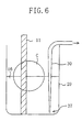
- the substrate 11 is put in a container 29 containing the liquid 16 used in method 1 so that the surface of the substrate 11 is substantially vertical to the level of the liquid 16 .
- the liquid 16 is then gradually drawn out at a constant rate from the container 29 via a tube 30 or the like.
- a hole may be formed in the lower portion of the container 29 to gradually draw out the liquid 16 at a constant rate.
- a wet film is formed on both surfaces of the substrate 11 .
- This wet film includes the complex particles 15 dispersed two-dimensionally, as the wet film shown in FIG. 2 . Therefore, once the wet film is dried, obtained is the substrate 11 with two-dimensional crystal of the complex particles 15 attaching thereto.
- Protein molecules are normally susceptible to heat and thus can be removed by applying heat.
- the protein molecules 14 of the complex particles 15 are therefore removed by heat treatment.
- the protein molecules 14 , and the polypeptide film 17 if method 1 was adopted are consumed by being left to stand in an atmosphere of inert gas such as nitrogen at 400 to 500°C for about one hour.
- the gold particles 12 are left behind on the substrate 11 in the shape of dots arranged regularly at high density with high precision.
- the gold particles 12 that had been held inside the complex particles 15 are uncovered in the state of a two-dimensional array on the substrate 11 arranged at high density with high precision.
- the nucleotide detector 10 of this embodiment is constructed of thiol DNAs 13 bonded to the gold particles 12 that are placed on the substrate 11 in the manner described above.
- the gold particles 12 and the thiol DNAs 13 can be bonded together by putting the substrate 11 with the gold particles 12 placed thereon in contact with an aqueous solution of the thiol DNAs 13 and leaving to stand for a predetermined period of time.
- the reason is that since sulfur easily reacts with gold, the sulfur at the end of the thiol DNA or RNA easily conjugates with the gold particle 12 .
- the sulfur atom S of the thiol DNA 13 and the gold particle 12 establish one-to-one conjugation as shown in FIG. 2(c) .
- the thiol DNAs 13 are placed on the substrate 11 at significantly high density with significantly high precision.
- the gold particles 12 are arranged two-dimensionally on the substrate 11 at high density with high precision, the resultant nucleotide detector 10 has the thiol DNAs 13 bonded to the gold particles 12 arranged two-dimensionally on the substrate 11 at high density with high precision, and also has particles placed with a uniform number of particles per unit area determined depending on the size of the particles.
- nucleotides such as thiol RNAs and PCR primers with thiol ends may be used in place of the thiol DNAs 13 .
- the concentration of the thiol DNAs 13 in the aqueous solution may be determined, theoretically, so that the number of the thiol DNAs 13 matches with the number of the gold particles 12 on the substrate 11 . Actually, however, it is preferable to set the number of the thiol DNAs 13 greater than the number of the gold particles 12 . Therefore, in this embodiment, a high-concentration aqueous solution of thiol DNAs is prepared to ensure that the solution contains the thiol DNAs 13 greater in number than the complex particles 15 contained in the complex-dispersed liquid 16 .
- the aqueous solution of the thiol DNAs 13 is preferably warmed to about 20 to 60°C.
- the nucleotide detector 10 of this embodiment capable of easily detecting DNA or RNA of which detection is desired is attained.
- a solution containing a group of DNAs for detection (subject DNA group) is prepared.
- the DNAs in the subject DNA group are labeled with fluorescence in advance.
- the solution of the fluorescence-labeled subject DNA group is put in contact with the nucleotide detector 10 with the thiol DNAs placed thereon and left to stand in this state.
- the thiol DNA of the nucleotide detector 10 and the DNA in question in the subject DNA group constitute a double helix, establishing stable bonding.
- the resultant nucleotide detector 10 is washed with a solution such as water containing no fluorescent substance, to remove the remaining DNAs in the subject DNA group that have not bonded to the thiol DNAs of the nucleotide detector, together with a slight amount of the fluorescent substance left behind on the nucleotide detector 10 .
- the surface of the nucleotide detector 10 is irradiated with light such as laser light to observe fluorescence. During this observation, fluorescence is emitted if the subject DNA group includes a DNA having a sequence that hybridizes with the thiol DNA of the nucleotide detector 10 .
- the nucleotide detector 10 of this embodiment has thiol DNAs placed in uniform over the substrate at high density with high precision. Therefore, this nucleotide detector can be used as a high-performance DNA sensor that provides fluorescence at high intensity in uniform with high precision and is significantly high in SN ratio. Therefore, by using the nucleotide detector 10 of this embodiment as the DNA sensor, it is possible to determine that a DNA having a predetermined sequence exists in the subject DNA group if the detected fluorescence intensity is higher than a predetermined value. In other words, it is possible to substantially eliminate the possibility of erroneous determination on whether or not a DNA having a predetermined sequence exists.
- the nucleotide detector 10 of this embodiment has thiol DNAs placed in uniform over the substrate at high density with high precision. Therefore, the fluorescence intensity exhibited after hybridization of a DNA having a predetermined sequence hardly differs among substrates. This eliminates the necessity of changing the setting of the threshold value of the fluorescence intensity for each substrate for determination on whether or not a hybridized DNA exists, and thus produces a remarkable effect of widely reducing the trouble for adjusting the fluorescence detector.
- the nucleotide detector 10 was used as the DNA sensor.
- the nucleotide detector 10 may be used as a RNA sensor by using an RNA group as the subject for detection, in place of the DNA group.
- the gold particles 12 and the thiol DNAs 13 were used.
- a combination of particles of other metal and DNAs treated to permit bonding to the metal particles may be used, in place of the combination of the gold particles 12 and the thiol DNAs 13 .
- nucleotide detectors such as DNA chips are not reusable.
- DNAs or RNAs
- the nucleotide detector of this embodiment can be reused by dissociating the hybridized DNA from the thiol DNA and washing it away.
- a nucleotide detector capable of detecting many types of DNAs is manufactured by a technique as shown in FIG. 7 , for example.
- a resin resist film 31 that can be denatured with light and removed with a developer is formed on the substrate.
- a mask 33 having an opening 32 is formed on the resin resist film 31 , and the resultant substrate is irradiated with light ⁇ incident from above the mask 33 . This denatures a portion 31' of the resin resist film 31 located in the opening 32 .
- the resultant substrate is treated with a developer to remove the denatured portion 31' of the resin resist film 31 and thus expose the corresponding gold particles 12 on the substrate 11 .
- the resultant substrate is then treated with the aqueous solution of the thiol DNAs in a manner as described with reference to FIGS. 2(b) and 2(c) .
- the thiol DNAs 13 are bonded to only the gold particles in the exposed portion.
- the type of the thiol DNAs 13 (in base sequence or the like) to be bonded to the exposed gold particles 12 is changed one after another, and the above operation is repeated for each type, to finally produce a nucleotide detector including DNAs bonded to the substrate in which the sequences of the DNAs are different among sections of the substrate.
- nucleotide detector of this embodiment By use of the nucleotide detector of this embodiment, it is possible to detect a plurality of different DNAs simultaneously. Detection using the nucleotide detector of this embodiment is performed in the following manner.
- a solution of a subject DNA group labeled with fluorescence in advance is put in contact with the nucleotide detector of this embodiment and left to stand in this state.
- the thiol DNA of the nucleotide detector and the DNA in question in the subject DNA group constitute a double helix, providing stable bonding.
- the resultant nucleotide detector is washed with water or the like, and irradiated with light to observe fluorescence. During this observation, fluorescence is emitted if a DNA in the subject DNA group has bonded to the thiol DNA of the nucleotide detector of this embodiment. By specifying the position from which fluorescence is emitted, the sequence of the hybridized DNA can be detected.
- the nucleotide detector of this embodiment also has thiol DNAs placed in uniform over the entire substrate at high density with high precision. Therefore, this nucleotide detector can be used as a high-performance DNA sensor that provides fluorescence at high intensity in uniform with high precision and is high in SN ratio.
- the thiol DNAs having different sequences among sections are fixed to the substrate by a uniform amount for each section. Therefore, the nucleotide detector of this embodiment can overcome the problem of the conventional DNA sensor that it is difficult to determine whether or not a DNA having a predetermined sequence exists in a section with low fluorescence intensity.
- the fluorescence intensity hardly differs among substrates. This eliminates the necessity of changing the setting of the threshold value of the fluorescence intensity for each substrate for determination on whether or not a hybridized DNA exists, and thus produces a remarkable effect of widely reducing the trouble for adjusting the fluorescence detector.
- the operations 1) to 3) above are repeated changing the type of the thiol DNAs 13 (in base sequence or the like) one after another and also changing the electrode 34' to which the positive potential is applied. In this way, a nucleotide detector including many thiol DNAs having different sequences bonded to one substrate 11 (multi-type DNA sensor) can be manufactured.
- the nucleotide detector of this embodiment can be used as a high-performance multi-type DNA sensor as in Embodiment 2.
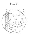
- FIG. 9 is an enlarged view of the circled portion C in FIG. 6 .
- the container 29 containing the liquid 16 is prepared.
- the liquid 16 is a mixture of a phosphoric acid buffer solution, pH 5.3, having a concentration of 40 mM and a sodium chloride aqueous solution having a concentration of 40 mM in equal proportions, with the complex particles 15 dispersed therein.
- the substrate 11 is then prepared, and, as shown in FIG. 6 , put in the container 29 so that the surface of the substrate 11 stands vertical to the level of the liquid 16 .
- the level of the liquid 16 is then lowered or raised. In Embodiment 1 above, the liquid level was lowered. This process of lowering the level of the liquid 16 will be described in detail.
- the liquid level slightly rises along the substrate 11 at the interface between the liquid 16 containing the complex particles 15 and the substrate 11 as shown in FIG. 9 , forming a meniscus portion M .
- a dispersion medium water in this embodiment
- the complex particles 15 exist in a significantly high concentration in the meniscus portion M of the liquid 16 and thus are arranged on the surface of the substrate 11 at high density with high precision.
- a wet film 35 including the complex particles 15 arranged at high density with high precision is formed on the surface of the substrate 11 .
- the meniscus portion M is also formed when the level of the liquid 16 is raised, and a wet film 35 including the complex particles 15 arranged at high density with high precision is formed on the surface of the substrate 11 .
- the complex particles 15 can be arranged at higher density with higher precision. It is therefore desirable to control the humidity at and around the liquid level so that the evaporation rate of the dispersion medium is low.
- the process in this embodiment may be performed in a closed system, and an air conditioner or the like may be provided to control the humidity inside the closed system so that the dispersion medium can be gradually evaporated.
- any vibration should desirably be eliminated to prevent the liquid level from being influenced by the vibration.
- the method in this embodiment may be performed on a vibration isolation base.
- the wet film 35 is formed on both surfaces of the substrate 11 .
- the wet film 35 includes the complex particles 15 arranged two-dimensionally at high density with high precision, it is not completely free from the dispersion medium.
- the wet film 35 is therefore completely dried to obtain the substrate 11 with two-dimensional crystal of the complex particles 15 formed thereon.
- FIG. 10 is a photomicrograph of a two-dimensional crystal film of the complex particles 15 formed on the surfaces of the substrate 11 of this embodiment. In this method, the complex particles 15 are crystallized while being aligned in parallel with the liquid level.
- the arrangement orientation is such that the direction vertical to the start line of the growth of the two-dimensional crystal film, that is, the growth direction is in the ⁇ 1-100> direction. This indicates that the complex particles 15 can be arranged regularly at high density with high precision.
- the number of the complex particles 15 placed on the surface of the substrate 11 can be easily calculated. In other words, the number of the complex particles 15 placed on the surface of the substrate 11 can be easily controlled by changing the area of the substrate 11 .
- the level of the liquid 16 can be gradually lowered by forming a hole through the bottom of the container 29 to allow the liquid to drip through this hole, for example.
- the level of the liquid 16 may be raised by gradually increasing the liquid 16 in the container 29 utilizing siphonage, for example.
- the liquid level lowering or raising rate is preferably kept constant.
- the liquid level lowering or raising rate is preferably lower to ensure formation of a good film of the complex particles on the substrate 11 .
- the liquid level lowering or raising rate for the liquid 16 is preferably 10 mm/min. or less. No specific lower limit is defined, but to achieve good economy industrially, it is appropriate to set the liquid level lowering or raising rate at about 0.1 mm/min.
- the liquid level lowering or raising rate is preferably about 0.1 to about 1 mm/min., more preferably about 0.12 to about 0.24 mm/min.
- the liquid 16 may be drawn out by sucking the liquid 16 from above the container 29 via a tube having one open end positioned inside the container 29 near the bottom thereof and the other open end coupled to a suction means located outside the container 29 , or by allowing the liquid to drop by gravity via a hole formed through the bottom of the container 29 .
- a tube 30 may be used as shown in FIG. 6 .
- One open end 37 of the tube 30 is positioned inside the container 29 near the bottom thereof and the other open end is coupled to a suction means (a syringe, an aspirator, a suction pump, or the like) located outside the container 29 .
- a suction means a syringe, an aspirator, a suction pump, or the like.
- the open end 37 of the tube 30 positioned near the bottom of the container 29 is not specifically restricted in shape and structure.
- the open end may be a circular shape or an obliquely cut shape.
- a rectangular parallelepiped structure of which the bottom is open may be attached to the open end (see FIG. 11(a) ) or the open end may have a funnel-shaped structure widened downwardly of which the bottom is open (see FIG. 11(b) )
- the tube 30 is preferably positioned so that the bottom of the rectangular parallelepiped structure or the funnel-shaped structure is in parallel with the bottom of the container 29 .
- the substrate 11 is preferably placed at a position sufficiently apart from the open end of the tube positioned near the bottom of the container 29 (the opening of the rectangular parallelepiped structure or the funnel-shaped structure if such a structure is provided at the end of the tube), that is, at a position free from influence of disturbance of the flow of the liquid 16 caused by suction of the liquid 16 .
- the liquid 16 may be drawn out by dropping the liquid via a hole formed through the bottom of the container 29 by gravity, in place of sucking from above the container 29 .
- the liquid 16 is drawn out from the bottom of the container 29 .
- the hole 38 may have a circular shape, or a triangular or other polygonal shape (hereinafter, collectively called a polygonal shape). It may also be a slit. Such a slit-shaped hole 38 may be long or short.
- the plurality of holes 38 are preferably arranged in a line as shown in FIGS. 12(a) and 12(b) , or they may be arranged in parallel lines as shown in FIGS. 12(c) and 12(d) . In the case of forming a plurality of long slit-shaped holes 38 through the bottom of the container 29 , they may be arranged in parallel with each other as shown in FIG. 12(f) .
- the plurality of holes 38 formed through the bottom of the container 29 are preferably lined in parallel with the surface of the substrate 11 .
- the substrate 11 is preferably placed so that the surface of the substrate 11 is positioned in parallel with the plurality of holes 38 formed through the bottom of the container 29 .
- the substrate 11 is preferably placed at a position sufficiently apart from the portion where the holes are formed, that is, at a position free from influence of disturbance of the flow of the liquid 16 caused by the drawing of the liquid 16 .
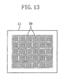
- the substrate 11 may have protrusions 39 on the surface thereof.
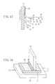
- FIGS. 14(a) to 14(c) by forming the protrusions 39 on the surface of the substrate 11 , a larger amount of the liquid 16 is left behind on a portion 40 surrounding each protrusion 39 by the surface tension of the liquid 16 . Therefore, a comparatively large number of complex particles 15 tend to gather on the surrounding portion 40 . As a result, a multilayer film of complex particles 15 can be selectively formed on the portion 40 surrounding the protrusion 39 . In short, by forming the protrusions 39 on the surface of the substrate 11 , it is possible to form a film of complex particles 15 arranged at higher density with higher precision.
- the complex particles 15 are ferritin particles containing particles of an inorganic material such as iron inside, and the substrate 11 is a semiconductor substrate, for example, a ferritin film is formed on the semiconductor substrate.
- a ferritin film is formed on the semiconductor substrate.
- protrusions 39 are not restricted to that shown in FIG. 13 . Only one protrusion may be formed on the surface of the substrate 11 , or a plurality of protrusions may be formed at random. Alternatively, a plurality of protrusions 39 may be placed regularly in a pattern other than the matrix pattern shown in FIG. 13 .
- the liquid 16 (a mixture of a phosphoric acid buffer solution, pH 5.3, having a concentration of 40 mM and a sodium chloride aqueous solution having a concentration of 40 mM in equal proportions, with the complex particles 15 dispersed therein) was used.
- This method is not restricted to this.
- this method is greatly usable for production of a particulate film using particulates other than the complex particles 15 ..
- particles of inorganic materials and organic materials having a diameter of 50 nm or less are usable as the particulates in this method.
- the organic materials include synthetic polymers and proteins.
- the proteins include (1) virus proteins forming capsids or envelopes of viruses (for example, adenovirus, rotavirus, poliovirus, HK97, CCMV, and the like), (2) proteins belonging to the ferritin family such as ferritin and apoferritin, and (3) Dps proteins and MrgA proteins (refer to the protein data banks).
- particles of the ferritin family such as ferritin and apoferritin having a diameter of 10 to 12 nm, or viruses, Dps proteins (protein particles one size smaller than ferritin particles having a diameter of about 9 nm and a core diameter of about 4 nm), and MrgA proteins having a diameter of 9 nm or less.
- protein particles obtained by translating DNAs or RNAs having the same base sequence It is preferable to use protein particles obtained by translating DNAs or RNAs having the same base sequence.
- a plurality of protein particles obtained by translating the same DNA or RNA have completely the same structure and are not likely to have diameters varying every molecule.
- protein particles have the self-assembling ability where they can construct a high-order structure together by recognizing one another. The protein particles having this ability can be arranged at high density with high precision.
- the concentration of the protein particles in the suspension is excessively low, the protein particles can exert only insufficient self-assembling function, failing to provide a good particulate film (two-dimensional crystal film).
- the concentration is excessively high, the self-assembling function saturates. This is not only uneconomical, but also may possibly lead to layered arrangement of protein particles, resulting in formation of a locally three-dimensional crystal film and thus failing to provide a film that can be effectively used industrially.
- the protein concentration is in the range of 10 ⁇ g/ml to 500 mg/ml, preferably in the range of 10 ⁇ g/ml to 200 mg/ml, more preferably in the range of 0.5 mg/ml to 100 mg/ml.
- the protein suspension may contain only protein in a dispersion medium (generally, pure water), or may additionally contain an electrolytic substance.
- the suspension containing only protein in pure water may generate large electrostatic repulsion between the substrate 11 and the protein particles, and this may cause slow adsorption of the protein particles to the substrate 11 .
- an electrolytic substance is added in this method.
- the electrolytic substance include sodium chloride, potassium chloride, calcium chloride, and magnesium chloride. If the content of the electrolytic substance is excessively large, the electrolytic substance is precipitated. In view of this, the content is suitably 300 mM or less, preferably about 150 mM (this is roughly the concentration of a normal saline solution), more preferably about 50 mM, in the case of sodium chloride.
- the protein suspension may be heated to accelerate the formation of the particulate film made of the protein particles.
- convection is generated in the protein suspension. This may adversely affect the array of the protein particles and thus block the formation of the film of particulates arranged beautifully at high density with high precision. Therefore, when the protein suspension is heated to accelerate the formation of the particulate film, it is desirable to heat the suspension, the substrate, and all of the other components in uniform so that the particulate film can be formed in the equilibrium state blocking generation of convection of the protein suspension.
- the surface of the substrate 11 may be subjected to hydrophilic treatment to charge the surface.
- hydrophilic treatment of the surface of the substrate 11 include active ozone treatment under ultraviolet irradiation at high temperature (about 110°C ), oxygen plasma treatment, and amino silane treatment.
- the pH of the protein suspension may be adjusted to fall within the range in which the charge of the substrate 11 immersed in the protein suspension is the opposite to the charge of the protein particles adsorbed to the surface of the substrate 11 .
- the charge of the substrate subjected to amino silane hydrophilic treatment is plus when the pH is 11 or less, while the charge of the ferritin particles is minus when the pH is 5 or more. Therefore, if the pH of the ferritin suspension is adjusted to fall within the range of 5 to 11, it is possible to facilitate the adsorption of the ferritin particles to the substrate subjected to amino silane hydrophilic treatment (formation of the ferritin particle film on the substrate). In other words, the adsorption of the ferritin particles to the substrate subjected to amino silane hydrophilic treatment is facilitated by use of the attraction between the plus charge and the minus charge. Only specific regions of the substrate surface may be subjected to hydrophilic treatment to form the wet film 35 according to the pattern of the regions.
- the substrate 11 is not necessarily subjected to hydrophilic treatment as described above, but may preferably be subjected to hydrophobic treatment depending on the type of the liquid 16 . That is, depending on the type of the liquid 16 (or the dispersion medium), the wet film 35 can be formed only on a hydrophilic substrate surface or only on a hydrophobic substrate surface. For example, when a hydrophobic dispersion medium is used, the wet film 35 is formed only on a hydrophobic substrate surface, not a hydrophilic substrate surface. Exceptionally, in the case of protein, the substrate 11 is usable even when the surface thereof is hydrophobic in some cases. This is because protein is denatured on the surface of the substrate 11 and by this denaturation the surface of the substrate 11 becomes hydrophilic, to allow the wet film 35 to be formed on the hydrophilic surface.
- apoferritin particles containing gold particles inside were arranged two-dimensionally at high density with high precision as shown in FIG. 2(a) by method 5 described above.
- used was a liquid containing gold particle-containing apoferritin in a normal saline solution in a concentration of 50 mg/ml.
- the liquid was drawn out from a container containing the liquid with a syringe at a drawing rate (liquid level lowering rate) of 0.1 mm/min.
- the thus-produced substrate was heat-treated in a nitrogen gas atmosphere at 450°Cfor one hour, to remove the apoferritin as the protein moiety and thus attain a substrate with only gold particles placed thereon in the shape of dots two-dimensionally at high density with high precision.
- the resultant substrate was then put in contact with a thiol DNA aqueous solution, to attain a DNA sensor having one-to-one bonding of thiol DNAs to the gold particles.
- a thiol DNA aqueous solution used was an aqueous solution containing thiol DNAs in a concentration of 70 mg/ml warmed to 37°C. T4 phage DNAs were used as the DNAs and sulfur atoms were bonded to ends of the DNAs.
- the substrate was kept in contact with the thiol DNA aqueous solution for one hour.
- the DNA sensor used for the detection test for the T4 phase DNA was immersed in 100°C pure water for 10 minutes, and then the surface of the DNA sensor having the hybridized DNA was exposed to flow of 100°C pure water for 10 minutes.
- the resultant surface of the DNA sensor was measured for fluorescence and found to have the same fluorescence intensity as that of the background. From this result, it was confirmed that the hybridized DNA had dissociated from the thiol DNAs of the DNA sensor.
- RNA sensor was produced in the same manner as that described in Example 1, except that thiol RNAs (thiol RNAs produced using mRNAs obtained by transcription of T4 phages with sulfur atoms bonded to ends of the mRNAs) was used in place of the thiol DNA.
- thiol RNAs thiol RNAs produced using mRNAs obtained by transcription of T4 phages with sulfur atoms bonded to ends of the mRNAs
- RNA sensor Using the resultant RNA sensor, a detection test was performed for separately synthesized complementary RNA. As a result, high fluorescence intensity was exhibited stably, and thus detection was very easy.
- Example 1 gold particles were placed two-dimensionally on a silicon substrate.
- a resin resist film made of polymthyl methacrylate (PMMA) was then formed on the substrate, and a photomask having openings was formed on the resin resist film.
- PMMA polymthyl methacrylate
- the substrate was irradiated with light from above of the photomask, and then treated with a developer to pattern the resin resist film, to thereby expose part of the gold particles on the substrate.
- the above operation was repeated while the type of the thiol DNAs (in base sequence or the like) to be bonded to the exposed gold particles was changed one after another, to attain a multi-type DNA sensor with DNAs having a number of different sequences bonded to the substrate.
- As the thiol DNAs T4 phage DNAs were used, and sulfur atoms were bonded to ends of the DNAs. A solution containing such thiol DNAs in a concentration of 70 mg/ml and warmed to 37°C was used. The substrate was kept in contact with the thiol DNA solution for one hour.
- detection tests were performed using a plurality of types of DNAs having different base sequences derived from T4 phage and a plurality of types of DNAs having different base sequences derived from M13 phage.
- a multi-type RNA sensor was produced in the same manner as that described in Example 3, except that thiol RNAs having a number of different sequences (thiol RNAs produced using part of T4 phage base sequences with sulfur atoms bonded to ends of the sequences) were used in place of the thiol DNAs having a number of different sequences.
- the multi-type RNA sensor Using the resultant multi-type RNA sensor, detection tests were performed using a plurality of mRNA sequences derived from T4 phage and a plurality of mRNA sequences derived from M13 phage.
- the multi-type RNA sensor exhibited high fluorescence intensity stably in expected sections, compared with the conventional multi-type RNA sensor, in the detection test for the T4 phage-derived mRNAs, and thus detection was very easy.
- the detection test for the M13 phage-derived mRNAs only the background fluorescence intensity was detected, indicating that no hybridized mRNA existed.
- a metal mask having openings was placed on a surface of a silicon substrate, and chromium and gold thin films were deposited by sputtering to form electrodes on the surface of the silicon substrate.
- Gold particles were then placed as in Example 1 on the electrodes.
- a positive potential was applied to an electrode in a region in which DNAs having a specific sequence were to be placed, and a negative potential was applied to the other electrodes. While applying these potentials, the substrate was put in contact with a thiol DNA solution, to allow thiol DNAs to establish one-to-one bonding to gold particles on the electrode.
- the above operation was repeated while the type of the thiol DNAs (in base sequence or the like) was changed one after another and also the electrode to which the positive potential was applied was sequentially changed, to attain a multi-type DNA sensor with thiol DNAs having a number of different sequences bonded to the substrate.
- Example 3 Using the thus-produced multi-type DNA sensor, detection tests as described in Example 3 were conducted, and substantially the same results as those described in Example 3 were obtained.
- a multi-type RNA sensor was produced in the same manner as that described in Example 5, except that thiol RNAs having a number of different sequences (thiol RNAs produced using part of T4 phage base sequences with sulfur atoms bonded to ends of the sequences) were used in place of the thiol DNAs having a number of different sequences.
- Example 4 Using the thus-produced multi-type RNA sensor, detection tests as described in Example 4 were performed, and substantially the same results as those described in Example 4 were obtained.
- a ferritin suspension containing ferritin as particulates containing ferritin particles having a size of 12 nm derived from a horse spleen in a normal saline solution in a concentration of 100 mg/ml.
- the substrate prepared was a silicon substrate (with a surface subjected to hydrophilic treatment with oxygen plasma) having a size of 40 mm wide ⁇ 50 mm long ⁇ 500 ⁇ m thick.
- the silicon substrate was put in a container containing the ferritin suspension so as to stand vertical to the liquid level of the ferritin suspension.
- a tube (diameter: 1mm) was placed in the container so that one open end thereof was positioned near the bottom of the container inside the container and the other open end was coupled to a syringe.
- the ferritin suspension was gradually drawn out from above the container at a liquid level lowering rate of 0.12 mm/min.
- the tube was placed so that the open end positioned near the bottom of the container was 20 mm apart from the silicon substrate.
- a wet film was formed on both surfaces of the silicon substrate.
- a substrate on both surfaces of which a particulate film made of ferritin particles arranged two-dimensionally at high density with high precision was formed.
- a particulate film was produced in the same manner as that described in Example 7, except that a container (10 cm ⁇ 10 cm ⁇ 10 cm, capacity: 1 liter) having one circular hole (diameter: 2 mm) formed through the bottom was used, in place of the syringe, so that the ferritin suspension in the container was dropped through this hole by gravity.
- ferritin particles were arranged two-dimensionally on both surfaces of the silicon substrate at high density with high precision.
- a ferritin particle film was produced on both surfaces of the substrate 3 in the same manner as that described in Example 1, except that a plurality of protrusions (each protrusion has a lattice shape and part of the lattice has been circularly stamped) were formed on one surface of the silicon substrate (the size and surface treatment were the same as those in Example 1). This example will be described with reference to FIG. 14 .
- the wet film 36 is formed on the portion 40 surrounding the protrusion 39 on the surface of the silicon substrate 11 .
- the wet film 36 has a divergent drop-like shape widening downwardly toward the silicon substrate as shown in FIG. 14(b) .
- the ferritin particles of the wet film 36 gather toward the protrusion 39 as indicated by the arrows due to decrease in the amount of the dispersion medium of the wet film 36 and the micro-capillary effect. Therefore, the concentration of the ferritin particles increases along the gathering path toward the protrusion 39 .
- the particulate film produced in this example with ferritin particles arranged two-dimensionally at high density with high precision has a thickness that is largest at a position adjacent to the protrusion 39 and gradually decreases as the position is farther from the protrusion 39 .
- a particulate film was produced in the same manner as that described in Example 9, except that an apoferritin suspension with zinc oxide-containing apoferritin particles, in place of the ferritin particles, suspended therein was used.
- the particulate film was heat-treated in a nitrogen atmosphere at 450°C for two hours. As a result, the protein moiety was removed, and super-fine particles of zinc oxide were formed on the silicon substrate.
- the air containing a trace amount of mercaptan was sprayed to the resultant substrate. As a result, the amount of mercaptan in the air was reduced.
- the substrate was then irradiated with an electronic beam to measure fluorescence, and it was found that the fluorescence intensity was different between before and after the exposure to the air containing a trace amount of mercaptan. It was therefore confirmed that the substrate with the particulate film formed thereon in this example was effective as a microsensor.
- the method for producing a particulate film of the present invention it is possible to easily produce a two-dimensional crystal film made of particulates having a diameter of the order of nanometers arranged at high density and at desired positions with high precision.
- two-dimensional crystal films made of particulates can be easily mass-produced in the industrial scale.
- the nucleotide detector of the present invention is usable for devices utilizing complementarity of nucleotides, such as DNA sensors and RNA sensors.
- the method for producing a particulate film of the present invention is usable for fabrication of devices requiring super-fine patterns, in particular, for fabrication of diffraction gratings, nucleotide detectors, and super-fine electronic devices such as transistors and diodes.
Landscapes
- Chemical & Material Sciences (AREA)
- Organic Chemistry (AREA)
- Life Sciences & Earth Sciences (AREA)
- Health & Medical Sciences (AREA)
- Proteomics, Peptides & Aminoacids (AREA)
- Zoology (AREA)
- Engineering & Computer Science (AREA)
- Wood Science & Technology (AREA)
- Analytical Chemistry (AREA)
- Immunology (AREA)
- Bioinformatics & Cheminformatics (AREA)
- Molecular Biology (AREA)
- Biophysics (AREA)
- Biotechnology (AREA)
- Physics & Mathematics (AREA)
- Biochemistry (AREA)
- Microbiology (AREA)
- General Engineering & Computer Science (AREA)
- General Health & Medical Sciences (AREA)
- Genetics & Genomics (AREA)
- Apparatus Associated With Microorganisms And Enzymes (AREA)
- Measuring Or Testing Involving Enzymes Or Micro-Organisms (AREA)
- Investigating, Analyzing Materials By Fluorescence Or Luminescence (AREA)
- Physical Or Chemical Processes And Apparatus (AREA)
Abstract
Description
Claims (13)
- A nucleotide detector comprising:a substrate;metal particles placed regularly on the substrate; andone of a pair of nucleotide molecules capable of conjugating with each other, the one nucleotide molecule being bonded to each of the metal particles.
- A method for manufacturing a nucleotide detector comprising the steps of:(a) arranging complex particles each including a metal particle and a protein molecule holding the metal particle on a substrate;(b) removing the protein molecules; and(c) bonding one of a pair of nucleotide molecules capable of conjugating with each other to each of the metal particles left on the substrate in the step (b).
- The method for manufacturing a nucleotide detector of Claim 2, wherein the protein molecules are Dps protein or apoferritin.
- The method for manufacturing a nucleotide detector of Claim 2 or 3, wherein the nucleotide molecules comprise a plurality of types of nucleotide molecules having different base sequences.
- A method for producing a particulate film comprising the steps of:(a) placing a substrate in a container so that a surface of the substrate is vertical to the liquid level of a liquid containing particulates filled in the container; and(b) raising or lowering the liquid level of the liquid.
- The method for producing a particulate film of Claim 5, wherein the particulates have a diameter of 50 nm or less.
- The method for producing a particulate film of Claim 5 or 6, wherein the particulates are protein.
- The method for producing a particulate film of Claim 7, wherein the protein contains an inorganic material inside.
- The method for producing a particulate film of Claim 7 or 8, wherein the concentration of the protein in the liquid is 10 µg/ml to 500 mg/ml.
- The method for producing a particulate film of any of Claims 7 to 9, wherein the liquid contains an electrolyte.
- The method for producing a particulate film of any of Claims 7 or 10, wherein a liquid level raising or lowering rate of the liquid is substantially constant, and it is 10 mm/min. or less.
- The method for producing a particulate film of any of Claims 7 to 11, wherein the liquid is allowed to flow out by gravity.
- The method for producing a particulate film of any of Claims 7 to 12, wherein the substrate has a convex and concave pattern on a surface.
Applications Claiming Priority (5)
| Application Number | Priority Date | Filing Date | Title |
|---|---|---|---|
| JP2000073805 | 2000-03-16 | ||
| JP2000073805 | 2000-03-16 | ||
| JP2000086116 | 2000-03-27 | ||
| JP2000086116 | 2000-03-27 | ||
| PCT/JP2001/002083 WO2001068834A1 (en) | 2000-03-16 | 2001-03-15 | Nucleotide detector, process for producing the same and process for forming fine particle membrane |
Publications (2)
| Publication Number | Publication Date |
|---|---|
| EP1186659A1 true EP1186659A1 (en) | 2002-03-13 |
| EP1186659A4 EP1186659A4 (en) | 2002-07-17 |
Family
ID=26587665
Family Applications (1)
| Application Number | Title | Priority Date | Filing Date |
|---|---|---|---|
| EP01912416A Withdrawn EP1186659A4 (en) | 2000-03-16 | 2001-03-15 | NUCLEOTIDE DETECTOR, METHOD FOR PRODUCING THE SAME, AND METHOD FOR FORMING A MEMBRANE OF FINE PARTICLES |
Country Status (4)
| Country | Link |
|---|---|
| US (2) | US20030013096A1 (en) |
| EP (1) | EP1186659A4 (en) |
| AU (1) | AU4116401A (en) |
| WO (1) | WO2001068834A1 (en) |
Cited By (8)
| Publication number | Priority date | Publication date | Assignee | Title |
|---|---|---|---|---|
| US6713173B2 (en) | 1996-11-16 | 2004-03-30 | Nanomagnetics Limited | Magnetizable device |
| US6815063B1 (en) | 1996-11-16 | 2004-11-09 | Nanomagnetics, Ltd. | Magnetic fluid |
| US6896957B1 (en) | 1996-11-16 | 2005-05-24 | Nanomagnetics, Ltd. | Magnetizable device |
| WO2005025737A3 (en) * | 2003-09-16 | 2005-08-18 | Upper Austrian Res Gmbh | Molecule arrays and method for producing the same |
| US6986942B1 (en) | 1996-11-16 | 2006-01-17 | Nanomagnetics Limited | Microwave absorbing structure |
| EP1283909A4 (en) * | 2000-05-04 | 2006-06-07 | Univ Yale | HIGH DENSITY PROTEIN NETWORKS FOR SCREENING PROTEIN ACTIVITY |
| EP1958689A1 (en) * | 2007-02-13 | 2008-08-20 | Samsung Electronics Co., Ltd. | Microarray and method of producing the same |
| CN103033546A (en) * | 2012-12-25 | 2013-04-10 | 南京工业大学 | A kind of organic-inorganic hybrid material modified electrode and preparation method thereof |
Families Citing this family (13)
| Publication number | Priority date | Publication date | Assignee | Title |
|---|---|---|---|---|
| US7102656B2 (en) * | 2002-05-21 | 2006-09-05 | Northwestern University | Electrostatically driven lithography |
| EP1624306A4 (en) * | 2003-04-30 | 2008-12-24 | Chengdu Kuachang Medical Ind L | Apparatus including nanostructures used for separation or analysis, and the preparation and application thereof |
| WO2006052104A1 (en) * | 2004-11-12 | 2006-05-18 | Seoul National University Industry Foundation | Method for aligning or assembling nano-structure on solid surface |
| JP5092405B2 (en) * | 2006-01-12 | 2012-12-05 | 東レ株式会社 | Selective binding substance immobilization carrier |
| WO2007108480A1 (en) * | 2006-03-20 | 2007-09-27 | Japan Science And Technology Agency | Method for fixing metal nanoparticle |
| JP5001019B2 (en) * | 2007-02-02 | 2012-08-15 | 株式会社日立ハイテクノロジーズ | Biomolecule detection element, method for producing biomolecule detection element, and biomolecule detection method |
| PT103730A (en) * | 2007-05-04 | 2008-11-04 | Univ Nova De Lisboa | COLORIMETRIC METHOD AND DETECTION CASE OF SPECIFIC SEQUENCES OF NUCLEIC ACIDS THROUGH METANIC NANOPARTICLES FUNCTIONALIZED WITH MODIFIED OLIGONUCLEOTIDES |
| US7871571B2 (en) * | 2007-10-25 | 2011-01-18 | Parker John A | Biomolecule analyzing system |
| JP2009170280A (en) * | 2008-01-17 | 2009-07-30 | Sony Corp | Method for manufacturing cold cathode field emission device and method for manufacturing cold cathode field emission display |
| EP3540059A1 (en) | 2010-04-16 | 2019-09-18 | Nuevolution A/S | Bi-functional complexes and methods for making and using such complexes |
| WO2015009418A1 (en) | 2013-07-15 | 2015-01-22 | United Technologies Corporation | Turbine vanes with variable fillets |
| JPWO2018047771A1 (en) * | 2016-09-09 | 2019-08-15 | 国立大学法人大阪大学 | Nucleic acid detection element and nucleic acid detection method |
| CN114177964B (en) * | 2022-01-18 | 2023-01-31 | 军事科学院系统工程研究院卫勤保障技术研究所 | Preparation method and application of planar single-layer micro-droplet array |
Family Cites Families (19)
| Publication number | Priority date | Publication date | Assignee | Title |
|---|---|---|---|---|
| JPS62183882A (en) * | 1986-02-07 | 1987-08-12 | Fujitsu Ltd | Preparation of protein built-up film |
| JP2545363B2 (en) * | 1986-04-18 | 1996-10-16 | 富士通株式会社 | Method for forming resist layer on substrate |
| US4779562A (en) | 1986-03-19 | 1988-10-25 | Fujitsu Limited | Apparatus for depositing mono-molecular layer |
| DK0487615T3 (en) * | 1989-08-18 | 1994-03-14 | Monsanto Co | Ferritin analogs |
| US5232503A (en) * | 1991-10-07 | 1993-08-03 | San Jose Technology | Apparatus for evaporatively coating objects with a predetermined thickness profile |
| JP2915812B2 (en) | 1994-12-07 | 1999-07-05 | 科学技術振興事業団 | Transfer adhesion method of fine particle film |
| JP2912562B2 (en) | 1995-02-27 | 1999-06-28 | 科学技術振興事業団 | Submicron lithography method for fine particle film |
| US5959098A (en) | 1996-04-17 | 1999-09-28 | Affymetrix, Inc. | Substrate preparation process |
| JP3756213B2 (en) | 1995-02-27 | 2006-03-15 | 独立行政法人科学技術振興機構 | Fine particle film, method for forming the same, and apparatus therefor |
| DE69737598T2 (en) * | 1996-07-29 | 2007-12-27 | Nanosphere Inc., Skokie | NANOPARTICLES WITH OLIGONUCLEOTIDES ADDITED TO IT AND THEIR USES |
| JP3649588B2 (en) * | 1997-05-30 | 2005-05-18 | 松下電器産業株式会社 | Quantum dot manufacturing method |
| EP0881691B1 (en) * | 1997-05-30 | 2004-09-01 | Matsushita Electric Industrial Co., Ltd. | Quantum dot device |
| US6239255B1 (en) * | 1997-08-29 | 2001-05-29 | Clement E. Furlong | Versatile surface plasmon resonance biosensors |
| JP3829491B2 (en) | 1998-08-27 | 2006-10-04 | 株式会社日立製作所 | Probe tip, probe tip creation method, sample detection method, and sample detection device |
| EP1115888B1 (en) * | 1998-09-24 | 2008-03-12 | Indiana University Research and Technology Corporation | Water-soluble luminescent quantum dots and bioconjugates thereof |
| US5958701A (en) * | 1999-01-27 | 1999-09-28 | The United States Of America As Represented By The Secretary Of The Navy | Method for measuring intramolecular forces by atomic force |
| CA2270807A1 (en) * | 1999-05-03 | 2000-11-03 | Ibm Canada Limited-Ibm Canada Limitee | Closed chamber method and apparatus for the coating of liquid films |
| WO2001000876A1 (en) * | 1999-06-25 | 2001-01-04 | Mirkin Chad A | Nanoparticles having oligonucleotides attached thereto and uses therefor |
| JP4403618B2 (en) * | 1999-12-21 | 2010-01-27 | パナソニック株式会社 | Method for producing carbon nanotube |
-
2001
- 2001-03-15 WO PCT/JP2001/002083 patent/WO2001068834A1/en not_active Ceased
- 2001-03-15 AU AU41164/01A patent/AU4116401A/en not_active Abandoned
- 2001-03-15 EP EP01912416A patent/EP1186659A4/en not_active Withdrawn
- 2001-03-15 US US09/979,438 patent/US20030013096A1/en not_active Abandoned
-
2003
- 2003-07-28 US US10/628,840 patent/US7129047B2/en not_active Expired - Fee Related
Cited By (11)
| Publication number | Priority date | Publication date | Assignee | Title |
|---|---|---|---|---|
| US6713173B2 (en) | 1996-11-16 | 2004-03-30 | Nanomagnetics Limited | Magnetizable device |
| US6815063B1 (en) | 1996-11-16 | 2004-11-09 | Nanomagnetics, Ltd. | Magnetic fluid |
| US6896957B1 (en) | 1996-11-16 | 2005-05-24 | Nanomagnetics, Ltd. | Magnetizable device |
| US6986942B1 (en) | 1996-11-16 | 2006-01-17 | Nanomagnetics Limited | Microwave absorbing structure |
| EP1283909A4 (en) * | 2000-05-04 | 2006-06-07 | Univ Yale | HIGH DENSITY PROTEIN NETWORKS FOR SCREENING PROTEIN ACTIVITY |
| US8399383B2 (en) | 2000-05-04 | 2013-03-19 | Yale University | Protein chips for high throughput screening of protein activity |
| WO2005025737A3 (en) * | 2003-09-16 | 2005-08-18 | Upper Austrian Res Gmbh | Molecule arrays and method for producing the same |
| AT501110A1 (en) * | 2003-09-16 | 2006-06-15 | Upper Austrian Res Gmbh | ARRAYS TO BIND MOLECULES |
| EP1958689A1 (en) * | 2007-02-13 | 2008-08-20 | Samsung Electronics Co., Ltd. | Microarray and method of producing the same |
| CN103033546A (en) * | 2012-12-25 | 2013-04-10 | 南京工业大学 | A kind of organic-inorganic hybrid material modified electrode and preparation method thereof |
| CN103033546B (en) * | 2012-12-25 | 2014-10-29 | 南京工业大学 | A kind of organic-inorganic hybrid material modified electrode and preparation method thereof |
Also Published As
| Publication number | Publication date |
|---|---|
| WO2001068834B1 (en) | 2001-11-01 |
| EP1186659A4 (en) | 2002-07-17 |
| WO2001068834A1 (en) | 2001-09-20 |
| US20040018548A1 (en) | 2004-01-29 |
| US7129047B2 (en) | 2006-10-31 |
| US20030013096A1 (en) | 2003-01-16 |
| AU4116401A (en) | 2001-09-24 |
Similar Documents
| Publication | Publication Date | Title |
|---|---|---|
| US7129047B2 (en) | Method for manufacturing a nucleotide detector | |
| JP4433100B2 (en) | Electrostatic spraying of substance solutions in mass production of chips and libraries | |
| TWI427709B (en) | Nanofiber surfaces for use in enhanced surface area applications | |
| ES2649962T3 (en) | Matrices of microparticles and their preparation procedures | |
| US7670831B2 (en) | Conductive carbon nanotubes dotted with metal and method for fabricating a biosensor using the same | |
| US8940663B2 (en) | Nano-scale biosensors | |
| JP4822753B2 (en) | Cell component sorting chip, cell component analysis system, and cell component analysis method using them | |
| DE60003171T2 (en) | METHODS FOR MINIATURIZED CELL ARRANGEMENT AND CELL-BASED SCREENING DEVICE | |
| US20080176768A1 (en) | Hydrogel microarray with embedded metal nanoparticles | |
| US9394547B2 (en) | Method and apparatus for delivery of molecules to cells | |
| WO2008108004A1 (en) | Chip for sampling cell component, system for analyzing cell component and method of analyzing cell component using the same | |
| JP2003322653A (en) | Probe fixed support and probe fixed carrier | |
| JP2008525763A (en) | Three-dimensional nanostructured and microstructured support | |
| KR100991011B1 (en) | Biosensor comprising carbon nanotubes to which metal nanoparticles are immobilized and a manufacturing method thereof | |
| JP2001181842A (en) | carbon nanotube | |
| JP2002195997A (en) | Nucleic acid detection sensor | |
| JP5046210B2 (en) | Method for forming fine particles and method for inspecting biological material using the fine particles | |
| US20190136329A1 (en) | Methods of detecting tumor cells | |
| CN101852795A (en) | Substrate for biochip and method for producing same | |
| JP4398953B2 (en) | Nucleic acid detection sensor | |
| US20150203348A1 (en) | Fabrication of nanowire arrays | |
| EP4592379A1 (en) | Method for forming microdroplets | |
| US20230022519A1 (en) | Three-dimensional structure and method for manufacturing the same | |
| JP2005345243A (en) | Nucleic acid detecting substrate and nucleic acid detecting method using it | |
| JPWO2001068834A1 (en) | Nucleotide detection device, its manufacturing method, and method for producing fine particle film |
Legal Events
| Date | Code | Title | Description |
|---|---|---|---|
| PUAI | Public reference made under article 153(3) epc to a published international application that has entered the european phase |
Free format text: ORIGINAL CODE: 0009012 |
|
| 17P | Request for examination filed |
Effective date: 20011213 |
|
| AK | Designated contracting states |
Kind code of ref document: A1 Designated state(s): AT BE CH CY DE DK ES FI FR GB GR IE IT LI LU MC NL PT SE TR |
|
| AX | Request for extension of the european patent |
Free format text: AL;LT;LV;MK;RO;SI |
|
| A4 | Supplementary search report drawn up and despatched |
Effective date: 20020605 |
|
| AK | Designated contracting states |
Kind code of ref document: A4 Designated state(s): AT BE CH CY DE DK ES FI FR GB GR IE IT LI LU MC NL PT SE TR |
|
| RIC1 | Information provided on ipc code assigned before grant |
Free format text: 7C 12N 15/09 A, 7C 12M 1/00 B, 7B 05D 1/18 B, 7G 01N 33/543 B, 7B 01J 19/00 B |
|
| STAA | Information on the status of an ep patent application or granted ep patent |
Free format text: STATUS: THE APPLICATION HAS BEEN WITHDRAWN |
|
| 18W | Application withdrawn |
Effective date: 20040817 |