EP1186550A2 - Sealing implement - Google Patents
Sealing implement Download PDFInfo
- Publication number
- EP1186550A2 EP1186550A2 EP01307354A EP01307354A EP1186550A2 EP 1186550 A2 EP1186550 A2 EP 1186550A2 EP 01307354 A EP01307354 A EP 01307354A EP 01307354 A EP01307354 A EP 01307354A EP 1186550 A2 EP1186550 A2 EP 1186550A2
- Authority
- EP
- European Patent Office
- Prior art keywords
- socket
- unit
- connecting means
- side wall
- sealing
- Prior art date
- Legal status (The legal status is an assumption and is not a legal conclusion. Google has not performed a legal analysis and makes no representation as to the accuracy of the status listed.)
- Withdrawn
Links
Images


Classifications
-
- B—PERFORMING OPERATIONS; TRANSPORTING
- B65—CONVEYING; PACKING; STORING; HANDLING THIN OR FILAMENTARY MATERIAL
- B65C—LABELLING OR TAGGING MACHINES, APPARATUS, OR PROCESSES
- B65C9/00—Details of labelling machines or apparatus
- B65C9/26—Devices for applying labels
-
- G—PHYSICS
- G09—EDUCATION; CRYPTOGRAPHY; DISPLAY; ADVERTISING; SEALS
- G09F—DISPLAYING; ADVERTISING; SIGNS; LABELS OR NAME-PLATES; SEALS
- G09F3/00—Labels, tag tickets, or similar identification or indication means; Seals; Postage or like stamps
- G09F3/02—Forms or constructions
- G09F3/03—Forms or constructions of security seals
- G09F3/0305—Forms or constructions of security seals characterised by the type of seal used
- G09F3/037—Forms or constructions of security seals characterised by the type of seal used having tie-wrap sealing means
-
- B—PERFORMING OPERATIONS; TRANSPORTING
- B65—CONVEYING; PACKING; STORING; HANDLING THIN OR FILAMENTARY MATERIAL
- B65C—LABELLING OR TAGGING MACHINES, APPARATUS, OR PROCESSES
- B65C7/00—Affixing tags
- B65C7/003—Affixing tags using paddle-shaped plastic pins
- B65C7/005—Portable tools
-
- B—PERFORMING OPERATIONS; TRANSPORTING
- B65—CONVEYING; PACKING; STORING; HANDLING THIN OR FILAMENTARY MATERIAL
- B65D—CONTAINERS FOR STORAGE OR TRANSPORT OF ARTICLES OR MATERIALS, e.g. BAGS, BARRELS, BOTTLES, BOXES, CANS, CARTONS, CRATES, DRUMS, JARS, TANKS, HOPPERS, FORWARDING CONTAINERS; ACCESSORIES, CLOSURES, OR FITTINGS THEREFOR; PACKAGING ELEMENTS; PACKAGES
- B65D63/00—Flexible elongated elements, e.g. straps, for bundling or supporting articles
- B65D63/10—Non-metallic straps, tapes, or bands; Filamentary elements, e.g. strings, threads or wires; Joints between ends thereof
- B65D63/1018—Joints produced by application of integral securing members, e.g. buckles, wedges, tongue and slot, locking head and teeth or the like
- B65D63/1027—Joints produced by application of integral securing members, e.g. buckles, wedges, tongue and slot, locking head and teeth or the like the integral securing member being formed as a female and male locking member, e.g. locking head and locking teeth, or the like
- B65D63/1063—Joints produced by application of integral securing members, e.g. buckles, wedges, tongue and slot, locking head and teeth or the like the integral securing member being formed as a female and male locking member, e.g. locking head and locking teeth, or the like the female locking member being provided with at least one plastic barb
- B65D63/1081—Joints produced by application of integral securing members, e.g. buckles, wedges, tongue and slot, locking head and teeth or the like the integral securing member being formed as a female and male locking member, e.g. locking head and locking teeth, or the like the female locking member being provided with at least one plastic barb with barbs situated on opposite sides of, or concentrically in, the female locking member
-
- Y—GENERAL TAGGING OF NEW TECHNOLOGICAL DEVELOPMENTS; GENERAL TAGGING OF CROSS-SECTIONAL TECHNOLOGIES SPANNING OVER SEVERAL SECTIONS OF THE IPC; TECHNICAL SUBJECTS COVERED BY FORMER USPC CROSS-REFERENCE ART COLLECTIONS [XRACs] AND DIGESTS
- Y10—TECHNICAL SUBJECTS COVERED BY FORMER USPC
- Y10T—TECHNICAL SUBJECTS COVERED BY FORMER US CLASSIFICATION
- Y10T156/00—Adhesive bonding and miscellaneous chemical manufacture
- Y10T156/18—Surface bonding means and/or assembly means with handle or handgrip
-
- Y—GENERAL TAGGING OF NEW TECHNOLOGICAL DEVELOPMENTS; GENERAL TAGGING OF CROSS-SECTIONAL TECHNOLOGIES SPANNING OVER SEVERAL SECTIONS OF THE IPC; TECHNICAL SUBJECTS COVERED BY FORMER USPC CROSS-REFERENCE ART COLLECTIONS [XRACs] AND DIGESTS
- Y10—TECHNICAL SUBJECTS COVERED BY FORMER USPC
- Y10T—TECHNICAL SUBJECTS COVERED BY FORMER US CLASSIFICATION
- Y10T24/00—Buckles, buttons, clasps, etc.
- Y10T24/14—Bale and package ties, hose clamps
- Y10T24/1402—Packet holders
- Y10T24/141—Plastic bands
-
- Y—GENERAL TAGGING OF NEW TECHNOLOGICAL DEVELOPMENTS; GENERAL TAGGING OF CROSS-SECTIONAL TECHNOLOGIES SPANNING OVER SEVERAL SECTIONS OF THE IPC; TECHNICAL SUBJECTS COVERED BY FORMER USPC CROSS-REFERENCE ART COLLECTIONS [XRACs] AND DIGESTS
- Y10—TECHNICAL SUBJECTS COVERED BY FORMER USPC
- Y10T—TECHNICAL SUBJECTS COVERED BY FORMER US CLASSIFICATION
- Y10T24/00—Buckles, buttons, clasps, etc.
- Y10T24/14—Bale and package ties, hose clamps
- Y10T24/1498—Plastic band
-
- Y—GENERAL TAGGING OF NEW TECHNOLOGICAL DEVELOPMENTS; GENERAL TAGGING OF CROSS-SECTIONAL TECHNOLOGIES SPANNING OVER SEVERAL SECTIONS OF THE IPC; TECHNICAL SUBJECTS COVERED BY FORMER USPC CROSS-REFERENCE ART COLLECTIONS [XRACs] AND DIGESTS
- Y10—TECHNICAL SUBJECTS COVERED BY FORMER USPC
- Y10T—TECHNICAL SUBJECTS COVERED BY FORMER US CLASSIFICATION
- Y10T24/00—Buckles, buttons, clasps, etc.
- Y10T24/15—Bag fasteners
- Y10T24/153—Plastic band bag tie
Definitions
- the present invention relates to a sealing implement for attaching sealing tags such as brand labels, price tags, material description, instruction manual, etc. to clothes, shoes, bags, and other products, and more particularly to a sealing implement that can smoothly attach tags when it is set to a special-purpose tag attaching tool (gun) for attaching tags as specified above.
- sealing tags such as brand labels, price tags, material description, instruction manual, etc.
- sealing implements In general, various kinds of sealing implements have been used for banding together clothes, women's boots, sandals, shoes, etc. or for attaching brand labels, price tags, etc.
- the sealing implement comprises a filament section for forming a loop for attaching a tag, an insertion head part provided on one end of the filament part, and a socket part provided with an insertion hole for allowing the relevant inserting head part to pass, and provided on another end of the filament section.
- a plurality of sealing implements are temporarily fixed to two bars -arranged in parallel to one another in such a manner so as to enable the socket part to be easily removed.
- such sealing implement is produced by being integrally molded preferably with synthetic resin or the like, and in particular, the filament section is elongated so as to exhibit extremely strong resistance against pulling operation.
- a latching piece which is a hook mounted near the insertion hole, opens, and this causes the neck part of the insertion head part to be reversibly fixed in the socket part, and a loop-form label attaching condition is completed, and sealing is achieved.
- these sealing implements are loaded in a special-purpose tag attaching tool (gun), and it is used not only for banding together boots, sandals, and shoes but also primarily for fixing brand labels and tags that carry the instruction manual of a product on such goods by pulling the lever.
- gun special-purpose tag attaching tool
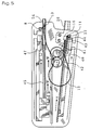
- FIG. 4 shows a perspective view of a configuration of one example of such conventional tag attaching tool (gun) 18 as shown in USP 5799375 or USP 5908110.
- an operating lever 18a as one example of an operating means.
- FIG. 4 is a perspective view showing the condition in which the sealing implement according to the present invention is set to the gun 18. A tag T is shown.
- vertical grooves 21, 22 are formed on the right and the left side of the gun for inserting the connecting bars 11, 11' of the sealing implement 10.
- the connecting bar 11 connecting the socket section 15 of the sealing implement 10 is inserted, and to the vertical groove 22, the connecting bar 11' connecting the inserting head section 13 is inserted.
- a shooting mechanism for shooting such sealing implement as shown in Fig. 5 is provided, in that at a side portion of the vertical groove 21, a first pushing means 40 for separating each one of the socket parts 15 of the sealing implement 1 from a connecting portion of the connecting bar 11 and for pushing forward each one of the separated socket parts 15 one by one along a curved socket guide 26.
- the first pushing means 40 comprises a flexible belt 41 having a rack portion and a gear portion 42 for sliding the flexible belt 41 back and forth by mating with the rack portion.
- a tip end portion 43 of the flexible belt 41 attaches to a surface 44 of the socket part 15 which is the surface to which the filament part 12 is contacted, and then the tip end portion 43 of the flexible belt 41 separatee the socket part 15 from the connecting part of the connecting bar 11. After that it transfers the socket part 15 to a front end portion of the curved socket guide 26.
- a second pushing means 45 which separates the insertion head part 13 of the sealing implement 1 from the connecting part of the connecting bar 11' and pushes each one of the insertion head parts 13 forward to the front end portion of the curved socket guide 26, one by one.
- the second pushing means 45 comprises a tubular guide 24 fixed to a main body of the gun 18 and a piston mechanism 47 having a gripping portion for gripping the insertion head part 13 at a tip portion thereof and which slides with response to an operation of the lever 18a.
- the piston portion 47 When the piston portion 47 is slid forward, it moves towards the curved socket guide 26 by gripping the insertion head part 13 of the sealing implement 1 arranged inside of the tubular guide 24 at a tip portion thereof and inserts the insertion head part 13 into the insertion hole 14 for receiving the insertion head part 13 of the socket part 15 which has already arrived at the front end portion of the curved socket guide 26.
- the gun in order to move each one of the sealing implements 1 forming the unit of sealing implement 10 thus mounted on the gun 18, to a position to be shot out, respectively, the gun is provided with a gear mechanism 50, 50' as shown in Fig. 9, which can mate with each connection portion formed between the insertion head part 13 or the socket part 15 and the connecting bar 11 or 11', respectively.
- each gear tooth of the gear portion of the gear mechanism 50, 50' can be rotated respectively, by utilizing a suitable cam mechanism or ratchet mechanism in response to the operation of the operating means 18a, it can be designed that the connecting bar can be moved downwardly by a length corresponding to a distance formed between the adjacently arranged sealing implements.
- a contacting surface 44 which is one of the side wall surfaces of the socket part 15 of the sealing implement 10 and at which a filament part 12 is contacted, is formed with a curved surface.
- the gun has not correctly operated. This causes the sealing implement to fail to shoot or causes a part of the sealing implement to be captured inside the gun, thereby causing extra operation by removing such captured part of the sealing implement and by resetting the sealing implement each time such problems occur.
- the present invention seeks to provide a sealing implement whose mounting operation for mounting the sealing implement on a gun has operational efficiency. It also seeks to provide a sealing implement which is able to constantly maintain the correct direction of a socket part so as to avoid an occurrence of jamming.
- the present invention basically adopts a configuration described as follows. That is, the present invention relates to a sealing implement comprising a flexible filament part, an insertion head part having an appropriate engaging part provided on one end part of the filament part, and a socket part having a hole for the purpose of irreversibly inserting the insertion head part, and provided on another end of the filament.
- a unit of sealing implements comprises a plurality of single sealing implements which are mutually and adjacently arranged substantially in parallel with each other and each plurality of insertion head parts or a portion in proximity thereto and each plurality of socket parts or a portion in proximity thereto are caused to be connected to separately provided connecting bars, respectively, and further wherein side wall surfaces of the socket parts, the surfaces being adjacently arranged to each other and oppositely disposed to each other, are connected to each other via a connecting means.
- the unit of sealing implements of the present invention has the technical concept that the socket parts of the sealing implement 1 are arranged in parallel with each other on the connecting bars and are spaced apart by a predetermined distance.
- the side wall surfaces of the socket parts are connected to each other by a suitable connecting means so that an arrangement configuration of each socket part cannot be deformed and is solidly kept at a predetermined position when each one of the sealing implements is shot out by the gun.
- the directions of an arrangement of the socket parts are generally not misaligned, and when the socket part 15 is separated from the connecting bar and is inserted into an entrance portion of the curved socket guide by the pushing means, there is generally little chance that the position of the socket part would be deformed with respect to an entrance portion of the curved socket guide, thereby reducing the occurrence of jamming.
- the operational efficiency of the shooting operation of the sealing implement may be improved.
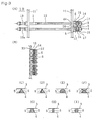
- FIG. 1 is a front view showing a configuration of one specific example of the sealing implement relating to the present invention and FIG. 2 is a side view thereof and Fig. 3 is a back side view thereof.
- a unit of sealing implements 10 comprising a plurality of single sealing implements 1 each of which comprises a flexible filament part 12, an insertion head part 13 having an appropriate engaging part 13a provided on one end part of the filament part 12 and a socket part 15 having a hole 14 for the purpose of irreversibly inserting the insertion head part 13, and provided on another end of the filament 12.
- a plurality of the single sealing implements 1 are mutually and adjacently arranged in parallel with each other and each of the plurality of insertion head parts 13 or a portion in proximity thereto and each of the plurality of socket parts 15 or a portion in proximity thereto are connected to separately provided connecting bars 11, 11', respectively.
- the sealing implement 10 according to the present invention is integrally molded generally with synthetic resin such as nylon, polypropylene, polyester, etc. as in the case of conventional sealing implements.
- FIG. 1 one specific example of the sealing implement 10 relating to the present invention is further described.
- the basic configuration of the sealing implement 10 relating to the present invention is nearly the same as that of the conventional sealing implement, and further at the socket section 15, an insertion hole 14 for irreversibly passing the inserting head section 13 is provided.
- the cross-sectional profile of the filament part 12 may be a circle, a flattened shape, or a rectangle.
- the socket section 15 is provided with an engaging section 17.
- Engaging section 17 is formed so as to project inside the insertion hole 14 from an inside surface thereof.
- Engaging section 17 is deformable and is adapted to engage with engaging section 13a which is formed on a part of the insertion head part 13 and which has a reduced diameter so as to form a stepwise configuration.
- one of the connecting bars 11 is connected to an end base portion or a portion in proximity thereto of the socket parts 15, each being arranged adjacently to each other. Additionally, a pair of the socket parts 15 which are adjacently arranged to each other are connected to each other with a suitable connecting means 5 so as to be mutually fixed.
- the side wall surfaces 3, 4 of a plurality of the socket parts 15, 15' are connected with each other by utilizing at least one connecting means 5.
- each socket part 15 is connected with the connecting bar 11 and the connecting means 5 in a lower portion and an upper portion thereof, the arrangement direction of the socket part can be prevented from being deformed even when it is shot from a gun.
- At least one connecting means 5 may be provided between a pair of side wall surfaces 3, 4 of the respective socket parts 15 of a unit of sealing implements 10.
- connecting means 5 are provided therebetween.
- one connecting means 5 is provided in the portion formed between a pair of the side wall surfaces 3, 4 of the respective socket parts 15, but it is preferred that two or three connecting means 5 are provided in the portions formed between a pair of the side wall surfaces 3, 4 of the respective socket parts 15.
- the connecting means 5 preferably has a fine configuration through out or a configuration having a portion which can attach to a side wall surface 3, 4 of the socket part 15 or attach to an opposite connecting means 5 via a pin point connection, so that it can be easily broken when a predetermined tensile strength or a predetermined shearing force is applied to the socket part 15.
- the connecting means 5 of the present invention has a suitable strength between the side wall surface 3 and 4 of the socket part 15 that enables the socket part 15 to be easily separated.
- socket parts 15 of the unit of sealing implements 10, each being adjacently arranged to each other are temporarily fixed to each other at a portion other than the connecting bar 11.
- the connecting means 5 of the present invention preferably comprises a thin and short connecting member 5' and this may be formed integrally with the socket part 15 when the socket part 15 is formed using a plastic molding method.
- the connecting member 5' forming the connecting means 5 has an uniform cross-sectional area in overall length thereof along a center axis thereof and thus it may a column or a rod having a polygonal cross-sectional configuration or the like,or it has a non-uniform cross-sectional area in overall length thereof along a center axis of the connecting member 5' as shown in Fig. 3(C) to Fig. 3(G) and Fig. 3(I).
- At least one end portion of the connecting member 5' forming the connecting means 5 may have a configuration selected from a group consisting of a circular cone type shape, a spherical shape, a semi-spherical shape, a pyramid type shape or the like as shown in Fig, 3(C) to Fig, 3(F).
- the configuration of the connecting member 5' may have a configuration which can contact the side wall surfaces 3, 4 of the socket part 15 via a pin-point connection or opposite connecting members 5' may be mutually connected to each other via a pin-point connection.
- one end of the connecting member 5' can be connected to the sidewall surface 3 or 4 of the socket part 15 via surface contact, the connecting portion of the connecting member 5' having a small cross-sectional area.
- a cross-sectional area of one end portion of the connecting member 5' of the connecting means 5,which portion contacts the side wall surface 3 of the side wall surfaces 3, 4 of a pair of the socket parts 15, is different from a cross-sectional area of another end portion of the connecting member 5' of the connecting means 5, which portion contacts the side wall surface 4 of the pair of socket parts.
- the cross-sectional area of one end portion of the connecting member 5' connected to the side wall surface is a cross-sectional area showing a connecting force that enables a pair of the socket parts 15 to be easily separated from each other when a certain external force is applied thereto.
- the connecting means 5 of the present invention may be formed by projecting the respective connecting members 5', 5' from each one of the side wall surfaces 3 and 4 of the socket parts 15 being adjacently arranged to each other, respectively : both of the tip ends contact each other at the middle portion between both side wall surfaces 3 and 4, as shown in Fig. 3(F).
- a cross-sectional configuration of the connecting member of the connecting means is a configuration selected from a group consisting of a circular type configuration, an ellipse type configuration, a rectangular type configuration, a flat type configuration, a semi-circular type configuration, a polygonal type configuration and a composite type configuration formed by combining at least two of aforementioned configurations to each other.
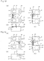
- the connecting means 5 can be formed at any portion of the side wall surface 3 or 4 of the socket part 15 but as a preferable embodiment of the present invention, as shown in Figs. 12 and 13, the connecting means 5 is provided at a position P on the side wall surface 3 or 4 of the socket part 15. Position P is located at a position communicating with or in proximity to a top surface S of the socket part 15 to which the filament part 12 is contacted and on which an insertion hole 14 into which the insertion head part 13 is inserted is provided.
- the connecting member 5' may be provided at a position formed on a side wall surface 3, 4 of the socket part 15 and located so that the distance formed between the connecting member 5' and the connecting bar 11 is set as long as possible.
- the moment for suppressing the deformation of the socket part 15 will become maximum so that the most preferable position fixing effect for the socket part 15 may be obtained.
- the connecting member 5' can also be provided at a position formed on a side wall surface 3, 4 of the socket part 15 and located so that the distance formed between the connecting member 5' and the connecting bar 11 is set as short as possible.
- the surface of goods may be prevented from being scratched by a residual connecting member 5'.
- a plurality of the connecting means 5 can be provided between a pair of the side wall surfaces 3, 4 of the respective socket parts 15 adjacently arranged to each other and oppositely disposed to each other.
- an arranging direction of the major axis of the cross-sectional configuration of one connecting member 5' is different from an arranging direction of the major axis of the cross-sectional configuration of another connecting member 5'.
- the connecting member 5'-1 which is located at a position far from the connecting bar 11, has a flat type cross-sectional configuration with a width of, for example, 0.3 mm and a thickness of, for example, 0.15mm as shown in Fig. 12(A) and Fig. 12(B).
- a width direction thereof is set in a direction in parallel with the surface direction of the upper surface S of the socket part 15. Also, as shown in Fig. 12(C), between the side wall'surfaces 3 and 4 of the respective adjacently arranged socket parts 15, one end portion 60 of the connecting member 5' which is connected to the side wall surface 3 is formed to have a configuration where its cross-sectional area gradually narrows towards the tip end portion thereof.
- the major axis of the cross-sectional configuration of the connecting member 5'-1 forming the connecting means 5, which is located at a position far from the connecting bar 11, is set at a direction which is in parallel with the surface direction of the upper surface S of the socket part 15 or with the direction of a center axis of the filament part 12.
- the connecting member 5'-2 forming the connecting means 5, which is located at a position closer to the connecting bar 11, has a flat type cross-sectional configuration with a width of, for example, 0.3 mm and a thickness of, for example, 0.15mm as shown in Fig. 13(A) and Fig. 13(B). It is arranged so that a width direction thereof is set at a direction perpendicular to the surface direction of the upper surface S of the socket part 15. Also, as shown in Fig. 13(C), between the side wall surfaces 3 and 4 of the respective adjacently arranged socket parts 15, one end portion 60 of the connecting member 5' which is connected to the side wall surface 3 is formed to have a configuration where its cross-sectional area gradually narrows towards the tip end portion thereof.
- the major axis of the cross-sectional configuration of the connecting member 5'-2 forming the connecting means 5, which is located at a position closer to the connecting bar 11, is set at a direction which is perpendicular to the surface direction of the upper surface S of the socket part 15 or perpendicular to a direction of a center axis of the filament part 12.
- an arrangement for a plurality of the socket parts 15 being adjacently arranged to each other is constantly uniform within the whole of the unit 10, and each of the socket parts 15 is so fixed to each other so as not to be deformed easily.
- each one of the sealing implements 1 can be easily separated from the connecting bar and shot out one by one, by operating an operation lever 18a provided on the gun 18, so that a tag or a label can be attached to goods.
- the unit of sealing implement of the present invention is so configured that a direction of a major axis of the cross-sectional configuration of the connecting member of the connecting means provided at a position located relatively far from the connecting bar, is arranged so as to comply with a surface direction of an upper surface of the socket part, while a direction of a major axis of the cross-sectional configuration of the connecting member of the connecting means provided at a position located relatively close to the connecting bar, is arranged so as to comply with a direction perpendicular to the surface direction of the upper surface of the socket part.
- a connecting means 5 formed into a fine string configuration 13' can also be used,as shown in Fig. 10 (A) and Fig. 10(B).
- the filament section used in the sealing implement relating to the present invention may have any kind of cross sectional configuration selected from a group consisting of a circle type, a flattened shape type, an ellipse type, a rectangular type or the like.
- the size of the socket part is preferably visually small enough to enable easy handling.
- a socket part 15 connected to the connecting bar 11 inserted into the vertical groove 21 is separated from the connecting section 58 of the connecting bar 11 by the first pushing means 40 and pushed out one by one forward along the curved socket guide 26 without jamming.
- the direction of the socket part 15 is pushed out along the socket guide 26 is turned by an angle of 90° and fits with the inserting head part 13 pushed out by a pushing pin 47 of the second pushing means 45, at the front end of the socket guide 26, through the insertion hole 14.
- the socket guide 26 changes its longitudinal direction by about 90° with a cylindrical tube so that a rod serving as the pushing means 40 is able to advance inside thereof while being bent.
- the gun is configured such that the timing of the head end of the pushing rod 41 reaching the top end of the socket guide 26 coincides with the timing of the pushing pin 47 reaching the same top end of the socket guide 26.
- the sealing implement 1 is able to attach labels successively and continuously to products, etc.
- Position Q may be approximately a center portion of the side wall surface 3, 4 of the socket part 15 and facing to a side at which the filament part 12 is existing.
- Position Q may be approximately a center portion of the side wall surface 44 of said socket part.
- Position Q may be located on a portion of or in proximity to an area at which the upper surface S of the socket part 15 on which the insertion hole 14 is provided intersects with the side wall surface 44.
- the side wall surface 44 of the socket part 15, being the side at which the filament part 12 is existing, is flat and the surface direction of the side wall surface 44 is perpendicular to the direction of the center axis of the filament part 12.
- a surface area of a region R of the socket part 15, with which a tip portion of the pushing rod 41 makes contact can be substantially enlarged and thus the operational efficiency can be greatly improved.
- a plurality of the connecting means 5 are disposed at spaces formed between two socket parts being adjacently arranged to each other.
- the present invention adopts the configuration as described above, deformation of the arrangement configuration of the socket part 15 is prevented after the sealing implement has been mounted on the gun and when each one of the socket parts 15 is pushed out by a predetermined pushing means, one by one; no jamming condition generally occurs as a result of the push direction of the top end portion of the socket part 15 being changed.
- each one of the units of sealing implements is easily taken out from its stacked stocks thereof or from a container thereof.
Landscapes
- Engineering & Computer Science (AREA)
- Computer Security & Cryptography (AREA)
- Physics & Mathematics (AREA)
- General Physics & Mathematics (AREA)
- Theoretical Computer Science (AREA)
- Mechanical Engineering (AREA)
- Labeling Devices (AREA)
- Connector Housings Or Holding Contact Members (AREA)
- Sealing Devices (AREA)
- Toys (AREA)
- Coating Apparatus (AREA)
Abstract
Description
- The present invention relates to a sealing implement for attaching sealing tags such as brand labels, price tags, material description, instruction manual, etc. to clothes, shoes, bags, and other products, and more particularly to a sealing implement that can smoothly attach tags when it is set to a special-purpose tag attaching tool (gun) for attaching tags as specified above.
- In general, various kinds of sealing implements have been used for banding together clothes, women's boots, sandals, shoes, etc. or for attaching brand labels, price tags, etc.
- For example, the sealing implement comprises a filament section for forming a loop for attaching a tag, an insertion head part provided on one end of the filament part, and a socket part provided with an insertion hole for allowing the relevant inserting head part to pass, and provided on another end of the filament section. A plurality of sealing implements are temporarily fixed to two bars -arranged in parallel to one another in such a manner so as to enable the socket part to be easily removed.
- Further, such sealing implement is produced by being integrally molded preferably with synthetic resin or the like, and in particular, the filament section is elongated so as to exhibit extremely strong resistance against pulling operation. when the inserting head section penetrates the narrow part of the socket section, a latching piece, which is a hook mounted near the insertion hole, opens, and this causes the neck part of the insertion head part to be reversibly fixed in the socket part, and a loop-form label attaching condition is completed, and sealing is achieved.
- Conventionally, these sealing implements are loaded in a special-purpose tag attaching tool (gun), and it is used not only for banding together boots, sandals, and shoes but also primarily for fixing brand labels and tags that carry the instruction manual of a product on such goods by pulling the lever.
- On the other hand, in the past, many kinds of apparatus for using to shoot this sealing implement for attaching the same on goods or the like by forming the filament part thereof into a loop-like shape with a suitable tag or the like, had been used with different mechanisms from each other.
- On of such examples will be explained with reference to Fig. 4, hereunder.
- Note that, Fig. 4 shows a perspective view of a configuration of one example of such conventional tag attaching tool (gun) 18 as shown in USP 5799375 or USP 5908110.
- When it is used, a conventional unit of
sealing implements 10 as shown in Fig. 6, which is disclosed in USP 5908110, is mounted on anupper surface 30 of thisgun 18 by making a shape of the sealing implement into a U type configuration and then each one of thesealing implements 1 is separated from the connecting bar, respectively, by operating an operating lever 18a as one example of an operating means. Thereby theinsertion head part 13 and thesocket part 15 can be coupled to each other. - A further explanation of this
gun 18 is given hereunder. - FIG. 4 is a perspective view showing the condition in which the sealing implement according to the present invention is set to the
gun 18. A tag T is shown. - Referring to the
gun 18,vertical grooves bars 11, 11' of thesealing implement 10. To thevertical groove 21, for example, the connectingbar 11 connecting thesocket section 15 of thesealing implement 10 is inserted, and to thevertical groove 22, the connecting bar 11' connecting theinserting head section 13 is inserted. - In addition, on the
gun 18, a shooting mechanism for shooting such sealing implement as shown in Fig. 5 is provided, in that at a side portion of thevertical groove 21, a first pushing means 40 for separating each one of thesocket parts 15 of thesealing implement 1 from a connecting portion of the connectingbar 11 and for pushing forward each one of the separatedsocket parts 15 one by one along acurved socket guide 26. - The first pushing means 40 comprises a
flexible belt 41 having a rack portion and agear portion 42 for sliding theflexible belt 41 back and forth by mating with the rack portion. - Therefore, in the conventional embodiment, each time the lever 18a is operated, a
tip end portion 43 of theflexible belt 41 attaches to asurface 44 of thesocket part 15 which is the surface to which thefilament part 12 is contacted, and then thetip end portion 43 of theflexible belt 41 separatee thesocket part 15 from the connecting part of the connectingbar 11. After that it transfers thesocket part 15 to a front end portion of thecurved socket guide 26. - Furthermore, at a side portion of the
vertical groove 22 is provided a second pushing means 45 which separates theinsertion head part 13 of thesealing implement 1 from the connecting part of the connecting bar 11' and pushes each one of theinsertion head parts 13 forward to the front end portion of thecurved socket guide 26, one by one. - The second pushing means 45 comprises a
tubular guide 24 fixed to a main body of thegun 18 and apiston mechanism 47 having a gripping portion for gripping theinsertion head part 13 at a tip portion thereof and which slides with response to an operation of the lever 18a. - When the
piston portion 47 is slid forward, it moves towards thecurved socket guide 26 by gripping theinsertion head part 13 of thesealing implement 1 arranged inside of thetubular guide 24 at a tip portion thereof and inserts theinsertion head part 13 into theinsertion hole 14 for receiving theinsertion head part 13 of thesocket part 15 which has already arrived at the front end portion of thecurved socket guide 26. - Note that, in the conventional embodiment, in order to move each one of the
sealing implements 1 forming the unit of sealingimplement 10 thus mounted on thegun 18, to a position to be shot out, respectively, the gun is provided with agear mechanism 50, 50' as shown in Fig. 9, which can mate with each connection portion formed between theinsertion head part 13 or thesocket part 15 and the connectingbar 11 or 11', respectively. - Thus, by enabling each gear tooth of the gear portion of the
gear mechanism 50, 50' to be rotated respectively, by utilizing a suitable cam mechanism or ratchet mechanism in response to the operation of the operating means 18a, it can be designed that the connecting bar can be moved downwardly by a length corresponding to a distance formed between the adjacently arranged sealing implements. - However, in the conventional sealing implement 10 described above, as shown in Figs. 7(A) and Fig. 7(B), a contacting
surface 44, which is one of the side wall surfaces of thesocket part 15 of thesealing implement 10 and at which afilament part 12 is contacted, is formed with a curved surface. Thus, when thetip end portion 43 of theflexible belt 41, that has the function of pushing out thesocket part 15, is attached to theside wall surface 44, as shown in Fig. 8, the direction of thesocket part 15 is easily deformed from the originally arranged direction. Thus, the direction of the longitudinal axis of thesocket part 15 becomes different from the direction of the longitudinal axis of thefilament part 12, resulting in a head of thesocket part 15 not being smoothly inserted into thecurved socket guide 26. - Therefore, there have been many cases where the insertion operation for inserting the
insertion head part 13 into an entrance portion of thecurved socket guide 26 has been discontinued such that jamming has frequently occurred. - Further, during storage of a plurality of the units of
sealing implements 10, when some kind of load had been applied to thesocket part 15, the direction of arrangement for eachsocket part 15 has been deformed, as shown in Fig. 8. The same problem as mentioned above has then occurred, in that a front end of thesocket part 15 cannot be smoothly inserted into the entrance portion of thecurved socket guide 26 when the sealingimplement 1 is shot. - Accordingly, by using the conventional sealing implement and the conventional gun, it is apparent that the operation efficiency thereof has been greatly reduced due not only to an occurrence of malfunction of the mechanism but also to an occurrence of jamming. This results in stopping of operation as well as removal of the jammed portion.
- That is to say, in using the conventional sealing implement and the conventional gun, the gun has not correctly operated. This causes the sealing implement to fail to shoot or causes a part of the sealing implement to be captured inside the gun, thereby causing extra operation by removing such captured part of the sealing implement and by resetting the sealing implement each time such problems occur.
- Accordingly, the present invention seeks to provide a sealing implement whose mounting operation for mounting the sealing implement on a gun has operational efficiency. It also seeks to provide a sealing implement which is able to constantly maintain the correct direction of a socket part so as to avoid an occurrence of jamming.
- In order to solve the above problems, the present invention basically adopts a configuration described as follows. That is, the present invention relates to a sealing implement comprising a flexible filament part, an insertion head part having an appropriate engaging part provided on one end part of the filament part, and a socket part having a hole for the purpose of irreversibly inserting the insertion head part, and provided on another end of the filament. A unit of sealing implements comprises a plurality of single sealing implements which are mutually and adjacently arranged substantially in parallel with each other and each plurality of insertion head parts or a portion in proximity thereto and each plurality of socket parts or a portion in proximity thereto are caused to be connected to separately provided connecting bars, respectively, and further wherein side wall surfaces of the socket parts, the surfaces being adjacently arranged to each other and oppositely disposed to each other, are connected to each other via a connecting means.
- In order to resolve the above-mentioned problems, the unit of sealing implements of the present invention has the technical concept that the socket parts of the sealing
implement 1 are arranged in parallel with each other on the connecting bars and are spaced apart by a predetermined distance. The side wall surfaces of the socket parts, said surfaces being adjacently arranged to each other and facing each other, are connected to each other by a suitable connecting means so that an arrangement configuration of each socket part cannot be deformed and is solidly kept at a predetermined position when each one of the sealing implements is shot out by the gun. - Accordingly, in the present invention, even when an improper external force is applied to the unit of sealing implements during transportation or storage thereof, the directions of an arrangement of the socket parts are generally not misaligned, and when the
socket part 15 is separated from the connecting bar and is inserted into an entrance portion of the curved socket guide by the pushing means, there is generally little chance that the position of the socket part would be deformed with respect to an entrance portion of the curved socket guide, thereby reducing the occurrence of jamming. - Therefore, in the present invention, the operational efficiency of the shooting operation of the sealing implement may be improved.
- FIG. 1 is a front view showing the configuration of one specific example of the sealing implement relating to the present invention;
- FIG. 2 is a side view showing the configuration of one specific example of the sealing implement relating to the present invention;
- FIG. 3 (A) is a back side view showing the configuration of one specific example of the sealing implement relating to the present invention and FIG. 3 (B) shows various kinds of connecting means as used in the present invention while FIG. 3 (C) shows various kinds of side view of connecting means as used in the present invention;
- FIG. 4 is a perspective view showing the condition in which the sealing implement according to the present invention is mounted on a special-purpose tag attaching tool (gun);
- FIG. 5 is a planar view showing a sealing implement shooting mechanism of a gun as shown in Fig. 4;
- FIG. 6 is a plan view showing a part of one embodiment of a conventional sealing implement.
- FIG. 7(A) and FIG. 7(B) are enlarged side and planar views of a socket part of a conventional sealing implement, respectively;
- FIG. 8 (A) and FIG. 8 (B) are views explaining problems occurring in the conventional sealing implement;
- FIG. 9 is a side view showing a sealing implement transferring mechanism of a conventional gun;
- FIG. 10 are views showing another embodiment of the connecting means as used in the present invention;
- FIG. 11 is a view showing a separate embodiment of the connecting means as used in the present invention;
- FIGS. 12 and 13 are views showing further separate embodiments of the connecting means as used in the present invention;
- FIGS. 12(A) and 13(A) are plan views of a pair of socket parts; FIGS. 12(B) and 13(B) are views of one side of a socket part; and FIGS. 12(C) and 13(C) are views of another side of a pair of socket parts.
-
- Referring now to the drawings, a description will be made in detail of the configuration of one specific example of the sealing implement relating to the present invention.
- That is, FIG. 1 is a front view showing a configuration of one specific example of the sealing implement relating to the present invention and FIG. 2 is a side view thereof and Fig. 3 is a back side view thereof.
- Note that these Figs. disclose a unit of sealing
implements 10 comprising a plurality ofsingle sealing implements 1 each of which comprises aflexible filament part 12, aninsertion head part 13 having an appropriateengaging part 13a provided on one end part of thefilament part 12 and asocket part 15 having ahole 14 for the purpose of irreversibly inserting theinsertion head part 13, and provided on another end of thefilament 12.
A plurality of thesingle sealing implements 1 are mutually and adjacently arranged in parallel with each other and each of the plurality ofinsertion head parts 13 or a portion in proximity thereto and each of the plurality ofsocket parts 15 or a portion in proximity thereto are connected to separately provided connectingbars 11, 11', respectively. -
Side wall surfaces socket parts 15 being adjacently arranged to each other and oppositely disposed to each other, are connected to each other via aconnecting means 5. - The sealing implement 10 according to the present invention is integrally molded generally with synthetic resin such as nylon, polypropylene, polyester, etc. as in the case of conventional sealing implements.
- Referring now to FIG. 1, one specific example of the sealing implement 10 relating to the present invention is further described.
- First of all, the basic configuration of the sealing implement 10 relating to the present invention is nearly the same as that of the conventional sealing implement, and further at the
socket section 15, aninsertion hole 14 for irreversibly passing the insertinghead section 13 is provided. - In the present invention, the cross-sectional profile of the
filament part 12 may be a circle, a flattened shape, or a rectangle. - The
socket section 15 is provided with an engagingsection 17. Engagingsection 17 is formed so as to project inside theinsertion hole 14 from an inside surface thereof. Engagingsection 17 is deformable and is adapted to engage with engagingsection 13a which is formed on a part of theinsertion head part 13 and which has a reduced diameter so as to form a stepwise configuration. - In the present invention, as shown in Figs 1 to 3, one of the connecting
bars 11 is connected to an end base portion or a portion in proximity thereto of thesocket parts 15, each being arranged adjacently to each other. Additionally, a pair of thesocket parts 15 which are adjacently arranged to each other are connected to each other with a suitable connectingmeans 5 so as to be mutually fixed. - That is to say, in the present invention, the side wall surfaces 3, 4 of a plurality of the
socket parts 15, 15', each being adjacently arranged to each other and adjacently facing each other, are connected with each other by utilizing at least one connectingmeans 5. - Accordingly, in the present invention, since each
socket part 15 is connected with the connectingbar 11 and the connectingmeans 5 in a lower portion and an upper portion thereof, the arrangement direction of the socket part can be prevented from being deformed even when it is shot from a gun. - In the present invention, at least one connecting
means 5 may be provided between a pair of side wall surfaces 3, 4 of therespective socket parts 15 of a unit of sealing implements 10. - Preferably two or more connecting
means 5 are provided therebetween. - Note that, in the sealing implement 10 of the present invention, as shown in Fig. 1, one connecting
means 5 is provided in the portion formed between a pair of the side wall surfaces 3, 4 of therespective socket parts 15, but it is preferred that two or three connectingmeans 5 are provided in the portions formed between a pair of the side wall surfaces 3, 4 of therespective socket parts 15. - Additionally, in the present invention, as shown in Fig. 3(B), different numbers of connecting
means 5 are provided in the portion formed between the side wall surfaces 3, 4 of therespective socket parts 15 adjacently arranged to each other. - In the present invention, the connecting
means 5 preferably has a fine configuration through out or a configuration having a portion which can attach to aside wall surface socket part 15 or attach to an opposite connectingmeans 5 via a pin point connection, so that it can be easily broken when a predetermined tensile strength or a predetermined shearing force is applied to thesocket part 15. - In other words, the connecting
means 5 of the present invention has a suitable strength between theside wall surface socket part 15 that enables thesocket part 15 to be easily separated. - It should be understood that the
socket parts 15 of the unit of sealing implements 10, each being adjacently arranged to each other, are temporarily fixed to each other at a portion other than the connectingbar 11. - The connecting means 5 of the present invention, as shown in Fig. 3(C) to Fig. 3(I), preferably comprises a thin and short connecting member 5' and this may be formed integrally with the
socket part 15 when thesocket part 15 is formed using a plastic molding method. - As shown in Fig. 3(H), the connecting member 5' forming the connecting
means 5 has an uniform cross-sectional area in overall length thereof along a center axis thereof and thus it may a column or a rod having a polygonal cross-sectional configuration or the like,or it has a non-uniform cross-sectional area in overall length thereof along a center axis of the connecting member 5' as shown in Fig. 3(C) to Fig. 3(G) and Fig. 3(I). - For example, in the connecting
means 5 of the present invention, at least one end portion of the connecting member 5' forming the connectingmeans 5, may have a configuration selected from a group consisting of a circular cone type shape, a spherical shape, a semi-spherical shape, a pyramid type shape or the like as shown in Fig, 3(C) to Fig, 3(F). - Note that, the configuration of the connecting member 5' may have a configuration which can contact the side wall surfaces 3, 4 of the
socket part 15 via a pin-point connection or opposite connecting members 5' may be mutually connected to each other via a pin-point connection. - On the other hand, one end of the connecting member 5' can be connected to the
sidewall surface socket part 15 via surface contact, the connecting portion of the connecting member 5' having a small cross-sectional area. - That is to say, in the present invention, it is also preferable that a cross-sectional area of one end portion of the connecting member 5' of the connecting
means 5,which portion contacts theside wall surface 3 of the side wall surfaces 3, 4 of a pair of thesocket parts 15, is different from a cross-sectional area of another end portion of the connecting member 5' of the connectingmeans 5, which portion contacts theside wall surface 4 of the pair of socket parts. - The cross-sectional area of one end portion of the connecting member 5' connected to the side wall surface is a cross-sectional area showing a connecting force that enables a pair of the
socket parts 15 to be easily separated from each other when a certain external force is applied thereto. - The connecting means 5 of the present invention may be formed by projecting the respective connecting members 5', 5' from each one of the side wall surfaces 3 and 4 of the
socket parts 15 being adjacently arranged to each other, respectively : both of the tip ends contact each other at the middle portion between both side wall surfaces 3 and 4, as shown in Fig. 3(F). - In a further separate embodiment of the present invention, as shown in Fig. 3(B), some portions formed between two adjacently arranged
socket parts 15 are provided with no such connectingmeans 5 at a predetermined interval. - In the present invention, a cross-sectional configuration of the connecting member of the connecting means is a configuration selected from a group consisting of a circular type configuration, an ellipse type configuration, a rectangular type configuration, a flat type configuration, a semi-circular type configuration, a polygonal type configuration and a composite type configuration formed by combining at least two of aforementioned configurations to each other.
- On the other hand, in the sealing implement 1 of the present invention, the connecting
means 5 can be formed at any portion of theside wall surface socket part 15 but as a preferable embodiment of the present invention, as shown in Figs. 12 and 13, the connectingmeans 5 is provided at a position P on theside wall surface socket part 15. Position P is located at a position communicating with or in proximity to a top surface S of thesocket part 15 to which thefilament part 12 is contacted and on which aninsertion hole 14 into which theinsertion head part 13 is inserted is provided. - In the present invention, when only one of the connecting
means 5 is provided between side wall surfaces 3 and 4 of a pair ofsocket parts 15, it is preferable that the connecting member 5'may be provided at a position formed on aside wall surface socket part 15 and located so that the distance formed between the connecting member 5' and the connectingbar 11 is set as long as possible. - In this case, the moment for suppressing the deformation of the
socket part 15 will become maximum so that the most preferable position fixing effect for thesocket part 15 may be obtained. - On the other hand, in the present invention, the connecting member 5' can also be provided at a position formed on a
side wall surface socket part 15 and located so that the distance formed between the connecting member 5' and the connectingbar 11 is set as short as possible. - In this case, the surface of goods may be prevented from being scratched by a residual connecting member 5'.
- of course, in the present invention, a plurality of the connecting
means 5 can be provided between a pair of the side wall surfaces 3, 4 of therespective socket parts 15 adjacently arranged to each other and oppositely disposed to each other. - A further separate embodiment of the present invention will be explained hereunder.
- In the present invention, in a case where a plurality of connecting
means 5 are used and where each one of the connecting members 5' of the connectingmeans 5 having a cross-sectional configuration selected from a group consisting of an ellipse type configuration, a rectangular type configuration, a flat type configuration and a semi-circular type configuration, each having a major axis, an arranging direction of the major axis of the cross-sectional configuration of one connecting member 5' is different from an arranging direction of the major axis of the cross-sectional configuration of another connecting member 5'. - More specifically, in this embodiment, as shown in Figs. 12 and 13, the connecting member 5'-1, which is located at a position far from the connecting
bar 11, has a flat type cross-sectional configuration with a width of, for example, 0.3 mm and a thickness of, for example, 0.15mm as shown in Fig. 12(A) and Fig. 12(B). - It is arranged so that a width direction thereof is set in a direction in parallel with the surface direction of the upper surface S of the
socket part 15. Also, as shown in Fig. 12(C), between the side wall'surfaces 3 and 4 of the respective adjacently arrangedsocket parts 15, oneend portion 60 of the connecting member 5' which is connected to theside wall surface 3 is formed to have a configuration where its cross-sectional area gradually narrows towards the tip end portion thereof. - Note that, in this embodiment, the major axis of the cross-sectional configuration of the connecting member 5'-1 forming the connecting
means 5, which is located at a position far from the connectingbar 11, is set at a direction which is in parallel with the surface direction of the upper surface S of thesocket part 15 or with the direction of a center axis of thefilament part 12. - On the other hand, the connecting member 5'-2 forming the connecting
means 5, which is located at a position closer to the connectingbar 11, has a flat type cross-sectional configuration with a width of, for example, 0.3 mm and a thickness of, for example, 0.15mm as shown in Fig. 13(A) and Fig. 13(B). It is arranged so that a width direction thereof is set at a direction perpendicular to the surface direction of the upper surface S of thesocket part 15. Also, as shown in Fig. 13(C), between the side wall surfaces 3 and 4 of the respective adjacently arrangedsocket parts 15, oneend portion 60 of the connecting member 5' which is connected to theside wall surface 3 is formed to have a configuration where its cross-sectional area gradually narrows towards the tip end portion thereof. - Note that, in this embodiment, the major axis of the cross-sectional configuration of the connecting member 5'-2 forming the connecting
means 5, which is located at a position closer to the connectingbar 11, is set at a direction which is perpendicular to the surface direction of the upper surface S of thesocket part 15 or perpendicular to a direction of a center axis of thefilament part 12. - In the present invention, an arrangement for a plurality of the
socket parts 15 being adjacently arranged to each other is constantly uniform within the whole of theunit 10, and each of thesocket parts 15 is so fixed to each other so as not to be deformed easily. - Accordingly, in the present invention, each one of the sealing implements 1 can be easily separated from the connecting bar and shot out one by one, by operating an operation lever 18a provided on the
gun 18, so that a tag or a label can be attached to goods. - As mentioned above, the unit of sealing implement of the present invention, is so configured that a direction of a major axis of the cross-sectional configuration of the connecting member of the connecting means provided at a position located relatively far from the connecting bar, is arranged so as to comply with a surface direction of an upper surface of the socket part, while a direction of a major axis of the cross-sectional configuration of the connecting member of the connecting means provided at a position located relatively close to the connecting bar, is arranged so as to comply with a direction perpendicular to the surface direction of the upper surface of the socket part.
- Additionally, as a further different embodiment of the present invention, a connecting
means 5 formed into a fine string configuration 13' can also be used,as shown in Fig. 10 (A) and Fig. 10(B). - The filament section used in the sealing implement relating to the present invention may have any kind of cross sectional configuration selected from a group consisting of a circle type, a flattened shape type, an ellipse type, a rectangular type or the like. In addition, the size of the socket part is preferably visually small enough to enable easy handling.
- On the other hand, in the present invention, as shown in Fig. 4, a
socket part 15 connected to the connectingbar 11 inserted into thevertical groove 21, is separated from the connectingsection 58 of the connectingbar 11 by the first pushingmeans 40 and pushed out one by one forward along thecurved socket guide 26 without jamming. - By doing this, the direction of the
socket part 15 is pushed out along thesocket guide 26 is turned by an angle of 90° and fits with the insertinghead part 13 pushed out by a pushingpin 47 of the second pushingmeans 45, at the front end of thesocket guide 26, through theinsertion hole 14. - For this reason, the
socket guide 26 changes its longitudinal direction by about 90° with a cylindrical tube so that a rod serving as the pushingmeans 40 is able to advance inside thereof while being bent. - The gun is configured such that the timing of the head end of the pushing
rod 41 reaching the top end of thesocket guide 26 coincides with the timing of the pushingpin 47 reaching the same top end of thesocket guide 26. - In this way, the sealing implement 1 is able to attach labels successively and continuously to products, etc.
- It is preferable that the
socket part 15 and thefilament part 12 are connected to each other at a position Q. Position Q may be approximately a center portion of theside wall surface socket part 15 and facing to a side at which thefilament part 12 is existing. Position Q may be approximately a center portion of theside wall surface 44 of said socket part. Position Q may be located on a portion of or in proximity to an area at which the upper surface S of thesocket part 15 on which theinsertion hole 14 is provided intersects with theside wall surface 44. - In a further separate embodiment of the present invention, the
side wall surface 44 of thesocket part 15, being the side at which thefilament part 12 is existing, is flat and the surface direction of theside wall surface 44 is perpendicular to the direction of the center axis of thefilament part 12. - In the present invention, by adopting the above-mentioned configuration, the following effect can be expected.
- For example, a surface area of a region R of the
socket part 15, with which a tip portion of the pushingrod 41 makes contact, can be substantially enlarged and thus the operational efficiency can be greatly improved. - Simultaneously with this, since the surface of the region R is formed in a direction which is perpendicular to the direction along which the tip portion of the pushing
rod 41 is pushed out, the problem where thesocket part 15 is pushed out under the condition of a center axis ofsocket part 15 being deformed as shown in Fig. 8, can be completely avoided: in the present invention the tip end of the pushingrod 41 makes proper contact with theside wall surface 44 of thesocket part 15. - In the sealing implement 10 of the present invention, a plurality of the connecting
means 5 are disposed at spaces formed between two socket parts being adjacently arranged to each other. Thus when a plurality of units of the sealing implements 10 are stacked and stored inside a storage box, delivered and then taken out therefrom at an operation site, a conventional problem can be avoided; namely, a lot of extra work has previously been involved with taking out conventional units of sealing implement due to entanglement between the filament part and the socket part caused by the fact that thefilament parts 12 of the sealing implement 10 are inserted into spaces formed between every two adjacently arranged socket parts. - Because the present invention adopts the configuration as described above, deformation of the arrangement configuration of the
socket part 15 is prevented after the sealing implement has been mounted on the gun and when each one of thesocket parts 15 is pushed out by a predetermined pushing means, one by one; no jamming condition generally occurs as a result of the push direction of the top end portion of thesocket part 15 being changed. - Accordingly, in the present invention, stoppage of operation due to an occurrence of such jamming condition is avoided and no malfunction with the gun is expected. Moreover, the extra operation of resolving such jamming conditions is no longer required. These facts result in great improvements of operational efficiency.
- In addition to this, it is possible for each one of the units of sealing implements to be easily taken out from its stacked stocks thereof or from a container thereof.
Claims (18)
- A unit of sealing implements (10) comprising a plurality of single sealing implements (1) each one of which comprises:wherein a plurality of said single sealing implements are mutually and adjacently arranged substantially in parallel with each other and each plurality of insertion head parts or a portion in proximity thereto and each plurality of socket parts or a portion in proximity thereto are caused to be connected to separately provided connecting bars (11, 11'), respectively, and further wherein said wall surfaces (3, 4) of said socket parts, said surfaces being adjacently arranged to each other and oppositely disposed to each other, are connected to each other via a connecting means (5).a flexible filament part (12);an insertion head part (13) having an appropriate engaging part (13a) provided on one end part of said filament part; anda socket part (15) having a hole (14) for the purpose of irreversibly inserting said insertion head part, and provided on another end of said filament,
- A unit of sealing implements according to claim 1, wherein at least one said connecting means is provided between a pair of said side wall surfaces of the respective socket parts adjacently arranged to each other and oppositely disposed to each other.
- A unit of sealing implements according to claims 1 or 2, wherein said connecting means has a connecting strength to an extent that said socket parts connected to each other, can be easily separated from each other.
- A unit of sealing implements according to any one of claims 1 to 3, wherein said connecting means comprises a connecting member (5') having a substantially uniform cross-sectional area in overall length thereof along a center axis thereof.
- A unit of sealing implements according to any one of claims 1 to 3, wherein said connecting means comprises a connecting member (5') having a non-uniform cross-sectional area in overall length thereof along a center axis thereof.
- A unit of sealing implements according to claim 5, wherein a cross-sectional area of a first end portion of said connecting member of said connecting means, which first end portion contacts one of said side wall surfaces of a pair of said socket parts each being adjacently arranged to each other, is different from a cross-sectional area of a second end portion of said connecting member of said connecting means, which second end portion contacts another side wall surface of said pair of said socket parts.
- A unit of sealing implements according to claim 6, wherein a cross-sectional area of at least one end portion of said connecting member of said connecting means, which end portion contacts one of said oppositely disposed side wall surfaces of a pair of said socket parts each being adjacently arranged to each other, has a connecting force so that said socket parts can be easily separated from each other when a predetermined external force is applied to said socket part.
- A unit of sealing implements according to any one of claims 1 to 7, wherein a cross-sectional configuration of said connecting member of said connecting means is a configuration selected from a group consisting of a circular type configuration, an ellipse type configuration, a rectangular type configuration, a flat type configuration, a semi-circular type configuration, a polygonal type configuration and a composite type configuration formed by combining a least two of the aforementioned configurations to each other.
- A unit of sealing implements according to any one of claims 1 to 8, wherein at least one end portion of said connecting member of said connecting means connects to a portion of said side wall surface of said socket part in the manner of a point contact.
- A unit of sealing implements according to any one of claims 1 to 9, wherein said connecting means is provided on a portion of said side wall surface of said socket part and said portion thereof is disposed at a position complying with or in proximity to one of the surfaces of said socket part at which said filament part is connected thereto.
- A unit of sealing implements according to any one of claims 1 to 10, wherein said connecting means is provided on a position formed on a side wall surface of said socket part and located so that the distance formed between said connecting means and said connecting bar can be set as long as possible.
- A unit of sealing implements according to any one of claims 1 to 10, wherein said connecting means is provided on a position formed on a side wall surface of said socket part and located so that the distance formed between said connecting means and said connecting bar can be set as short as possible.
- A unit of sealing implements according to any one of claims 1 to 12, wherein a plurality of said connecting members are provided between a pair of said side wall surfaces of the respective socket parts adjacently arranged to each other and oppositely disposed to each other.
- A unit of sealing implements according to claim 13, wherein each one of said connecting members has a cross-sectional configuration selected from a group consisting of an ellipse type configuration, a rectangular type configuration, a flat type configuration and a semi-circular type configuration, and wherein an arranging direction of a long axis of said cross-sectional configuration of one of said connecting members is different from that of another connecting member.
- A unit of sealing implements according to claim 14, wherein a direction of a major axis of said cross-sectional configuration of said connecting member of said connecting means provided at a position located relatively far from said connecting bar, is arranged so as to comply with a surface direction of an upper surface of said socket part, while a direction of a major axis of said cross-sectional configuration of said connecting member of said connecting means provided at a position located relatively close to said connecting bar, is arranged so as to comply with a direction perpendicular to said surface direction of said upper surface of said socket part.
- A unit of sealing implements according to any one of claims 1 to 15, wherein an arrangement for a plurality of said socket parts being adjacently arranged to each other is substantially constantly uniform within the whole of said unit and each of said socket parts is so fixed to each other so as not to be deformed easily.
- A unit of sealing implements according to any one of claims 1 to 16, wherein said socket part and said filament part are connected to each other at a position being approximately a center portion of a side wall surface (44) of said socket part, said portion being located on a portion of or in proximity to an area at which an upper surface of said socket part on which said insertion hole is provided intersects with said side wall surface.
- A unit of sealing implements according to claim 17, wherein said side wall surface (44) of said socket part, being the side at which said filament part is existing, is flat and the surface direction of said surface of said side wall surface is perpendicular to the direction of the center axis of said filament part.
Applications Claiming Priority (4)
| Application Number | Priority Date | Filing Date | Title |
|---|---|---|---|
| JP2000261158 | 2000-08-30 | ||
| JP2000261158 | 2000-08-30 | ||
| JP2001256165A JP2002154511A (en) | 2000-08-30 | 2001-08-27 | Sealer |
| JP2001256165 | 2001-08-27 |
Publications (2)
| Publication Number | Publication Date |
|---|---|
| EP1186550A2 true EP1186550A2 (en) | 2002-03-13 |
| EP1186550A3 EP1186550A3 (en) | 2004-01-14 |
Family
ID=26598804
Family Applications (1)
| Application Number | Title | Priority Date | Filing Date |
|---|---|---|---|
| EP01307354A Withdrawn EP1186550A3 (en) | 2000-08-30 | 2001-08-30 | Sealing implement |
Country Status (6)
| Country | Link |
|---|---|
| US (1) | US6527030B2 (en) |
| EP (1) | EP1186550A3 (en) |
| JP (1) | JP2002154511A (en) |
| KR (1) | KR20020018159A (en) |
| CN (1) | CN1341539A (en) |
| TW (1) | TW548610B (en) |
Cited By (2)
| Publication number | Priority date | Publication date | Assignee | Title |
|---|---|---|---|---|
| EP2180460A2 (en) * | 2008-10-22 | 2010-04-28 | Kabushiki-Kaisya TOSKA | Attachment member and method of manufacturing the same |
| WO2016196866A1 (en) * | 2015-06-04 | 2016-12-08 | Avery Dennison Retail Information Services, Llc | Plastic fastener and plastic fastener assembly |
Families Citing this family (10)
| Publication number | Priority date | Publication date | Assignee | Title |
|---|---|---|---|---|
| JP4383780B2 (en) * | 2003-06-20 | 2009-12-16 | 有限会社エムアイティインターナショナル | Loop pin coupling device |
| US20060266087A1 (en) * | 2004-11-12 | 2006-11-30 | Hamilton Eric K | Locking device |
| US20100229608A1 (en) * | 2009-03-10 | 2010-09-16 | Jersey Tactical Corp. | Ratchet strap handcuff connectors |
| JP2010280410A (en) * | 2009-06-04 | 2010-12-16 | M I T Internatl:Kk | Loop pin |
| CN102476718A (en) * | 2010-11-30 | 2012-05-30 | 鸿富锦精密工业(深圳)有限公司 | Plastic seal |
| US9792839B2 (en) | 2010-12-23 | 2017-10-17 | Avery Dennison Corporation | Wide filament fastener and stock |
| US9199756B2 (en) | 2011-11-28 | 2015-12-01 | Avery Dennison Corporation | Fastener stock and device for use in dispensing plastic fasteners therefrom |
| JP2013228916A (en) * | 2012-04-26 | 2013-11-07 | Toska Banok Co Ltd | Fastener member and mounting device of fastener member |
| US9789991B2 (en) | 2013-08-28 | 2017-10-17 | Avery Dennison Corporation | Reactor plate assembly and brush anvil for use in conjunction therewith |
| JP7128821B2 (en) | 2016-12-29 | 2022-08-31 | エーブリー デニソン コーポレイション | Method for generating fasteners to secure at least one product to at least one package |
Citations (2)
| Publication number | Priority date | Publication date | Assignee | Title |
|---|---|---|---|---|
| US5799375A (en) | 1995-05-17 | 1998-09-01 | J.E. Co., Ltd. | Fastener assembly |
| US5908110A (en) | 1996-10-14 | 1999-06-01 | J.E. Kabushiki Kaisha | Tag pin assembly |
Family Cites Families (9)
| Publication number | Priority date | Publication date | Assignee | Title |
|---|---|---|---|---|
| BE792298A (en) * | 1972-05-25 | 1973-03-30 | Dennison Mfg Co | ATTACHMENT IMPROVEMENTS FOR THE MEETING OF TWO OBJECTS TOGETHER |
| DE3070652D1 (en) * | 1979-11-02 | 1985-06-20 | Mitsubishi Electric Corp | Wiring harness |
| US4790225A (en) * | 1982-11-24 | 1988-12-13 | Panduit Corp. | Dispenser of discrete cable ties provided on a continuous ribbon of cable ties |
| JPS6396021A (en) * | 1987-07-31 | 1988-04-26 | 株式会社 トスカ | Mounting section piece aggregate |
| JP2613062B2 (en) * | 1987-09-11 | 1997-05-21 | 株式会社トスカ | Connection type tying tool |
| US5967316A (en) * | 1997-10-22 | 1999-10-19 | Thomas & Betts International, Inc. | Cable tie bandoliers for use with automatic tools |
| JPH11152121A (en) * | 1997-11-25 | 1999-06-08 | Toska Co Ltd | Sealing utensil aggregate |
| US6126056A (en) * | 1999-11-10 | 2000-10-03 | Kotec's Co., Ltd. | Apparatus for attaching tag pins |
| US6446311B1 (en) * | 2000-01-06 | 2002-09-10 | Kotec's Co., Ltd. | Loop pin |
-
2001
- 2001-08-27 JP JP2001256165A patent/JP2002154511A/en active Pending
- 2001-08-29 CN CN01141104A patent/CN1341539A/en active Pending
- 2001-08-29 TW TW090121270A patent/TW548610B/en not_active IP Right Cessation
- 2001-08-30 US US09/941,632 patent/US6527030B2/en not_active Expired - Fee Related
- 2001-08-30 EP EP01307354A patent/EP1186550A3/en not_active Withdrawn
- 2001-08-30 KR KR1020010052937A patent/KR20020018159A/en not_active Application Discontinuation
Patent Citations (2)
| Publication number | Priority date | Publication date | Assignee | Title |
|---|---|---|---|---|
| US5799375A (en) | 1995-05-17 | 1998-09-01 | J.E. Co., Ltd. | Fastener assembly |
| US5908110A (en) | 1996-10-14 | 1999-06-01 | J.E. Kabushiki Kaisha | Tag pin assembly |
Cited By (7)
| Publication number | Priority date | Publication date | Assignee | Title |
|---|---|---|---|---|
| EP2180460A2 (en) * | 2008-10-22 | 2010-04-28 | Kabushiki-Kaisya TOSKA | Attachment member and method of manufacturing the same |
| EP2180460A3 (en) * | 2008-10-22 | 2010-08-04 | Kabushiki-Kaisya TOSKA | Attachment member and method of manufacturing the same |
| WO2016196866A1 (en) * | 2015-06-04 | 2016-12-08 | Avery Dennison Retail Information Services, Llc | Plastic fastener and plastic fastener assembly |
| US20160358518A1 (en) * | 2015-06-04 | 2016-12-08 | Avery Dennison Retail Information Services, Llc | Plastic fastener and plastic fastener assembly |
| CN107743554A (en) * | 2015-06-04 | 2018-02-27 | 艾利丹尼森公司 | Plastic fastener and plastic fastener component |
| US10510273B2 (en) | 2015-06-04 | 2019-12-17 | Avery Dennison Corporation | Plastic fastener and plastic fastener assembly |
| CN107743554B (en) * | 2015-06-04 | 2021-05-04 | 艾利丹尼森公司 | Plastic fastener and plastic fastener assembly |
Also Published As
| Publication number | Publication date |
|---|---|
| CN1341539A (en) | 2002-03-27 |
| JP2002154511A (en) | 2002-05-28 |
| KR20020018159A (en) | 2002-03-07 |
| US6527030B2 (en) | 2003-03-04 |
| EP1186550A3 (en) | 2004-01-14 |
| TW548610B (en) | 2003-08-21 |
| US20020023724A1 (en) | 2002-02-28 |
Similar Documents
| Publication | Publication Date | Title |
|---|---|---|
| US6220434B1 (en) | Fastener assembly | |
| EP1186550A2 (en) | Sealing implement | |
| US5020713A (en) | Assembly of attachments and device for attaching same | |
| NL1033810C2 (en) | Tensionable clamping device, suitable for use in bundle strips. | |
| USRE34891E (en) | Assembly of attachments and device for attaching same | |
| US4536933A (en) | Device for connecting ends of filamentary fastener | |
| US5738265A (en) | Fastener gun and fastener assembly for tag hanging | |
| US6561350B1 (en) | Sticking device | |
| US4538754A (en) | Fastener dispensing device | |
| US6026544A (en) | Loop fastener, fastener clip including same and loop fastener dispensing tool | |
| US6101683A (en) | Loop fastener, fastener clip including same and loop fastener dispensing tool | |
| US7562799B2 (en) | Loop pin connecting device | |
| US4682721A (en) | Tag dispensing and attaching apparatus | |
| US6009997A (en) | Loop fastener, fastener clip including same and loop fastener dispensing tool | |
| US6352156B1 (en) | Sealer | |
| JPS60217071A (en) | Method and device for fitting connecting piece | |
| EP1145965B1 (en) | Fastening element | |
| KR950000370B1 (en) | Assembly of attachment and device for attaching same | |
| JP2010126176A (en) | Loop pin connecting device and loop pin driving method | |
| EP0288968A2 (en) | Banding machine | |
| US6065661A (en) | Automatic loop forming tag attacher apparatus and method | |
| EP1083537A2 (en) | Sealing implement | |
| KR20020092446A (en) | A tag attaching device | |
| KR100247375B1 (en) | Tag attacher | |
| CA1178001A (en) | Fastener dispensing device |
Legal Events
| Date | Code | Title | Description |
|---|---|---|---|
| PUAI | Public reference made under article 153(3) epc to a published international application that has entered the european phase |
Free format text: ORIGINAL CODE: 0009012 |
|
| AK | Designated contracting states |
Kind code of ref document: A2 Designated state(s): AT BE CH CY DE DK ES FI FR GB GR IE IT LI LU MC NL PT SE TR |
|
| AX | Request for extension of the european patent |
Free format text: AL;LT;LV;MK;RO;SI |
|
| PUAL | Search report despatched |
Free format text: ORIGINAL CODE: 0009013 |
|
| AK | Designated contracting states |
Kind code of ref document: A3 Designated state(s): AT BE CH CY DE DK ES FI FR GB GR IE IT LI LU MC NL PT SE TR |
|
| AX | Request for extension of the european patent |
Extension state: AL LT LV MK RO SI |
|
| RIC1 | Information provided on ipc code assigned before grant |
Ipc: 7B 65D 63/10 B Ipc: 7G 09F 3/03 A |
|
| AKX | Designation fees paid | ||
| REG | Reference to a national code |
Ref country code: DE Ref legal event code: 8566 |
|
| STAA | Information on the status of an ep patent application or granted ep patent |
Free format text: STATUS: THE APPLICATION IS DEEMED TO BE WITHDRAWN |
|
| 18D | Application deemed to be withdrawn |
Effective date: 20040715 |