JP2010280410A - Loop pin - Google Patents
Loop pin Download PDFInfo
- Publication number
- JP2010280410A JP2010280410A JP2009134600A JP2009134600A JP2010280410A JP 2010280410 A JP2010280410 A JP 2010280410A JP 2009134600 A JP2009134600 A JP 2009134600A JP 2009134600 A JP2009134600 A JP 2009134600A JP 2010280410 A JP2010280410 A JP 2010280410A
- Authority
- JP
- Japan
- Prior art keywords
- diameter
- hole
- head
- loop pin
- section
- Prior art date
- Legal status (The legal status is an assumption and is not a legal conclusion. Google has not performed a legal analysis and makes no representation as to the accuracy of the status listed.)
- Pending
Links
Images


Classifications
-
- G—PHYSICS
- G09—EDUCATION; CRYPTOGRAPHY; DISPLAY; ADVERTISING; SEALS
- G09F—DISPLAYING; ADVERTISING; SIGNS; LABELS OR NAME-PLATES; SEALS
- G09F3/00—Labels, tag tickets, or similar identification or indication means; Seals; Postage or like stamps
- G09F3/02—Forms or constructions
- G09F3/03—Forms or constructions of security seals
- G09F3/0305—Forms or constructions of security seals characterised by the type of seal used
- G09F3/037—Forms or constructions of security seals characterised by the type of seal used having tie-wrap sealing means
-
- B—PERFORMING OPERATIONS; TRANSPORTING
- B65—CONVEYING; PACKING; STORING; HANDLING THIN OR FILAMENTARY MATERIAL
- B65D—CONTAINERS FOR STORAGE OR TRANSPORT OF ARTICLES OR MATERIALS, e.g. BAGS, BARRELS, BOTTLES, BOXES, CANS, CARTONS, CRATES, DRUMS, JARS, TANKS, HOPPERS, FORWARDING CONTAINERS; ACCESSORIES, CLOSURES, OR FITTINGS THEREFOR; PACKAGING ELEMENTS; PACKAGES
- B65D63/00—Flexible elongated elements, e.g. straps, for bundling or supporting articles
- B65D63/10—Non-metallic straps, tapes, or bands; Filamentary elements, e.g. strings, threads or wires; Joints between ends thereof
- B65D63/1018—Joints produced by application of integral securing members, e.g. buckles, wedges, tongue and slot, locking head and teeth or the like
- B65D63/1027—Joints produced by application of integral securing members, e.g. buckles, wedges, tongue and slot, locking head and teeth or the like the integral securing member being formed as a female and male locking member, e.g. locking head and locking teeth, or the like
- B65D63/1063—Joints produced by application of integral securing members, e.g. buckles, wedges, tongue and slot, locking head and teeth or the like the integral securing member being formed as a female and male locking member, e.g. locking head and locking teeth, or the like the female locking member being provided with at least one plastic barb
- B65D63/1081—Joints produced by application of integral securing members, e.g. buckles, wedges, tongue and slot, locking head and teeth or the like the integral securing member being formed as a female and male locking member, e.g. locking head and locking teeth, or the like the female locking member being provided with at least one plastic barb with barbs situated on opposite sides of, or concentrically in, the female locking member
-
- G—PHYSICS
- G09—EDUCATION; CRYPTOGRAPHY; DISPLAY; ADVERTISING; SEALS
- G09F—DISPLAYING; ADVERTISING; SIGNS; LABELS OR NAME-PLATES; SEALS
- G09F3/00—Labels, tag tickets, or similar identification or indication means; Seals; Postage or like stamps
- G09F3/08—Fastening or securing by means not forming part of the material of the label itself
- G09F3/14—Fastening or securing by means not forming part of the material of the label itself by strings, straps, chains, or wires
-
- G—PHYSICS
- G09—EDUCATION; CRYPTOGRAPHY; DISPLAY; ADVERTISING; SEALS
- G09F—DISPLAYING; ADVERTISING; SIGNS; LABELS OR NAME-PLATES; SEALS
- G09F3/00—Labels, tag tickets, or similar identification or indication means; Seals; Postage or like stamps
- G09F3/08—Fastening or securing by means not forming part of the material of the label itself
- G09F3/16—Fastening or securing by means not forming part of the material of the label itself by clamps
Abstract
Description
本発明は衣類品、靴下等を一つに束ねたり、商品にその一端部を挿入してブランドラベル、値札、素材説明書、使用説明書等のラベル類を取付ける事ができるループピンに関するものであり、更には、当該商品に上記タグ等を取り付けた際の強度を増強する事が可能なループピンに関するものである。 The present invention relates to a loop pin that can be used to attach labels such as brand labels, price tags, material instructions, and instruction manuals by bundling clothing items, socks, etc., or inserting one end of the product into a product. Furthermore, the present invention relates to a loop pin capable of increasing the strength when the tag or the like is attached to the product.
一般に、ループピン1はタグ等を通してループを形成するファイバー部7と、その一端に備えられた挿通頭部5と、ファイバー部7の他端に備えられて当該挿通頭部5を通すための挿通孔13を有するソケット部6等から構成されている。
In general, the
そして、図10、図11に示す様に、適宜の打ち出し装置(ガン)を使用するものにあっては、複数のループピン1がそれぞれ平行に2本の接続バー2、3に容易に取外しができる様に仮止めされ、ループピン集合体40を構成している。
As shown in FIGS. 10 and 11, in the case of using an appropriate launching device (gun), the plurality of
ループピン単体1は、例えば合成樹脂等により一体成形され、引っ張り応力に対して非常に強いものになっている。挿通頭部5がソケット部6の狭い部分(ブレード部)を貫通すると、挿通孔13の近傍に設けられたブレード部16,16が開き、これによって挿通頭部の首部5aが、該ソケット部6内に不可逆状に固定され、ループ状のラベル取付け状態が完成する。
The loop pin
しかし、複数のループピンを接続バーで接続するものにあっては、できるだけピッチを密にする事が製造コストの面から要請されている。 However, in the case of connecting a plurality of loop pins with a connection bar, it is required from the viewpoint of manufacturing cost to make the pitch as close as possible.
ところが、ピッチを密にするとどうしても所定の強度がえられないと言う問題があった。 However, there is a problem that when the pitch is made dense, a predetermined strength cannot be obtained.
又、図12は、従来のループピン1の挿通頭部5とソケット部6の係合状態を示す要部断面図である。一般に、挿通頭部5の先端5aと基端5cとを接続する細径部5bは、一般に二段に構成されていた。また、ソケット部6の挿通孔13の内部周囲には、抜け止ブレード6aが左右一対配置されている。更に、抜け止ブレード6aは、ファイバー部7の半径とほぼ等しい基端部6Cから立ち上がっている。
FIG. 12 is a cross-sectional view of an essential part showing an engagement state between the insertion head 5 of the
然しながら、上記した従来のループピン1は、コストや製品の特性上の問題から素材をナイロンに換えてポリプロピレンに切り換える事が近年行われてきている。
However, the above-described
しかし、ポリプロピレンという合成樹脂はその強度がナイロンよりも低い為、ループピン1の各部分の寸法を大きめに作る必要がある。その結果、ループピンの両端部をループ状に挿入結合した際の破断強度をポリプロピレン性のループピンで実現しようとすると、特にソケット部の幅も大きくなり、ループピン集合体を形成する場合にループピン1の配列ピッチは、3.5mm以上となってしまい、1ユニットの長さLが限定されている場合に於いては、1ユニット(L)内に配列されるループピン1の本数が少なくなり、打ち込み効率を大幅に低下させてしまうと言う欠点があった。
However, since the synthetic resin called polypropylene is lower in strength than nylon, it is necessary to make the dimensions of each part of the
又、図18に示す例では、挿通頭部をソケット部の穴に装着した場合に、挿通頭部5が矢印E方向に揺動するために左右のブレード部6aに偏った力が掛かり、その結果ブレード部が破損する事が存在した。また、従来はブレード部が弱く、その先端が左右、上下に変動し易いために僅かな挿通頭部の変化でもブレードと挿通頭部の係合部が外れてしまう欠点もあった。更に、複数のループピンを、夫々平行に接続バーを容易に取り外しできる様に仮止めする際に、挿通頭部の径に制限されて各ループピンの間隔を小さくする事が出来なかった。
In the example shown in FIG. 18, when the insertion head is mounted in the hole of the socket portion, the insertion head 5 swings in the direction of arrow E, so that a biased force is applied to the left and
その為、上記特許文献1では、上述した問題点を解決し、ポリプロピレン系合成樹脂を使用してもナイロン樹脂を使用したループピンと略同一の性能を有すると共に、ループピンシート内での高密度配列を可能とする為に、当該ループピンに於ける当該挿通頭部5及び当該ソケット部6に於けるそれぞれの構造を特定の形状に設定する事を提案しているが、金型が複雑になり、生産コストの増加並びに生産効率の低下が問題となると同時に、当該ソケット部6内に設けられた当該ブレード部の強化が十分でないと言う課題が残っていた。
Therefore, in the above-mentioned
そこで本発明の目的は、ポリプロピレン系合成樹脂を主原料とする一体的に構成されたループピンであって、金型の構造を簡素化し、金型製造コストを大幅に低減すると同時に、生産効率を増大し、且つ、それぞれのループピンの寸法を細くし、それによってループピンシートにおける各ループピンの配列を高密度化させることによって、ループピンの製造コスト、生産効率を向上させ、同時に使用原料の削減とそれによるCO2の排出削減によって環境に優しいループピンを提供する事を目的とするものである。 Therefore, an object of the present invention is an integrally configured loop pin mainly made of polypropylene synthetic resin, which simplifies the structure of the mold, greatly reduces the mold manufacturing cost, and at the same time increases the production efficiency. In addition, by reducing the size of each loop pin and thereby increasing the density of the arrangement of the loop pins in the loop pin sheet, the manufacturing cost and production efficiency of the loop pins are improved, and at the same time, the use of raw materials is reduced and thereby The purpose is to provide environmentally friendly loop pins by reducing CO 2 emissions.
本発明は上記目的を達成する為に、基本的に以下に記載されたような技術構成を採用するものである。すなわち本発明の第1の態様は、可撓性を有するファイバー部と当該ファイバー部の一方の端部に設けられた適宜の係合部を有する挿通頭部と、前記ファイバー部の他方の端部に設けられている前記挿通頭部を不可逆的に通す為の貫通孔を有するソケット部とが一体的に形成されたループピンに於いて、当該挿通頭部は、当該ファイバー部との接続部に向けてその直径が暫時拡大する略紡錘形状或は略円錐形状を有するヘッド部と、当該ヘッド部の最大直径部を形成する端部にその一端部が接続され、当該ヘッド部の当該最大直径よりも小さい直径を有する略円筒形状から構成された第1の細径部と、当該第1の細径部の他方の端部に接続されており、当該第1の細径部の当該直径よりも小さい直径を有する略円筒形状から構成された第2の細径部とから構成されており、一方、当該ソケット部の当該貫通孔は、当該ファイバー部の中心軸と直交する方向の中心軸線を有すると共に、当該貫通孔内の内壁面には、当該貫通孔の当該中心軸線と直交する方向に形成された円環状の段差部が設けられており、且つ当該段差部は、当該貫通孔の当該挿通頭部挿入部近傍から当該貫通孔の内部に向けた方向に所定の角度を以って連続して形成された第1の傾斜部と当該第1の傾斜部の端部から当該貫通孔の当該挿通頭部挿入部方向に向けて当該貫通孔の内壁部に向けて所定の角度を以って連続的に形成された第2の傾斜部とで構成されており、当該円環状の段差部の最大内径部の直径が、当該ヘッド部の最大直径部の長さよりも小さくなる様に構成されている事を特徴とするループピンである。 In order to achieve the above object, the present invention basically employs a technical configuration as described below. That is, the first aspect of the present invention is a fiber portion having flexibility, an insertion head portion having an appropriate engagement portion provided at one end portion of the fiber portion, and the other end portion of the fiber portion. In the loop pin integrally formed with the socket portion having a through hole for irreversibly passing the insertion head provided in the insertion head, the insertion head is directed to the connection portion with the fiber portion. And a head portion having a substantially spindle shape or a substantially conical shape whose diameter is enlarged for a while, and one end portion thereof connected to an end portion forming the maximum diameter portion of the head portion, and the head portion is larger than the maximum diameter of the head portion. It is connected to the 1st small diameter part comprised from the substantially cylindrical shape which has a small diameter, and the other edge part of the said 1st small diameter part, and is smaller than the said diameter of the said 1st small diameter part A second cylinder composed of a substantially cylindrical shape having a diameter. On the other hand, the through hole of the socket part has a central axis in a direction perpendicular to the central axis of the fiber part, and the inner wall surface in the through hole has the through hole An annular step portion formed in a direction orthogonal to the central axis of the through hole is provided, and the step portion is a direction from the vicinity of the insertion head insertion portion of the through hole toward the inside of the through hole. The first inclined portion formed continuously at a predetermined angle and the inner wall portion of the through hole from the end portion of the first inclined portion toward the insertion head insertion portion of the through hole And a second inclined portion continuously formed at a predetermined angle toward the head, and the diameter of the maximum inner diameter portion of the annular stepped portion is equal to the maximum diameter portion of the head portion. It is a loop pin characterized by being configured to be smaller than the length. .
本発明に係るループピンは、上記した技術構成を採用しているので、ポリプロピレン系合成樹脂を使用してもナイロン樹脂を使用したループピンと略同一の性能を有すると共に、金型の構造を簡素化し、金型製造コストを大幅に低減すると同時に、生産効率を増大し、且つ、それぞれのループピンの寸法を細くし、それによってループピンシートにおける各ループピンの配列を高密度化させることによって、ループピンの製造コスト、生産効率を向上させ、同時に環境に優しいループピンを提供する事が可能となる。更に、本発明に於いては、従来のループピンよりも10乃至20%も使用原料を削減し、フィラメントを細径化すると共に、挿通部及びソケット部を全体として小型化したにも係らず、従来のループピンに匹敵する様な強度を発揮する事が可能である。 Since the loop pin according to the present invention adopts the above-described technical configuration, it has substantially the same performance as a loop pin using nylon resin even if a polypropylene synthetic resin is used, and simplifies the structure of the mold. Loop pin manufacturing costs by significantly reducing mold manufacturing costs while simultaneously increasing production efficiency and reducing the size of each loop pin, thereby densifying the arrangement of each loop pin in the loop pin sheet It is possible to improve the production efficiency and at the same time provide environmentally friendly loop pins. Furthermore, in the present invention, the raw material used is reduced by 10 to 20% compared with the conventional loop pin, the filament is reduced in diameter, and the insertion portion and the socket portion are reduced in size as a whole. It is possible to demonstrate strength comparable to that of a loop pin.
つまり、本発明に於いては、従来のループピンのオーバースペック部分を見直し、軽量化、省資源化、更には低コスト化を追及することによって、産業廃棄物の発生を抑制でき、且つCO2の発生の抑制に繋がる当該ループピンを提供するものである。 In other words, in the present invention, the overspec part of the conventional loop pin is reviewed, and by pursuing weight reduction, resource saving, and cost reduction, it is possible to suppress the generation of industrial waste and reduce CO 2 . The present invention provides a loop pin that leads to suppression of occurrence.
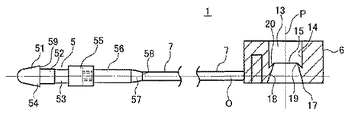
以下に、本発明に係るループピンの一具体例の構成を、図面を参照しながら詳細に説明する。即ち、図1は、本発明に係る当該ループピン1の一具体例の構成を示す平面図であって、図中、可撓性を有するファイバー部7と当該ファイバー部7の一方の端部に設けられた適宜の係合部54を有する挿通頭部5と、前記ファイバー部7の他方の端部に設けられている前記挿通頭部5を不可逆的に通す為の貫通孔13を有するソケット部6とが一体的に形成されたループピン1に於いて、当該挿通頭部5は、当該ファイバー部7との接続部58に向けてその直径が暫時拡大する略紡錘形状或は略円錐形状を有するヘッド部51と、当該ヘッド部51の最大直径部を形成する端部59にその一端部が接続され、当該ヘッド部51の当該最大直径よりも小さい直径を有する略円筒形状から構成された第1の細径部52と、当該第1の細径部52の他方の端部に接続されており、当該第1の細径部52の当該直径よりも小さい直径を有する略円筒形状から構成された第2の細径部53とから構成されており、一方、当該ソケット部6の当該貫通孔13は、当該ファイバー部7の中心軸Oと直交する方向の中心軸線Pを有すると共に、当該貫通孔13内の内壁面14には、当該貫通孔13の当該中心軸線Pと直交する方向に形成された円環状の段差部15が設けられており、且つ当該段差部15は、当該貫通孔13の当該挿通頭部挿入部17近傍から当該貫通孔13の内部に向けた方向に所定の角度を以って連続して形成された第1の傾斜部18と当該第1の傾斜部18の端部19から当該貫通孔13の当該挿通頭部挿入部方向17に向けて当該貫通孔13の内壁部14に向けて所定の角度を以って連続的に形成された第2の傾斜部20とで構成されており、当該円環状の段差部15の最大内径部の直径が、当該ヘッド部51の係合部54である最大直径部の長さよりも小さくなる様に構成されているループピン1が示されている。
Hereinafter, the configuration of a specific example of the loop pin according to the present invention will be described in detail with reference to the drawings. That is, FIG. 1 is a plan view showing a configuration of one specific example of the
即ち、本発明に係る当該ループピン1に有っては、従来のループピン1の当該挿通頭部5が、当該ソケット部4の段差部と係合する羽根状のブレードから構成されたものか、或は当該挿通頭部5の段差部が、当該ソケット部4に設けられた羽根状のブレード部とから構成されているのに対し、当該挿通頭部5を略紡錘形状或は略円錐形状を有するヘッド部51と、当該ヘッド部51の最大直径部の当該最大直径よりも小さい直径を有する略円筒形状から構成された第1の細径部52と、当該第1の細径部52の当該直径よりも小さい直径を有する略円筒形状から構成された第2の細径部53とから構成すると共に、当該ソケット部6に於ける当該貫通孔13内に当該略紡錘形状或は略円錐形状を有するヘッド部51の端部54に形成された係合部59と係合する、当該第1と第2の傾斜部18と20とから形成された段差部15と設けたものである。
That is, in the
本発明に於いては、上記した様な構成を採用した結果、当該ソケット部6内の当該貫通孔13内への当該挿通頭部5の挿入が容易に実行され、当該挿通頭部5の当該ヘッド部51と当該ソケット部6の当該貫通孔13内に設けられた当該段差部15に於ける当該傾斜部18及び20とが相互に適度の変形を伴いながら摺動することによって当該係合操作がスムーズに実行される。
In the present invention, as a result of adopting the configuration as described above, the insertion head 5 is easily inserted into the through
尚、本発明に於いては、必要によって、当該挿通頭部5の当該ヘッド部51に適宜のスリット、溝部或は凹み部62等を予め形成しておく事も可能である。
In the present invention, if necessary, an appropriate slit, groove or
更に、図5は、本発明に係る当該ループピン1の当該挿通頭部5と当該ソケット部6とが相互に係合固定されている接合部63の破断強度を測定する為の測定方法例を説明する図であり、当該接合部63から相互に反対方向に延展するファイバー部7のそれぞれを適宜のグリッパー手段64で把持し、当該両グリッパー手段64を双方のグリッパー手段64が離反する方向に所定の速度(144mm/分)で移動させ、当該ファイバー部に所定の張力を印加して接合部63が破断するか、当該接合部63から当該挿通頭部5が引き抜かれた時点での当該張力を、当該接合部63の破断強度として測定するものである。図5(A)の測定方法では、当該接合部63の部分に直接一方のグリッパー手段64の具体例であるフック部を引っ掛け、同時に、当該ループ部に於ける当該接合部63と対向するファイバー部7の中央部に当該他方のグリッパー手段64であるフック部を引っ掛け、当該両フック部を反対方向に移動させて、当該接合部63の近傍に設けた張力計を用いて当該ファイバー部7に係る張力を測定したものである。一方、図5(B)の測定方法では、当該接合部63の両脇から出ているファイバー部7で形成されるループ部の適宜の2箇所にフック部64を引っ掛け図5(A)の測定方法と同様の方法で当該接合部63の破断強度を測定した。
Further, FIG. 5 illustrates an example of a measuring method for measuring the breaking strength of the joint 63 in which the insertion head 5 and the
当該測定結果を表1に示す。尚、表1中、(A)は、図5(A)の測定方法で測定した場合の測定値を示し、(B)は、図5(B)の測定方法で測定した場合の測定値を示す。 The measurement results are shown in Table 1. In Table 1, (A) shows measured values when measured by the measuring method of FIG. 5 (A), and (B) shows measured values when measured by the measuring method of FIG. 5 (B). Show.

尚、表1中、*が付されているデータは、ファイバー部の未延伸部分が延伸されて延び切った時点の張力を示している。 In Table 1, the data marked with * indicates the tension when the unstretched portion of the fiber portion is stretched and fully extended.
上記測定結果から明らかな様に、本発明に係るループピン1の当該接合部63は、従来のループピンよりも使用原料が少なく、サイズも縮小化されているにも係らず、更には、プロピレン系合成樹脂で構成されているにも係らず、本発明に於ける当該ループピン1の当該接合部63の破断強度は3kg以上であることが判明した。これは、同じ寸法を持つ従来のナイロンで構成されたループピンの破断強度に匹敵するものである。本発明に於ける当該ループピン1が上記したような優れた作用効果を発揮する原因を追究した結果、本発明に於いては、図5に示す様に、一旦当該挿通頭部5の当該ヘッド部51と当該ソケット部6の当該段差部15とが係合した後では、当該ファイバー部7を、当該ソケット部6を中心として所定の張力を印加して左右に引張り、当該挿通頭部5と当該ソケット部4との結合強度を測定する場合に、当該ヘッド部51の最下端部54の当該係合部59の一部と、当該段差部の当該先端部15にある段差部先端部19の一部とが係合する部分では、当該ヘッド部51が当該段差部15の当該先端部19を中心として旋回するような、梃子の中心部としての機能を発揮すると同時に、当該ヘッド部51の最下端部54の当該係合部59の当該段差部15の当該先端部19とは略反対側にある当該ヘッド部51の最下端部54の面は、当該段差部15の当該第2の傾斜面20と密接するように変形するので、当該ヘッド部51は、当該段差部15からの抜け出しがより堅固に防止される事になる。
As is apparent from the above measurement results, the joint 63 of the
然も、本発明に於いては、当該挿通頭部5と当該ソケット部4との結合強度を測定する場合に、当該ファイバー部7を、当該ソケット部6を中心として所定の張力を印加して左右に引っ張る際に、当該挿通頭部5に於ける、特に第2の細径部53が、容易に屈曲乃至は湾曲状に変形する事が可能であるので、当該ファイバー部に印加される所定の張力が直接的に当該挿通頭部5と当該貫通孔13内の当該段差部15との係合部に伝達される事が防止されるので、当該挿通頭部5と当該ソケット部4との結合強度を見かけ上増加させる事に寄与するものである。
However, in the present invention, when measuring the coupling strength between the insertion head 5 and the socket part 4, the
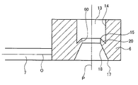
尚、図2は、図1に示されている本発明に係る当該ループピン1の一部断面図を含む側面図であり、図3は、その裏面図である。又、図4は、本発明に於ける当該ソケット部6の当該貫通孔13内に形成された当該段差部15の側部拡大断面図である。
2 is a side view including a partial cross-sectional view of the
本発明に於ける他の具体例としては、例えば、図6に示す様に、当該段差部15に於ける、当該第1と第2の傾斜部18、20の交点部19の近傍に、当該貫通孔13の中心軸線Pと平行に設けられた環状平坦面60が形成されている事が望ましい。本発明に於いては、係る技術構成を採用することによって、当該段差部15に於ける当該先端部19の強度を増大させると共に、当該段差部15に係合する当該ヘッド部51の抜け防止効果を増大させる事が出来る。
As another specific example in the present invention, for example, as shown in FIG. 6, in the vicinity of the
又、本発明に於ける更に別の具体例としては、当該ファイバー部7、当該挿通頭部5及び当該ソケット部6は、ポリプロピレン系合成樹脂により一体的に形成されている事を特徴とするループピンである。
As still another specific example in the present invention, the
更に、本発明に於ける他の具体例としては、例えば、図7に示す様に、当該第1の細径部52の円筒外径表面の少なくとも一部に一本乃至複数本の突起状線状部61を設けると同時に当該突起状線状部61の高さが当該貫通孔13の内壁部14と常時接触する様な値に設定することによって、当該挿通頭部5と当該ソケット部6の当該貫通孔13のない壁面とのが強固に接合され、旋回防止、抜け防止効果を発揮させる事も可能である。
Furthermore, as another specific example of the present invention, for example, as shown in FIG. 7, one or more protruding lines are formed on at least a part of the cylindrical outer diameter surface of the first
(実施例)
以下に、本発明に係る当該ループピン1の具体的な実施例を説明する。即ち、図1乃至4に示す構成を有するループピンを市販のポリプロピレン樹脂を使用して一体的に成形加工した。当該挿通頭部5に於ける当該ヘッド部51の長さを2mm、当該ヘッド部51の下端部54の最大直径部の長さを1.76(好ましくは1.75乃至1.85mm)に設定し、当該第1の細径部52の長さを1.3mm(好ましくは1.20乃至1.35mm)、その直径を1.29(好ましくは1.20乃至1.35mm)に設定すると共に、当該第2の細径部53長さを1.0mm(好ましくは0.8乃至1.3mm)、その直径を1.18mm(好ましくは1.15乃至1.25mm)に設定した。又、ファイバー部の太さを1.17mm(好ましくは、0.70乃至1.18mm)に設定した。
(Example)
Hereinafter, specific examples of the
尚、図中、55は、当該第2の細径部53の端部に接続して形成された拡大径部であり、56は、当該拡大径部55に接続され当該ファイバー部7と接続している未延伸部分である。当該未延伸部分56は、適宜のテーパー部57を介してその端部58で当該ファイバー部7と接合されている。尚、当該拡大径部55、当該未延伸部分56及び当該テーパー部57の形状、或は長さ等は特に限定されるものではないが、それらの直径は、当該ファイバー部7の直径よりも大きくなる様に設定されている。
In the figure, 55 is an enlarged diameter portion formed by connecting to the end of the second
本発明に於ける当該第1の細径部52の直径は、特に限定されるものではないが、当該ヘッド部51の最大直径に対して20乃至35%小さくなる様に設定されている事が好ましい。同様に、当該第2の細径部53の直径は、当該第1の細径部52の直径に対して5乃至25%小さくなる様に設定されている事が望ましい。
The diameter of the first
一方、当該ソケット部6の厚みTを3.0mm、長さLを5.5mm、幅W2.5mmに設定すると共に、当該貫通孔13の内部直径を1.95mmと設定し、更に、当該貫通孔13の当該ソケット部6の下端部に於ける当該挿通頭部5の挿入部17の内部直径を当該貫通孔13の内部直径よりも大きく設定し、2.14mmとした。係る具体例に於ける当該貫通孔13の当該挿通頭部挿入部17の直径は、当該貫通孔本体部13の内径部よりも5乃至10%大きくなる様に構成されている事が望ましい。
On the other hand, the thickness T of the
本具体例では、当該挿通頭部5の挿入部17の周縁部から当該貫通孔13の内部上方に向けて、当該貫通孔13の内壁面14に対して予め定められた角度を持った第1のテーパー部18が所定の長さに亘って形成されており、一方、当該第1のテーパー部18の内部端部19から当該貫通孔13の当該挿通頭部挿入部17の方向に向けて当該貫通孔13の内壁部14に向けて所定の角度を以って連続的に形成された第2の傾斜部20が設けられており、それによって、当該貫通孔13の内部には、先鋭な先端部を有する突起からなる環状の段差部15が形成され、当該段差部15が当該挿通頭部5の係合部59に対する係止部として機能する。本具体例に於ける当該円環状の段差部15の最大内径部の直径は、当該ヘッド部51の最大直径部54の長さよりも小さくなる様に構成されている事が望ましい。
In this specific example, a first angle having a predetermined angle with respect to the
本具体例に於いては、当該第2の傾斜部の当該貫通孔13の内壁面14に対する傾斜角度は、当該第1の傾斜部の同一傾斜角度よりも大きくなる様に設定されている事が望ましい。又、第2の傾斜部20が当該貫通孔13の内壁面と交差する部位63は、当該ソケット部6の上端縁部から2.00mm下がった位置に設けられている事が好ましく、更に当該第2の傾斜部20が当該貫通孔13の内壁面と交差する部位63と当該段差部15の先端部19との位置関係は、当該段差部15の先端部19の位置が、当該第2の傾斜部20が当該貫通孔13の内壁面と交差する部位63よりも0.175mmだけ上方に位置している事が望ましい。
In this specific example, the inclination angle of the second inclined portion with respect to the
又、本発明に於ける、当該具体例に於いて、当該段差部15の最小内径部の直径は、当該挿通部のヘッド部51の最大直径が1.76mmであるのに対して、1.62mmに設定されているが、当該貫通孔13の本体部の内径部に対して、15乃至30%小さくなる様に設定されている事が望ましい。同様に、当該段差部15の最小内径部19の直径は、当該ヘッド部51の最大直径部に対して5乃至20%小さくなる様に設定されている事が好ましい。
In the specific example of the present invention, the diameter of the minimum inner diameter portion of the
1 ループピン
5 挿通頭部
6 ソケット部
7 ファイバー部
13 貫通孔
14 内壁面
15 段差部
58 接続部
51 ヘッド部
59 ヘッド部係合部
52 第1の細径部
53 第2の細径部
13 貫通孔
17 挿通頭部挿入部
18 第1の傾斜部
19 端部
20 第2の傾斜部
54 ヘッド部の最下端部
19 段差部先端部
60 環状平坦面
61 突起状線状部
62 スリット部、溝部
57 テーパー部
55 拡大径部
56 未延伸部分
DESCRIPTION OF
Claims (8)
Priority Applications (5)
| Application Number | Priority Date | Filing Date | Title |
|---|---|---|---|
| JP2009134600A JP2010280410A (en) | 2009-06-04 | 2009-06-04 | Loop pin |
| EP10783497.0A EP2439148A4 (en) | 2009-06-04 | 2010-06-04 | Loop pin |
| CN201080020945XA CN102421680B (en) | 2009-06-04 | 2010-06-04 | Loop pin |
| US13/375,330 US20120085877A1 (en) | 2009-06-04 | 2010-06-04 | Loop pin |
| PCT/JP2010/059896 WO2010140715A1 (en) | 2009-06-04 | 2010-06-04 | Loop pin |
Applications Claiming Priority (1)
| Application Number | Priority Date | Filing Date | Title |
|---|---|---|---|
| JP2009134600A JP2010280410A (en) | 2009-06-04 | 2009-06-04 | Loop pin |
Publications (2)
| Publication Number | Publication Date |
|---|---|
| JP2010280410A true JP2010280410A (en) | 2010-12-16 |
| JP2010280410A5 JP2010280410A5 (en) | 2012-07-19 |
Family
ID=43297846
Family Applications (1)
| Application Number | Title | Priority Date | Filing Date |
|---|---|---|---|
| JP2009134600A Pending JP2010280410A (en) | 2009-06-04 | 2009-06-04 | Loop pin |
Country Status (5)
| Country | Link |
|---|---|
| US (1) | US20120085877A1 (en) |
| EP (1) | EP2439148A4 (en) |
| JP (1) | JP2010280410A (en) |
| CN (1) | CN102421680B (en) |
| WO (1) | WO2010140715A1 (en) |
Cited By (1)
| Publication number | Priority date | Publication date | Assignee | Title |
|---|---|---|---|---|
| KR20190083621A (en) * | 2018-01-04 | 2019-07-12 | 정창원 | Implant for plastic operation of vagina |
Families Citing this family (2)
| Publication number | Priority date | Publication date | Assignee | Title |
|---|---|---|---|---|
| JP6074238B2 (en) * | 2012-11-19 | 2017-02-01 | 株式会社メックモールド | Fastener material |
| CN104376782A (en) * | 2014-11-18 | 2015-02-25 | 嘉善奥南服装辅料有限公司 | Hanging mechanism for clothes hang tag |
Citations (7)
| Publication number | Priority date | Publication date | Assignee | Title |
|---|---|---|---|---|
| US3718355A (en) * | 1971-08-27 | 1973-02-27 | R Canter | Seal |
| US4183567A (en) * | 1974-08-02 | 1980-01-15 | Dennison Manufacturing Company | Attaching device |
| JPS6470346A (en) * | 1987-09-11 | 1989-03-15 | Toska Co Ltd | Connection type bundling jig |
| US6009997A (en) * | 1998-04-02 | 2000-01-04 | Avery Denmson Corporation | Loop fastener, fastener clip including same and loop fastener dispensing tool |
| US6026544A (en) * | 1998-04-02 | 2000-02-22 | Avery Dennison Corporation | Loop fastener, fastener clip including same and loop fastener dispensing tool |
| US6101683A (en) * | 1998-04-02 | 2000-08-15 | Avery Dennison Corporation | Loop fastener, fastener clip including same and loop fastener dispensing tool |
| JP2005206171A (en) * | 2004-01-21 | 2005-08-04 | M I T Internatl:Kk | Loop pin combining device |
Family Cites Families (20)
| Publication number | Priority date | Publication date | Assignee | Title |
|---|---|---|---|---|
| US3816879A (en) * | 1972-10-04 | 1974-06-18 | Dennison Mfg Co | Filamentary string fastener |
| US4059300A (en) * | 1975-11-12 | 1977-11-22 | E. J. Brooks Company | Seal |
| NL7812641A (en) * | 1978-02-17 | 1979-08-21 | Toska Co Ltd En Japan Bano K C | FASTENER. |
| US5048881A (en) * | 1990-05-21 | 1991-09-17 | Renfro Bradley W | Lockable seal ring for an electrical meter |
| US5762386A (en) * | 1995-01-20 | 1998-06-09 | Stoffel Seals Corporation | Tamper resistant seal and method of sealing an object |
| JPH10116034A (en) * | 1996-10-14 | 1998-05-06 | J Ii Kk | Flexible pin material for hanging tag |
| JP3390983B2 (en) * | 1995-05-17 | 2003-03-31 | ジェイ・イー株式会社 | Tag hanging loop pin attachment |
| CN2286982Y (en) * | 1997-03-28 | 1998-08-05 | 福建省石狮市石狮仕林华侨塑料工艺厂 | Mark fastener |
| US5943741A (en) * | 1997-09-19 | 1999-08-31 | Kotec's Co., Ltd. | Label supporting means |
| JP4260910B2 (en) * | 1997-12-02 | 2009-04-30 | 株式会社コーテックス | Sealing tool |
| US6196751B1 (en) * | 1998-09-11 | 2001-03-06 | Thomas & Betts International, Inc. | Stud mounted fastener for routing wire |
| JP2000289727A (en) * | 1999-04-05 | 2000-10-17 | Kotecs Co Ltd | Sealing tool |
| US6446311B1 (en) * | 2000-01-06 | 2002-09-10 | Kotec's Co., Ltd. | Loop pin |
| US6564984B1 (en) * | 2000-04-27 | 2003-05-20 | M.I.T. International Co., Ltd. | Loop pin connecting device |
| JP2002154511A (en) * | 2000-08-30 | 2002-05-28 | Kotecs Co Ltd | Sealer |
| JP2002255132A (en) * | 2001-03-01 | 2002-09-11 | M I T Internatl:Kk | Engagement piece fixing device |
| USD467794S1 (en) * | 2001-12-20 | 2002-12-31 | Kotec's Co., Ltd. | Fastening device |
| JP4100917B2 (en) * | 2002-01-18 | 2008-06-11 | 株式会社コーテックス | Sealing tool |
| US6796479B2 (en) * | 2002-07-04 | 2004-09-28 | M.I.T. International Co., Ltd. | Loop-pin attaching device |
| US7264287B2 (en) * | 2004-01-21 | 2007-09-04 | Henry Kong Sun Ching | Methods and apparatus for facilitating security and tamper control |
-
2009
- 2009-06-04 JP JP2009134600A patent/JP2010280410A/en active Pending
-
2010
- 2010-06-04 CN CN201080020945XA patent/CN102421680B/en not_active Expired - Fee Related
- 2010-06-04 EP EP10783497.0A patent/EP2439148A4/en not_active Withdrawn
- 2010-06-04 WO PCT/JP2010/059896 patent/WO2010140715A1/en active Application Filing
- 2010-06-04 US US13/375,330 patent/US20120085877A1/en not_active Abandoned
Patent Citations (7)
| Publication number | Priority date | Publication date | Assignee | Title |
|---|---|---|---|---|
| US3718355A (en) * | 1971-08-27 | 1973-02-27 | R Canter | Seal |
| US4183567A (en) * | 1974-08-02 | 1980-01-15 | Dennison Manufacturing Company | Attaching device |
| JPS6470346A (en) * | 1987-09-11 | 1989-03-15 | Toska Co Ltd | Connection type bundling jig |
| US6009997A (en) * | 1998-04-02 | 2000-01-04 | Avery Denmson Corporation | Loop fastener, fastener clip including same and loop fastener dispensing tool |
| US6026544A (en) * | 1998-04-02 | 2000-02-22 | Avery Dennison Corporation | Loop fastener, fastener clip including same and loop fastener dispensing tool |
| US6101683A (en) * | 1998-04-02 | 2000-08-15 | Avery Dennison Corporation | Loop fastener, fastener clip including same and loop fastener dispensing tool |
| JP2005206171A (en) * | 2004-01-21 | 2005-08-04 | M I T Internatl:Kk | Loop pin combining device |
Cited By (2)
| Publication number | Priority date | Publication date | Assignee | Title |
|---|---|---|---|---|
| KR20190083621A (en) * | 2018-01-04 | 2019-07-12 | 정창원 | Implant for plastic operation of vagina |
| KR102155525B1 (en) | 2018-01-04 | 2020-09-14 | 정창원 | Implant for plastic operation of vagina |
Also Published As
| Publication number | Publication date |
|---|---|
| CN102421680B (en) | 2013-11-06 |
| EP2439148A4 (en) | 2013-10-02 |
| CN102421680A (en) | 2012-04-18 |
| US20120085877A1 (en) | 2012-04-12 |
| EP2439148A1 (en) | 2012-04-11 |
| WO2010140715A1 (en) | 2010-12-09 |
Similar Documents
| Publication | Publication Date | Title |
|---|---|---|
| US4854014A (en) | Fastener | |
| US7346963B2 (en) | Cord stopper | |
| WO2010140715A1 (en) | Loop pin | |
| JP2001199418A (en) | Loop pin | |
| JP2018532894A (en) | Process for producing improved knitting needles and circular knitting needles | |
| US7654422B2 (en) | Needle threader | |
| JP2014004074A (en) | Strap clasp | |
| US11694581B2 (en) | Tag anchor and method of use | |
| US20120012622A1 (en) | Needle | |
| WO2014102941A1 (en) | Separable connection device for slide fastener, and fastener chain | |
| SE451512B (en) | LABELING PARTS FOR LABELS, GOODS AND LIKE | |
| JP5462950B2 (en) | Slide fastener and method for manufacturing slide fastener stop | |
| JP2009143619A (en) | Unlockable attaching member | |
| JP5305270B2 (en) | Stringer | |
| WO2002070351A1 (en) | Locking element attaching device | |
| JP5965784B2 (en) | Fastening band | |
| JP4121980B2 (en) | Snap fastener | |
| JP4031485B2 (en) | Fastener | |
| EP0263162A1 (en) | A quickly attachable button arrangement. | |
| JP4960522B1 (en) | Tying tool | |
| WO2012043047A1 (en) | Slide fastener and production method for slide fastener stop | |
| JP6385022B1 (en) | Telescopic band | |
| JP2005226736A (en) | Fixing device with barb | |
| US1016360A (en) | Harness-snap. | |
| KR200367392Y1 (en) | Connecting member for round shape rubber band |
Legal Events
| Date | Code | Title | Description |
|---|---|---|---|
| RD04 | Notification of resignation of power of attorney |
Free format text: JAPANESE INTERMEDIATE CODE: A7424 Effective date: 20110415 |
|
| A521 | Request for written amendment filed |
Free format text: JAPANESE INTERMEDIATE CODE: A523 Effective date: 20120531 |
|
| A621 | Written request for application examination |
Free format text: JAPANESE INTERMEDIATE CODE: A621 Effective date: 20120531 |
|
| A02 | Decision of refusal |
Free format text: JAPANESE INTERMEDIATE CODE: A02 Effective date: 20140304 |