EP1186527A2 - Rear wheel suspension structure in motorcycle - Google Patents
Rear wheel suspension structure in motorcycle Download PDFInfo
- Publication number
- EP1186527A2 EP1186527A2 EP01121282A EP01121282A EP1186527A2 EP 1186527 A2 EP1186527 A2 EP 1186527A2 EP 01121282 A EP01121282 A EP 01121282A EP 01121282 A EP01121282 A EP 01121282A EP 1186527 A2 EP1186527 A2 EP 1186527A2
- Authority
- EP
- European Patent Office
- Prior art keywords
- rear wheel
- arm
- rear arm
- arm member
- engine body
- Prior art date
- Legal status (The legal status is an assumption and is not a legal conclusion. Google has not performed a legal analysis and makes no representation as to the accuracy of the status listed.)
- Granted
Links
Images


Classifications
-
- B—PERFORMING OPERATIONS; TRANSPORTING
- B62—LAND VEHICLES FOR TRAVELLING OTHERWISE THAN ON RAILS
- B62K—CYCLES; CYCLE FRAMES; CYCLE STEERING DEVICES; RIDER-OPERATED TERMINAL CONTROLS SPECIALLY ADAPTED FOR CYCLES; CYCLE AXLE SUSPENSIONS; CYCLE SIDE-CARS, FORECARS, OR THE LIKE
- B62K25/00—Axle suspensions
- B62K25/04—Axle suspensions for mounting axles resiliently on cycle frame or fork
- B62K25/12—Axle suspensions for mounting axles resiliently on cycle frame or fork with rocking arm pivoted on each fork leg
- B62K25/14—Axle suspensions for mounting axles resiliently on cycle frame or fork with rocking arm pivoted on each fork leg with single arm on each fork leg
- B62K25/20—Axle suspensions for mounting axles resiliently on cycle frame or fork with rocking arm pivoted on each fork leg with single arm on each fork leg for rear wheel
-
- F—MECHANICAL ENGINEERING; LIGHTING; HEATING; WEAPONS; BLASTING
- F02—COMBUSTION ENGINES; HOT-GAS OR COMBUSTION-PRODUCT ENGINE PLANTS
- F02B—INTERNAL-COMBUSTION PISTON ENGINES; COMBUSTION ENGINES IN GENERAL
- F02B75/00—Other engines
- F02B75/16—Engines characterised by number of cylinders, e.g. single-cylinder engines
- F02B75/18—Multi-cylinder engines
- F02B75/20—Multi-cylinder engines with cylinders all in one line
-
- B—PERFORMING OPERATIONS; TRANSPORTING
- B62—LAND VEHICLES FOR TRAVELLING OTHERWISE THAN ON RAILS
- B62K—CYCLES; CYCLE FRAMES; CYCLE STEERING DEVICES; RIDER-OPERATED TERMINAL CONTROLS SPECIALLY ADAPTED FOR CYCLES; CYCLE AXLE SUSPENSIONS; CYCLE SIDE-CARS, FORECARS, OR THE LIKE
- B62K25/00—Axle suspensions
- B62K25/04—Axle suspensions for mounting axles resiliently on cycle frame or fork
- B62K25/28—Axle suspensions for mounting axles resiliently on cycle frame or fork with pivoted chain-stay
- B62K25/283—Axle suspensions for mounting axles resiliently on cycle frame or fork with pivoted chain-stay for cycles without a pedal crank, e.g. motorcycles
-
- B—PERFORMING OPERATIONS; TRANSPORTING
- B62—LAND VEHICLES FOR TRAVELLING OTHERWISE THAN ON RAILS
- B62M—RIDER PROPULSION OF WHEELED VEHICLES OR SLEDGES; POWERED PROPULSION OF SLEDGES OR SINGLE-TRACK CYCLES; TRANSMISSIONS SPECIALLY ADAPTED FOR SUCH VEHICLES
- B62M7/00—Motorcycles characterised by position of motor or engine
- B62M7/12—Motorcycles characterised by position of motor or engine with the engine beside or within the driven wheel
-
- F—MECHANICAL ENGINEERING; LIGHTING; HEATING; WEAPONS; BLASTING
- F02—COMBUSTION ENGINES; HOT-GAS OR COMBUSTION-PRODUCT ENGINE PLANTS
- F02B—INTERNAL-COMBUSTION PISTON ENGINES; COMBUSTION ENGINES IN GENERAL
- F02B61/00—Adaptations of engines for driving vehicles or for driving propellers; Combinations of engines with gearing
- F02B61/02—Adaptations of engines for driving vehicles or for driving propellers; Combinations of engines with gearing for driving cycles
-
- B—PERFORMING OPERATIONS; TRANSPORTING
- B62—LAND VEHICLES FOR TRAVELLING OTHERWISE THAN ON RAILS
- B62K—CYCLES; CYCLE FRAMES; CYCLE STEERING DEVICES; RIDER-OPERATED TERMINAL CONTROLS SPECIALLY ADAPTED FOR CYCLES; CYCLE AXLE SUSPENSIONS; CYCLE SIDE-CARS, FORECARS, OR THE LIKE
- B62K2202/00—Motorised scooters
-
- F—MECHANICAL ENGINEERING; LIGHTING; HEATING; WEAPONS; BLASTING
- F02—COMBUSTION ENGINES; HOT-GAS OR COMBUSTION-PRODUCT ENGINE PLANTS
- F02B—INTERNAL-COMBUSTION PISTON ENGINES; COMBUSTION ENGINES IN GENERAL
- F02B75/00—Other engines
- F02B75/16—Engines characterised by number of cylinders, e.g. single-cylinder engines
- F02B75/18—Multi-cylinder engines
- F02B2075/1804—Number of cylinders
- F02B2075/1808—Number of cylinders two
Definitions
- the present invention relates to a motorcycle in which a rear wheel is supported rotatably by a pair of rear arms, the rear arms being supported vertically swingably by an engine body mounted on a body frame.
- the invention concerns a rear wheel suspension structure for suspending a rear wheel.
- both rear arms are constructed of a unitary piece of member from their front portions supported by the engine body up to their rear portions which support the rear wheel.
- the whole of the second rear arm supported vertically pivotably by the engine body may be removed to omit removal of the axle, but in this case it is necessary to take some measure for preventing the adhesion of dust to a bearing portion of the second rear arm. Therefore, removal of the whole of the second rear arm should be avoided in servicing the rear wheel.
- an object of the invention is to provide a rear wheel suspension structure, for a motorcycle, capable of improving the rear wheel servicing performance while eliminating the need of considering a measure against the adhesion of dust to the bearing portion of the second rear arm when servicing the rear wheel.
- a motorcycle in which an engine body of an engine is mounted on a body frame non-swingably and a rear wheel is disposed between and supported rotatably by a first rear arm and a second rear arm, the first rear arm being supported vertically swingably by the engine body and constituting a part of a case which incorporates a power train system for transmitting power from the engine to the rear wheel, the second rear arm being supported by the engine body vertically swingably about an axis which is coaxial with a swing axis of the first rear arm, there is provided a rear wheel suspension structure wherein the second rear arm comprises a plurality of arm members, including a front arm member supported swingably by the engine body and a rear arm member which supports the axle of the rear wheel rotatably, the plural arm members being connected together so that they can be disconnected from each other.
- the rear wheel can be removed sideways on the side opposite to the first rear arm without pulling out the axle. Also at the time of mounting of the rear wheel all that is required is merely passing the axle as supported on the first rear arm side through the rear wheel and mounting the rear arm member, whereby the rear wheel servicing performance can be improved in comparison with the conventional structure in which the axles is passed through the rear wheel is being raised and is established its position. Besides, the portion of the second rear arm where the second rear arm is supported by the engine body is not disassembled in servicing the rear wheel and there is no fear of dust adhesion to the bearing portion of the second rear arm. Thus, it is not necessary to consider taking any measure against the adhesion of dust.
- a rear wheel suspension structure wherein, in addition to the configuration of the invention defined in claim 1, the front arm member is connected separably to the first rear arm between the engine body and the rear wheel, and the rear arm member is connected separably to the front arm member while maintaining the connected state of the front arm member to the first rear arm.
- a rear wheel suspension structure wherein, in addition to the construction of the invention defined in claim 1 or 2, the axle of the rear wheel and a final output shaft of the power train system are contiguous to each other coaxially and integrally. With this configuration, the final output shaft of the power train system also serves as the rear wheel axle, whereby the construction of the power train system can be simplified.
- a rear wheel suspension structure wherein, in addition to the construction of the invention defined in claim 1, in the rear arm, the front arm member is connected separably to the rear arm member which is capable of being connected separably to the first rear arm between the engine body and the rear wheel.
- the rear wheel can be removed sideways on the side opposite to the first rear arm, and also at the time of mounting the rear wheel it suffices to pass the axle as supported on the first rear arm side through the rear wheel and install the rear arm member, and thus it is possible to improve the rear wheel servicing performance. Besides, since it is not necessary that the whole of the second rear arm is removed, and there is no fear of dust adhesion to the bearing portion of the second rear arm, it is not necessary to consider any measure against the adhesion of dust.
- the first and second rear arms are interconnected between the engine body and the rear wheels, thereby making it possible to prevent the occurrence of twist between both rear arms, and at the same time the rear wheel can be removed outwardly sideways without disassembling the interconnection, whereby the rear wheel servicing performance can be further improved.
- the rear arm member in the second rear arm, the first rear arm connected to the rear arm member, and the rear wheel supported through the axle by the rear arm member and the first rear arm can be subassembled, so that both rear arms which support the rear wheel through the axle can be installed easily to the engine body and thus it is possible to improve the rear wheel installing performance.
- Figs. 1 to 4 illustrate the first embodiment of the present invention.
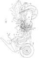
- Fig. 1 is a partially cut-away side view of a scooter type motorcycle
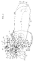
- Fig. 2 is a plan view of an engine with a seat omitted
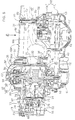
- Fig. 3 is a partially cut-away side view of an engine body and a case
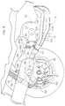
- Fig. 4 is a sectional view taken on line 4-4 in Fig. 3.
- a head pipe 5 is disposed at a front end of a body frame F of the scooter type motorcycle, a steering shaft 7, with a steering handle 6 provided at an upper end thereof, is supported steerably by the head pipe 5, and a front fork 8 is connected to a lower end of the steering shaft 7, and a front wheel WF is supported rotatably by a lower portion of the front fork 8.
- the body frame F is covered with a cover 9, and behind the cover 9 are mounted a main seat 10 for a rider and a pillion seat 11 for a fellow passenger, the pillion seat 11 being located behind the main seat 10.
- the pillion seat 11 is attached to the cover 9 so that it can be opened and closed.
- a container box 13 for receiving a pair of helmets 12, etc. therein is mounted to a rear portion of the body frame F so that an upper-end opening thereof can be closed with the pillion seat 11.
- the cover 9 is provided with a pair of right and left step floors 14 for the rider sitting on the main seat 10 to put his or her feet thereon and is also provided with a floor tunnel cover 15 which is raised upward between the step floors 14.
- an engine body 16 of an engine E which is, for example, a two-cylinder engine is supported non-swingably by the body frame F below the main seat 10.
- the engine body 16 is made up of a cylinder block 20 having a pair of cylinder bores 24 which are parallel to each other, a crankcase 21 which supports a crankshaft 27 rotatably and which is coupled to the cylinder block 20, the crankshaft being connected through a pair of connecting rods 26 to a pair of pistons 25 which are slidably fitted in the cylinder bores 24 respectively, a cylinder head 22 coupled to the cylinder block 20 in such a manner that a pair of combustion chambers 28 in which the pistons 25 face are formed between the cylinder head and the cylinder block, and a head cover 23 coupled to the cylinder head 22 on the side opposite to the cylinder block 20.
- Support arm portions 30 and 31 are provided in a front lower portion and a rear upper portion, respectively, of the crankcase 21 and a support arm portion 32 is provided in a lower portion of the cylinder head 22.
- the support arm portions 30 to 32 are connected to the body frame F, whereby the engine body 16 is supported by the body frame F non-swingably.
- the engine body 16 assumes a posture in which the axes of the paired cylinder bores 24 arranged in the transverse direction of the body frame F are inclined forwardly upwardly.
- the crankcase 21 comprises left and right crankcase halves 34L, 34R coupled together, and a case cover 36 is fastened to the right crankcase half 34R so as to define a generator chamber 35 between the right crankcase half 34R and the same.
- an outer rotor 38 is fixed to the crankshaft 27, and an inner stator 39 which constitutes an AC generator 37 in cooperation with the outer rotor 38 is fixed to the case cover 36.
- a front portion of a first rear arm 40L disposed on the left-hand side of the rear wheel WR and a front portion of a second rear arm 40R disposed on the right-hand side of the rear wheel WR are supported by the crankcase 21 in the engine body 16 so as to be vertically swingably about an axis coaxial with the axis of the crankshaft 27.
- the rear wheel WR is supported between the rear arms 40L and 40R through an axle.
- the first rear arm 40L constitutes a part of a case 18 which incorporates a power train system 29 for transmitting power from the engine E to the rear wheel WR.
- the case 18 is constituted by both the first rear arm 40L and a cover 41 which covers the first rear arm from outside.
- the cover 41 is provided with a cover inner wall 42 fastened to the first rear arm 40L and a cover outer wall 43 which is fastened to the cover inner wall 42 so as to provide a spacing between an outer surface of the cover inner wall 42 and the same.
- a rear cushion 19 is disposed between a rear portion of the case 18 and the body frame F.
- a ring-like support member 44 is fastened to an outer surface of the left case halve 34L of the crankcase 21 so as to coaxially surround the crankshaft 27 which extends rotatably through the left case half 34L into the case 18.
- the front portion of the first rear arm 40L is supported by the support member 44 rotatably through a ball bearing 45.
- the second rear arm 40R is made up of a front arm member 47 which is supported vertically swingably by the crankcase 21 in the engine body 16 and a rear arm member 48 which is connected to the front arm member 47 separably. Between the rear arm member 48 which supports the rear wheel WR through the axle and the body frame F is mounted a rear cushion of the same structure as the rear cushion 19 disposed between the rear portion of the case 18 and the body frame F.
- the front arm member 47 is formed so as to extend sideways of the case cover 36 and lap on the back side of the crankcase 21 curvilinearly.
- a pivot shaft 50 coaxial with the crankshaft 27 and connected to a front portion of the front arm member 47 is supported by the case cover 36 rotatably through a roller bearing 49.
- a connection 40a lapping on the back side of the crankcase 21 is integral with the first rear arm 40L and the front arm member 47 of the first rear arm 40R is fastened to the connection 40a with bolts 46.
- the front arm member 47 of the second rear arm 40R is separably connected to the first rear arm 40L between the engine body 16 and the rear wheel WR. That is, the first and second rear arms 40L, 40R are interconnected between the engine body 16 and the rear wheel WR and are thereby supported by the engine body 16 so as to be vertically swingably about an axis coaxial with the crankshaft 27 while preventing the occurrence of twist of both rear arms.
- the rear arm member 48 of the second rear arm 40R is connected to the front arm member 47 with plural bolts 60 so as to be separable from the front arm member 47 while maintaining the connected state of the front arm member 47 to the first rear arm 40L.
- the power train system 29 includes a transmission 17 which shifts the power of the crankshaft 27 in a stepless manner and a reduction gear train 58 decelerates the output of the transmission 17 and transmits the thusreduced output to the rear wheel WR.
- the transmission 17 is a conventional, known belt type transmission in which an endless belt 53 is wound on both a driving pulley 51 mounted on the crankshaft 27 and a driven pulley 52 connected to an output shaft 55 through a centrifugal clutch 54.
- an effective radius of the driving pulley 51 increases and that of the driven pulley 52 decreases, whereby a gear ratio can be shifted from LOW to TOP in a stepless manner.
- a support wall 56 is fatened to the first rear arm 40L and the output shaft 55 of the transmission 17 is supported rotatably by both first rear arm 40L and support wall 56.
- the reduction gear train 58 is disposed between the output shaft 55 of the transmission 27 and a final output end, i.e. a final output shaft 59 of the power train system 29 and is accommodated between the first rear arm 40L and the support wall 56.
- the final output shaft 59 is supported rotatably by the first rear arm 40L through a ball bearing 85 and also by the support wall 56 through a ball bearing 86.
- An axle 57 is contiguous to the final output shaft 59 coaxially and integrally.
- the axle 57 extends through a hub 87 of the rear wheel WR and both axle 57 and hub 87 are splined to each other to prevent a relative rotation.
- the axle 57 is supported by the rear arm member 48 in the second rear arm 40R rotatably through a ball bearing 88, and a cylindrical spacer 89 which surrounds the axle 57 is interposed between an inner ring of the ball bearing 88 positioned on the rear arm member 48 side and an inner ring of the ball bearing 85 positioned on the first rear arm 40L side.
- a nut 90 is threadedly engaged with an outer end portion of the axle 57 at an outer position with respect to the ball bearing 88, with a ring plate 91 being interposed between the nut and the inner ring of the ball bearing 88.
- the hub 87 of the rear wheel WR and the spacer 89 are sandwiched in between the inner rings of the ball bearings 85 and 88.
- the nut 90 is loosened and so are the bolts 60 to disconnect the rear arm member 48 from the front arm member 47, it is possible to remove the rear arm member 48 outwardly sideways along the axis of the axle 57 and further remove the spacer 89 and the rear wheel WR outwardly sideways along the axis of the axle 57.
- the position of connection between the front and rear arm members 47 and 48 is determined so that the front arm member 47 may not be an obstacle to the removal of the rear wheel WR.
- an air cleaner 61 for cooling is disposed between the cover inner wall 42 and the cover outer wall 43, whereby air for cooling the belt type transmission 17 is directed from the exterior of the transmission case 18 to the interior thereof through the cooling air cleaner 61.
- a sound absorbing material 62 is sandwiched in between the cover inner wall 42 and the cover outer wall 43 and thus cover 41 in the rear portion of the case 18 is constructed so as to have a soundproof structure.
- intake ports 64 so as to be open obliquely upwardly and correspondingly each individually to the combustion chambers 28 and are also formed exhaust ports 65 so as to be open downward and correspondingly each individually to the combustion chambers 28.
- an exhaust system which includes an exhaust muffler 66 (see Fig. 1) disposed on the right-hand side of the rear wheel WR is connected to both exhaust ports 65.
- Intake valves 67 for opening and closing between the intake ports 64 and the combustion chambers 28 are disposed in the cylinder head 22 in a pair for each combustion chamber 28 and exhaust valves 68 for opening and closing between the exhaust ports 6 and the combustion chambers 28 are disposed in a pair for each combustion chamber 28. Further, an intake-side cam shaft 69 for opening and closing the intake valves 67 and an exhaust-side cam shaft 70 for opening and closing the exhaust valves 68 are supported in the cylinder head 22 so that their axes are parallel to the crankshaft 27. A chain chamber 71 in which one ends of the cam shafts 69 and 70 face is formed through the crankcase 21, cylinder block 20, cylinder head 22 and head cover 23 so as to communicate with the generator chamber 35.
- a driving sprocket 72 is integrally provided on the crankshaft 27 at a portion corresponding to the chain chamber 71, and an endless timing chain 74 adapted to travel within the chain chamber 71 is wound on all of a driven sprocket 73 fixed to one end of the intake-side cam shaft 70, a driven sprocket (not shown) fixed to one end of the exhaust-side cam shaft 71, and the driving sprocket 72.
- a pair of throttle bodies 78 are each provided with a throttle valve 77 and have substantially parallel axes below the main seat 10. Upstream ends of a pair of intake pipes 76 are connected to downstream ends of the throttle bodies 78 through connecting hoses 83, while downstream ends of the intake pipes 76 are connected to the intake ports 64 in the cylinder head 22.
- Each intake pipe 76 comprises a rear portion extending forward substantially horizontally from the associated throttle body 78 having a substantially horizontal axis and a front portion communicating with the associated intake port 64 and extending obliquely backward, the rear and front portions being contiguous to each other through a curved portion.
- a pair of fuel injection valves 79 which are covered from above with the main seat 10, are attached to the curved portions of the intake pipes 76 respectively in a posture which permits direct injection of fuel toward the intake valves 67. Rear ends of the fuel injection valves 79 are connected in common to a fuel rail 82.
- Upstream ends of the throttle bodies 78 are connected in common to an intake chamber 80 disposed in front of the container box 13.
- the intake chamber 80 is connected to an air cleaner 81 which is disposed on the right-hand side of the container box 13, namely, on the right-hand side of the rear wheel WR, and above the exhaust muffler 66. Since the exhaust muffler 66 and the air cleaner 81 are disposed without swing motion on the right-hand side of the rear wheels WR, a wide space which permits swing motion of the case 18 of the transmission 17 can be ensured on the left-hand side of the rear wheel WR while ensuring required capacities of the exhaust muffler 66 and air cleaner 81.
- the intake system of the engine E does not swing, either, including throttle bodies 78 having generally horizontal axes below the main seat, intake pipes 76 connecting between the intake ports 64 in the engine body 16 and the throttle bodies 78, fuel injection valves 79 attached to the intake pipes 76, intake body 80, and air cleaner 81.
- the engine body 16 is supported by the body frame F in a state in which the axes of the paired cylinder bores 24 provided in the engine body are inclined forwardly upwardly, a space for disposing therein a rear portion of an auxiliary device, e.g., fuel tank 33, can be ensured while avoiding an increase in size of the scooter type motorcycle.
- an auxiliary device e.g., fuel tank 33
- both cylinder bores 24 are formed in the engine body 16 so as to be arranged in the transverse direction of the body frame F, it is possible to attain a large displacement of the engine E while avoiding an increase in height of the main seat 10.
- the case 18 is supported swingably by the crankcase 21 in the engine body 16, but since the swing axis of the case 18 is coaxial with the axis of the driving pulley 51 in the transmission 17 which is a belt type continuously variable transmission, i.e., coaxial with the axis of the crankshaft 27, a swing motion of the case 18 does not exert an excessive load on the endless belt 53 of the transmission 17.
- the rear wheel WR is supported rotatably by the first and second rear arms 40L, 40R which are disposed on both sides of the rear wheel and which are supported vertically swingably by the engine body 16, and the second rear arm 40R comprises the front arm member 47 supported swingably by the engine body 16 and the rear arm member 48 connected to the front arm member 47 separably, the axle 57 of the rear wheel WR being supported rotatably by the rear arm member 48.
- the rear wheel WR can be removed sideways on the side opposite to the first rear arm 40L. Also when mounting the rear wheel WR, all that is required is merely moving the rear wheel WR toward the first rear arm 40L sideways from the outside while inserting the axle as supported on one end side by the first rear arm 40L into the hub 87, mounting the rear arm member 48 to the front arm member 47 and allowing the opposite end side of the axle 57 to be supported by the rear arm member 48. Therefore, the servicing performance for the rear wheel WR can be improved in comparison with the conventional rear wheel suspending structure in which the axle 57 is inserted through both rear arms and the rear wheel WR while the rear wheel is established its position while being raised.
- the front arm member 47 in the second rear arm 40R is kept connected to the engine body 16 and the supported portion of the second rear arm 40R with respect to the engine body 16 is not disassembled, there is no fear of entry of dust into the bearing portion of the second rear arm 40R and hence it is not necessary to consider taking any measure against the adhesion of dust.
- the front arm member 47 in the second rear arm 40R is connected separably to the first rear arm 40L between the engine body 16 and the rear wheel WR. Consequently, the first and second rear arms 40L, 40R are interconnected between the engine body 16 and the rear wheel WR and are supported by the engine body 16 vertically swingably about an axis coaxial with the crankshaft 27 while preventing mutual twist.
- the rear arm member 48 is connected to the front arm member 47 separably while keeping the front arm member 47 connected to the first rear arm 40L, it becomes possible to remove the rear wheel WR outwardly sideways without disassembling the connection of the first and second rear arms 40L and 40R.
- the servicing performance for the rear wheel WR can be improved to a still greater extent.
- the construction of the power train system 29 can be simplified by allowing the final output shaft 59 to serve also as the axle 57.
- FIGs. 5 and 6 illustrate the second embodiment of the present invention, in which the portions corresponding to the above first embodiment are identified by the same reference numerals as in the first embodiment.
- a front portion of a first rear arm 40L' disposed on the left-hand side of a rear wheel WR and a front portion of a second rear arm 40R' disposed on the right-hand side of the rear wheel WR are supported by a crankcase 21 in the engine body 16 so as to be vertically swingably about an axis coaxial with the axis of a crankshaft 27.
- the rear wheel WR is supported between rear portions of the rear arms 40L' and 40R'.
- the front portion of the first rear arm 40L' is supported rotatably through a ball bearing 45 by a ring-like support member 44 which is fastened to an outer surface of a left case half 34L of the crankcase 21.
- a case 18' which incorporates a power train system 29 is constituted by both the first rear arm 40L' and a cover 41 which is fastened to the first rear arm 40L'.
- the second rear arm 40R' is made up of a front arm member 47' which is supported vertically swingably by the crankcase 21 in the engine body 16, an intermediate arm member 92 connected to the front arm member 47' separably, and a rear arm member 48' connected to the intermediate arm member 92 separably.
- a rear cushion 19 is disposed between the rear arm member 48' which supports the rear wheel WR through an axle and a body frame F.
- crankcase cover 36' which forms a generator chamber 35 between the crankcase half 34R and the same.
- a cylindrical pivot shaft 93 coaxial with the crankshaft 27 is fastened to an outer surface of the case cover 36'.
- the front arm member 47' is formed so as to extend sideways from the case cover 36' and lap on the back side of the crankcase 21, and a front portion of the front arm member 47' is supported by the pivot shaft 93 pivotably through a roller bearing 94.
- the intermediate arm member 92 is disposed between the engine body 16 and the rear wheel WR and the front arm member 47' is connected separably to a right end portion of the intermediate arm member 92 with plural bolts 95.
- first rear arm 40L' is connected separably to a left end portion of the intermediate arm member 92 with plural bolts 96.
- first and second rear arms 40L' and 40R' are interconnected between the engine body 16 and the rear wheel WR and are supported by the engine body 16 vertically swingably about an axis coaxial with the crankshaft 27 while preventing the occurrence of mutual twist.
- the rear arm member 48' in the second rear arm 40R' is connected separably to the right end portion of the intermediate arm member 92 with plural bolts 97 independently of the front arm member 47'.
- the rear arm member 48' is connected separably to the intermediate arm member 92 and separably from the front arm member 47' while maintaining the connected state of the front arm member 47' to the first rear arm 40L' through the intermediate arm member 92.
- a caliper body 99 which constitutes a part of a rear wheel disc brake BR together with a brake disc 98 fixed to the rear wheel WR is supported by the rear arm member 48 in the second rear arm 40R', and also supported thereby is a caliper body 100 which constitutes a part of a parking brake BP together with the brake disc 98.
- a pair of exhaust pipes 101 and 102 are connected at upstream ends thereof to a lower portion of a cylinder head 22 in the engine body 16 and extend backward while passing below and the right-hand side of the engine body 16. Downstream ends of the exhaust pipes 101 and 102 are connected in common to an exhaust muffler 66 which is disposed outside the rear arm member 48' and which is supported by the body frame F.
- the rear wheel WR installing performance can be improved. That is, since the front arm member 47' in the second rear arm 40R' is connected separably to the rear arm 48' which is separably connected to the first rear arm 40L' through the intermediate arm member 92 disposed between the engine body 16 and the rear wheel WR, the rear arm member 48' in the second rear arm 40R', the first rear arm 40L' connected to the rear arm member 48' through the intermediate arm member 92, and the rear wheel WR supported through the axle by the rear arm member 48' and the first rear arm 40L', can be subassembled.
- both rear arms 40L' and 40R' which support the rear wheel WR through the axle can be installed to the engine body 16 and thus the rear wheel WR installing performance can be improved.
- a motorcycle in which an engine body is mounted on a body frame non-swingably and a rear wheel is disposed between and supported rotatably by a first rear arm and a second rear arm, the first rear arm being supported vertically swingably by the engine body and constituting a part of a case which incorporates a power train system for transmitting power from the engine to the rear wheel, the second rear arm being supported by the engine body vertically swingably about an axis which is coaxial with a swing axis of the first rear arm, it is intended to improve the rear wheel servicing performance while eliminating the need of considering a measure against the adhesion of dust to a bearing portion of the second rear arm in servicing the rear wheel.
- the second rear arm 40R includes plural arm members 47 and 48, including a front arm member 47 supported swingably by the engine body 16 and a rear arm member 48 which supports the axle of the rear wheel WR rotatably, the plural arm members being connected together so that they can be disconnected from each other.
Landscapes
- Engineering & Computer Science (AREA)
- Mechanical Engineering (AREA)
- Chemical & Material Sciences (AREA)
- Combustion & Propulsion (AREA)
- General Engineering & Computer Science (AREA)
- Transportation (AREA)
- Axle Suspensions And Sidecars For Cycles (AREA)
Abstract
Description
- The present invention relates to a motorcycle in which a rear wheel is supported rotatably by a pair of rear arms, the rear arms being supported vertically swingably by an engine body mounted on a body frame. In particular, the invention concerns a rear wheel suspension structure for suspending a rear wheel.
- A motorcycle in which a rear wheel is supported rotatably by a pair of rear arms, the rear arms being supported vertically swingably by an engine body, is already known well, for example, in Japanese Patent Laid-open No. 301563/1999. In this known vehicle, both rear arms are constructed of a unitary piece of member from their front portions supported by the engine body up to their rear portions which support the rear wheel.
- In the conventional rear wheel suspension structure referred to above, when a service work is to be performed such as the replacement of a rear wheel tire, an axle inserted through the rear wheel extractably is pulled out and then the rear wheel is removed. When the rear wheel thus removed is to be mounted, it is necessary that the rear wheel be established its position while being raised between both rear arms and that in this state the axle be inserted through both rear arms and the rear wheel to mount the rear wheel. Thus, the rear wheel servicing performance is poor.
- For servicing the rear wheel, the whole of the second rear arm supported vertically pivotably by the engine body may be removed to omit removal of the axle, but in this case it is necessary to take some measure for preventing the adhesion of dust to a bearing portion of the second rear arm. Therefore, removal of the whole of the second rear arm should be avoided in servicing the rear wheel.
- In view of the foregoing, the present invention has been made, and an object of the invention is to provide a rear wheel suspension structure, for a motorcycle, capable of improving the rear wheel servicing performance while eliminating the need of considering a measure against the adhesion of dust to the bearing portion of the second rear arm when servicing the rear wheel.
- For achieving the above-mentioned object, according to the invention defined in
claim 1, in a motorcycle in which an engine body of an engine is mounted on a body frame non-swingably and a rear wheel is disposed between and supported rotatably by a first rear arm and a second rear arm, the first rear arm being supported vertically swingably by the engine body and constituting a part of a case which incorporates a power train system for transmitting power from the engine to the rear wheel, the second rear arm being supported by the engine body vertically swingably about an axis which is coaxial with a swing axis of the first rear arm, there is provided a rear wheel suspension structure wherein the second rear arm comprises a plurality of arm members, including a front arm member supported swingably by the engine body and a rear arm member which supports the axle of the rear wheel rotatably, the plural arm members being connected together so that they can be disconnected from each other. - With this configuration, by separating the rear arm member out of the components of the second rear arm, the rear wheel can be removed sideways on the side opposite to the first rear arm without pulling out the axle. Also at the time of mounting of the rear wheel all that is required is merely passing the axle as supported on the first rear arm side through the rear wheel and mounting the rear arm member, whereby the rear wheel servicing performance can be improved in comparison with the conventional structure in which the axles is passed through the rear wheel is being raised and is established its position. Besides, the portion of the second rear arm where the second rear arm is supported by the engine body is not disassembled in servicing the rear wheel and there is no fear of dust adhesion to the bearing portion of the second rear arm. Thus, it is not necessary to consider taking any measure against the adhesion of dust.
- According to the invention defined in claim 2, there is provided a rear wheel suspension structure wherein, in addition to the configuration of the invention defined in
claim 1, the front arm member is connected separably to the first rear arm between the engine body and the rear wheel, and the rear arm member is connected separably to the front arm member while maintaining the connected state of the front arm member to the first rear arm. With this configuration, the rear wheel can be removed outwardly sideways without disassembling the connection between the first and second rear arms while preventing the occurrence of twist of both rear arms which are connected together between the engine body and the rear wheel, and thus the rear wheel servicing performance can be further improved. - According to the invention defined in claim 3, there is provided a rear wheel suspension structure wherein, in addition to the construction of the invention defined in
claim 1 or 2, the axle of the rear wheel and a final output shaft of the power train system are contiguous to each other coaxially and integrally. With this configuration, the final output shaft of the power train system also serves as the rear wheel axle, whereby the construction of the power train system can be simplified. - Further, according to the invention defined in
claim 4 there is provided a rear wheel suspension structure wherein, in addition to the construction of the invention defined inclaim 1, in the rear arm, the front arm member is connected separably to the rear arm member which is capable of being connected separably to the first rear arm between the engine body and the rear wheel. With this configuration, by subassembling the rear arm member in the second rear arm, the first rear arm connected to the rear arm member, and the rear wheel supported through the axle by the rear arm member and the first rear arm, and by mounting the first rear arm to the engine body, mounting the front arm member which constitutes a part of the second rear arm and connecting it to the rear arm member, both rear arms which support the rear wheel through the axle can be installed to the engine body and thus the rear wheel installing performance can be improved. - According to the invention described in
claim 1, the rear wheel can be removed sideways on the side opposite to the first rear arm, and also at the time of mounting the rear wheel it suffices to pass the axle as supported on the first rear arm side through the rear wheel and install the rear arm member, and thus it is possible to improve the rear wheel servicing performance. Besides, since it is not necessary that the whole of the second rear arm is removed, and there is no fear of dust adhesion to the bearing portion of the second rear arm, it is not necessary to consider any measure against the adhesion of dust. - According to the invention described in claim 2, the first and second rear arms are interconnected between the engine body and the rear wheels, thereby making it possible to prevent the occurrence of twist between both rear arms, and at the same time the rear wheel can be removed outwardly sideways without disassembling the interconnection, whereby the rear wheel servicing performance can be further improved.
- According to the invention described in claim 3, by allowing the final output shaft in the power train system to serve also as the axle of the rear wheel, the construction of the power train system can be simplified.
- Further, according to the invention described in
claim 4, the rear arm member in the second rear arm, the first rear arm connected to the rear arm member, and the rear wheel supported through the axle by the rear arm member and the first rear arm, can be subassembled, so that both rear arms which support the rear wheel through the axle can be installed easily to the engine body and thus it is possible to improve the rear wheel installing performance. - Hereinafter, embodiments of the present invention will be described with reference to the accompanying drawings, in which:
- Fig. 1 is a partially cut-away side view of a scooter type motorcycle according to the first embodiment of the present invention;
- Fig. 2 is a plan view of an engine with a seat omitted;
- Fig. 3 is a partially cut-away side view of an engine body and a case;
- Fig. 4 is a sectional view taken on line 4-4 in Fig. 3;
- Fig. 5 is a sectional view corresponding to Fig. 4 according to the second embodiment of the present invention; and
- Fig. 6 is a view as seen in the direction of
arrow 6 in Fig. 5. -
- Figs. 1 to 4 illustrate the first embodiment of the present invention. Fig. 1 is a partially cut-away side view of a scooter type motorcycle; Fig. 2 is a plan view of an engine with a seat omitted; Fig. 3 is a partially cut-away side view of an engine body and a case; and Fig. 4 is a sectional view taken on line 4-4 in Fig. 3.
- First in Fig. 1, a
head pipe 5 is disposed at a front end of a body frame F of the scooter type motorcycle, asteering shaft 7, with asteering handle 6 provided at an upper end thereof, is supported steerably by thehead pipe 5, and a front fork 8 is connected to a lower end of thesteering shaft 7, and a front wheel WF is supported rotatably by a lower portion of the front fork 8. - The body frame F is covered with a
cover 9, and behind thecover 9 are mounted amain seat 10 for a rider and apillion seat 11 for a fellow passenger, thepillion seat 11 being located behind themain seat 10. Thepillion seat 11 is attached to thecover 9 so that it can be opened and closed. Acontainer box 13 for receiving a pair ofhelmets 12, etc. therein is mounted to a rear portion of the body frame F so that an upper-end opening thereof can be closed with thepillion seat 11. Thecover 9 is provided with a pair of right and left step floors 14 for the rider sitting on themain seat 10 to put his or her feet thereon and is also provided with afloor tunnel cover 15 which is raised upward between the step floors 14. - Referring also to Figs. 2 to 4, an
engine body 16 of an engine E which is, for example, a two-cylinder engine is supported non-swingably by the body frame F below themain seat 10. - The
engine body 16 is made up of acylinder block 20 having a pair ofcylinder bores 24 which are parallel to each other, acrankcase 21 which supports acrankshaft 27 rotatably and which is coupled to thecylinder block 20, the crankshaft being connected through a pair of connectingrods 26 to a pair ofpistons 25 which are slidably fitted in thecylinder bores 24 respectively, acylinder head 22 coupled to thecylinder block 20 in such a manner that a pair ofcombustion chambers 28 in which thepistons 25 face are formed between the cylinder head and the cylinder block, and ahead cover 23 coupled to thecylinder head 22 on the side opposite to thecylinder block 20. -
Support arm portions crankcase 21 and asupport arm portion 32 is provided in a lower portion of thecylinder head 22. Thesupport arm portions 30 to 32 are connected to the body frame F, whereby theengine body 16 is supported by the body frame F non-swingably. When thus supported by the body frame F, theengine body 16 assumes a posture in which the axes of the pairedcylinder bores 24 arranged in the transverse direction of the body frame F are inclined forwardly upwardly. - Since the
engine body 16 is thus supported by the body frame F while the axes of thecylinder bores 24 are inclined forwardly upwardly, an empty space is formed in front of theengine body 16 and afuel tank 33 is mounted to a front portion of the body frame F in such a manner that a rear portion thereof is located within the said empty space. - The
crankcase 21 comprises left andright crankcase halves case cover 36 is fastened to theright crankcase half 34R so as to define agenerator chamber 35 between theright crankcase half 34R and the same. Within thegenerator chamber 35, anouter rotor 38 is fixed to thecrankshaft 27, and aninner stator 39 which constitutes anAC generator 37 in cooperation with theouter rotor 38 is fixed to thecase cover 36. - A front portion of a first
rear arm 40L disposed on the left-hand side of the rear wheel WR and a front portion of a secondrear arm 40R disposed on the right-hand side of the rear wheel WR are supported by thecrankcase 21 in theengine body 16 so as to be vertically swingably about an axis coaxial with the axis of thecrankshaft 27. The rear wheel WR is supported between therear arms - The first
rear arm 40L constitutes a part of acase 18 which incorporates apower train system 29 for transmitting power from the engine E to the rear wheel WR. Thecase 18 is constituted by both the firstrear arm 40L and acover 41 which covers the first rear arm from outside. Thecover 41 is provided with a coverinner wall 42 fastened to the firstrear arm 40L and a coverouter wall 43 which is fastened to the coverinner wall 42 so as to provide a spacing between an outer surface of the coverinner wall 42 and the same. Further, arear cushion 19 is disposed between a rear portion of thecase 18 and the body frame F. - A ring-
like support member 44 is fastened to an outer surface of the left case halve 34L of thecrankcase 21 so as to coaxially surround thecrankshaft 27 which extends rotatably through theleft case half 34L into thecase 18. The front portion of the firstrear arm 40L is supported by thesupport member 44 rotatably through a ball bearing 45. - The second
rear arm 40R is made up of afront arm member 47 which is supported vertically swingably by thecrankcase 21 in theengine body 16 and arear arm member 48 which is connected to thefront arm member 47 separably. Between therear arm member 48 which supports the rear wheel WR through the axle and the body frame F is mounted a rear cushion of the same structure as therear cushion 19 disposed between the rear portion of thecase 18 and the body frame F. - The
front arm member 47 is formed so as to extend sideways of thecase cover 36 and lap on the back side of thecrankcase 21 curvilinearly. Apivot shaft 50 coaxial with thecrankshaft 27 and connected to a front portion of thefront arm member 47 is supported by the case cover 36 rotatably through aroller bearing 49. - A
connection 40a lapping on the back side of thecrankcase 21 is integral with the firstrear arm 40L and thefront arm member 47 of the firstrear arm 40R is fastened to theconnection 40a withbolts 46. Thus, thefront arm member 47 of the secondrear arm 40R is separably connected to the firstrear arm 40L between theengine body 16 and the rear wheel WR. That is, the first and secondrear arms engine body 16 and the rear wheel WR and are thereby supported by theengine body 16 so as to be vertically swingably about an axis coaxial with thecrankshaft 27 while preventing the occurrence of twist of both rear arms. - Besides, the
rear arm member 48 of the secondrear arm 40R is connected to thefront arm member 47 withplural bolts 60 so as to be separable from thefront arm member 47 while maintaining the connected state of thefront arm member 47 to the firstrear arm 40L. - The
power train system 29 includes atransmission 17 which shifts the power of thecrankshaft 27 in a stepless manner and areduction gear train 58 decelerates the output of thetransmission 17 and transmits the thusreduced output to the rear wheel WR. - The
transmission 17 is a conventional, known belt type transmission in which anendless belt 53 is wound on both a drivingpulley 51 mounted on thecrankshaft 27 and a drivenpulley 52 connected to anoutput shaft 55 through acentrifugal clutch 54. With an increase in the number of revolutions of thecrankshaft 27, an effective radius of the drivingpulley 51 increases and that of the drivenpulley 52 decreases, whereby a gear ratio can be shifted from LOW to TOP in a stepless manner. - Within the
case 18, asupport wall 56 is fatened to the firstrear arm 40L and theoutput shaft 55 of thetransmission 17 is supported rotatably by both firstrear arm 40L andsupport wall 56. Thereduction gear train 58 is disposed between theoutput shaft 55 of thetransmission 27 and a final output end, i.e. afinal output shaft 59 of thepower train system 29 and is accommodated between the firstrear arm 40L and thesupport wall 56. - The
final output shaft 59 is supported rotatably by the firstrear arm 40L through aball bearing 85 and also by thesupport wall 56 through aball bearing 86. Anaxle 57 is contiguous to thefinal output shaft 59 coaxially and integrally. - The
axle 57 extends through ahub 87 of the rear wheel WR and bothaxle 57 andhub 87 are splined to each other to prevent a relative rotation. Theaxle 57 is supported by therear arm member 48 in the secondrear arm 40R rotatably through aball bearing 88, and acylindrical spacer 89 which surrounds theaxle 57 is interposed between an inner ring of theball bearing 88 positioned on therear arm member 48 side and an inner ring of theball bearing 85 positioned on the firstrear arm 40L side. - A
nut 90 is threadedly engaged with an outer end portion of theaxle 57 at an outer position with respect to theball bearing 88, with aring plate 91 being interposed between the nut and the inner ring of theball bearing 88. As thenut 90 is tightened, thehub 87 of the rear wheel WR and thespacer 89 are sandwiched in between the inner rings of theball bearings nut 90 is loosened and so are thebolts 60 to disconnect therear arm member 48 from thefront arm member 47, it is possible to remove therear arm member 48 outwardly sideways along the axis of theaxle 57 and further remove thespacer 89 and the rear wheel WR outwardly sideways along the axis of theaxle 57. In this connection, the position of connection between the front andrear arm members front arm member 47 may not be an obstacle to the removal of the rear wheel WR. - In a front portion of the
case 18, anair cleaner 61 for cooling is disposed between the coverinner wall 42 and the coverouter wall 43, whereby air for cooling thebelt type transmission 17 is directed from the exterior of thetransmission case 18 to the interior thereof through the coolingair cleaner 61. - In the rear portion of the
case 18, asound absorbing material 62 is sandwiched in between the coverinner wall 42 and the coverouter wall 43 and thus cover 41 in the rear portion of thecase 18 is constructed so as to have a soundproof structure. - In the
cylinder head 22 of theengine body 16 are formedintake ports 64 so as to be open obliquely upwardly and correspondingly each individually to thecombustion chambers 28 and are also formedexhaust ports 65 so as to be open downward and correspondingly each individually to thecombustion chambers 28. Further, an exhaust system which includes an exhaust muffler 66 (see Fig. 1) disposed on the right-hand side of the rear wheel WR is connected to bothexhaust ports 65. -
Intake valves 67 for opening and closing between theintake ports 64 and thecombustion chambers 28 are disposed in thecylinder head 22 in a pair for eachcombustion chamber 28 andexhaust valves 68 for opening and closing between theexhaust ports 6 and thecombustion chambers 28 are disposed in a pair for eachcombustion chamber 28. Further, an intake-side cam shaft 69 for opening and closing theintake valves 67 and an exhaust-side cam shaft 70 for opening and closing theexhaust valves 68 are supported in thecylinder head 22 so that their axes are parallel to thecrankshaft 27. Achain chamber 71 in which one ends of thecam shafts crankcase 21,cylinder block 20,cylinder head 22 and head cover 23 so as to communicate with thegenerator chamber 35. Besides, a drivingsprocket 72 is integrally provided on thecrankshaft 27 at a portion corresponding to thechain chamber 71, and anendless timing chain 74 adapted to travel within thechain chamber 71 is wound on all of a drivensprocket 73 fixed to one end of the intake-side cam shaft 70, a driven sprocket (not shown) fixed to one end of the exhaust-side cam shaft 71, and the drivingsprocket 72. - A pair of
throttle bodies 78 are each provided with athrottle valve 77 and have substantially parallel axes below themain seat 10. Upstream ends of a pair ofintake pipes 76 are connected to downstream ends of thethrottle bodies 78 through connectinghoses 83, while downstream ends of theintake pipes 76 are connected to theintake ports 64 in thecylinder head 22. - Each
intake pipe 76 comprises a rear portion extending forward substantially horizontally from the associatedthrottle body 78 having a substantially horizontal axis and a front portion communicating with the associatedintake port 64 and extending obliquely backward, the rear and front portions being contiguous to each other through a curved portion. A pair offuel injection valves 79, which are covered from above with themain seat 10, are attached to the curved portions of theintake pipes 76 respectively in a posture which permits direct injection of fuel toward theintake valves 67. Rear ends of thefuel injection valves 79 are connected in common to afuel rail 82. - Upstream ends of the
throttle bodies 78 are connected in common to anintake chamber 80 disposed in front of thecontainer box 13. Theintake chamber 80 is connected to anair cleaner 81 which is disposed on the right-hand side of thecontainer box 13, namely, on the right-hand side of the rear wheel WR, and above theexhaust muffler 66. Since theexhaust muffler 66 and theair cleaner 81 are disposed without swing motion on the right-hand side of the rear wheels WR, a wide space which permits swing motion of thecase 18 of thetransmission 17 can be ensured on the left-hand side of the rear wheel WR while ensuring required capacities of theexhaust muffler 66 andair cleaner 81. - Next, the operation of this first embodiment will now be described. Since the
engine body 16 of the engine E is supported by the body frame F non-swingably, the intake system of the engine E does not swing, either, includingthrottle bodies 78 having generally horizontal axes below the main seat,intake pipes 76 connecting between theintake ports 64 in theengine body 16 and thethrottle bodies 78,fuel injection valves 79 attached to theintake pipes 76,intake body 80, andair cleaner 81. - Consequently, it is not necessary that a space for permitting a swing motion of the intake system be ensured between the
engine body 16 and themain seat 10, thus permitting the height of themain seat 10 to be set low. Besides, cables associated with thethrottle valves 79 in thethrottle bodies 78 in the intake system and hoses associated with thefuel injection valves 79 do not swing, and thereby it is possible to improve the durability of those components. - Since the
fuel injection valves 79 are attached to theintake pipes 76 so as to be covered from above with themain seat 10, an operational striking sound of thefuel injection valves 79 can be absorbed by themain seat 10 and thus there can be obtained a deadening effect against such striking sound. - Further, since the
engine body 16 is supported by the body frame F in a state in which the axes of the paired cylinder bores 24 provided in the engine body are inclined forwardly upwardly, a space for disposing therein a rear portion of an auxiliary device, e.g.,fuel tank 33, can be ensured while avoiding an increase in size of the scooter type motorcycle. - Besides, since both cylinder bores 24 are formed in the
engine body 16 so as to be arranged in the transverse direction of the body frame F, it is possible to attain a large displacement of the engine E while avoiding an increase in height of themain seat 10. - The
case 18 is supported swingably by thecrankcase 21 in theengine body 16, but since the swing axis of thecase 18 is coaxial with the axis of the drivingpulley 51 in thetransmission 17 which is a belt type continuously variable transmission, i.e., coaxial with the axis of thecrankshaft 27, a swing motion of thecase 18 does not exert an excessive load on theendless belt 53 of thetransmission 17. - The rear wheel WR is supported rotatably by the first and second
rear arms engine body 16, and the secondrear arm 40R comprises thefront arm member 47 supported swingably by theengine body 16 and therear arm member 48 connected to thefront arm member 47 separably, theaxle 57 of the rear wheel WR being supported rotatably by therear arm member 48. - Thus, by disconnecting the
rear arm member 48 from thefront arm member 47 and thereby dividing the secondrear arm 40R back and forth, the rear wheel WR can be removed sideways on the side opposite to the firstrear arm 40L. Also when mounting the rear wheel WR, all that is required is merely moving the rear wheel WR toward the firstrear arm 40L sideways from the outside while inserting the axle as supported on one end side by the firstrear arm 40L into thehub 87, mounting therear arm member 48 to thefront arm member 47 and allowing the opposite end side of theaxle 57 to be supported by therear arm member 48. Therefore, the servicing performance for the rear wheel WR can be improved in comparison with the conventional rear wheel suspending structure in which theaxle 57 is inserted through both rear arms and the rear wheel WR while the rear wheel is established its position while being raised. - Besides, while the rear wheel WR is subjected to servicing, the
front arm member 47 in the secondrear arm 40R is kept connected to theengine body 16 and the supported portion of the secondrear arm 40R with respect to theengine body 16 is not disassembled, there is no fear of entry of dust into the bearing portion of the secondrear arm 40R and hence it is not necessary to consider taking any measure against the adhesion of dust. - Moreover, the
front arm member 47 in the secondrear arm 40R is connected separably to the firstrear arm 40L between theengine body 16 and the rear wheel WR. Consequently, the first and secondrear arms engine body 16 and the rear wheel WR and are supported by theengine body 16 vertically swingably about an axis coaxial with thecrankshaft 27 while preventing mutual twist. - Besides, since the
rear arm member 48 is connected to thefront arm member 47 separably while keeping thefront arm member 47 connected to the firstrear arm 40L, it becomes possible to remove the rear wheel WR outwardly sideways without disassembling the connection of the first and secondrear arms - Further, since the
axle 57 of the rear wheel WR and thefinal output shaft 59 of thepower train system 29 accommodated within the case 18 a part of which is constituted by the firstrear arm 40L are contiguous to each other coaxially and integrally, the construction of thepower train system 29 can be simplified by allowing thefinal output shaft 59 to serve also as theaxle 57. - Figs. 5 and 6 illustrate the second embodiment of the present invention, in which the portions corresponding to the above first embodiment are identified by the same reference numerals as in the first embodiment.
- A front portion of a first
rear arm 40L' disposed on the left-hand side of a rear wheel WR and a front portion of a secondrear arm 40R' disposed on the right-hand side of the rear wheel WR are supported by acrankcase 21 in theengine body 16 so as to be vertically swingably about an axis coaxial with the axis of acrankshaft 27. The rear wheel WR is supported between rear portions of therear arms 40L' and 40R'. - The front portion of the first
rear arm 40L' is supported rotatably through aball bearing 45 by a ring-like support member 44 which is fastened to an outer surface of a left case half 34L of thecrankcase 21. A case 18' which incorporates apower train system 29 is constituted by both the firstrear arm 40L' and acover 41 which is fastened to the firstrear arm 40L'. - The second
rear arm 40R' is made up of a front arm member 47' which is supported vertically swingably by thecrankcase 21 in theengine body 16, anintermediate arm member 92 connected to the front arm member 47' separably, and a rear arm member 48' connected to theintermediate arm member 92 separably. Arear cushion 19 is disposed between the rear arm member 48' which supports the rear wheel WR through an axle and a body frame F. - To a
right crankcase half 34R of thecrankcase 21 is fastened a case cover 36' which forms agenerator chamber 35 between thecrankcase half 34R and the same. Acylindrical pivot shaft 93 coaxial with thecrankshaft 27 is fastened to an outer surface of the case cover 36'. - The front arm member 47' is formed so as to extend sideways from the case cover 36' and lap on the back side of the
crankcase 21, and a front portion of the front arm member 47' is supported by thepivot shaft 93 pivotably through aroller bearing 94. - The
intermediate arm member 92 is disposed between theengine body 16 and the rear wheel WR and the front arm member 47' is connected separably to a right end portion of theintermediate arm member 92 withplural bolts 95. - Besides, the first
rear arm 40L' is connected separably to a left end portion of theintermediate arm member 92 withplural bolts 96. Thus, the first and secondrear arms 40L' and 40R' are interconnected between theengine body 16 and the rear wheel WR and are supported by theengine body 16 vertically swingably about an axis coaxial with thecrankshaft 27 while preventing the occurrence of mutual twist. - The rear arm member 48' in the second
rear arm 40R' is connected separably to the right end portion of theintermediate arm member 92 withplural bolts 97 independently of the front arm member 47'. Thus, the rear arm member 48' is connected separably to theintermediate arm member 92 and separably from the front arm member 47' while maintaining the connected state of the front arm member 47' to the firstrear arm 40L' through theintermediate arm member 92. - A
caliper body 99 which constitutes a part of a rear wheel disc brake BR together with abrake disc 98 fixed to the rear wheel WR is supported by therear arm member 48 in the secondrear arm 40R', and also supported thereby is acaliper body 100 which constitutes a part of a parking brake BP together with thebrake disc 98. - A pair of
exhaust pipes cylinder head 22 in theengine body 16 and extend backward while passing below and the right-hand side of theengine body 16. Downstream ends of theexhaust pipes exhaust muffler 66 which is disposed outside the rear arm member 48' and which is supported by the body frame F. - According to this second embodiment, not only the same effects as in the previous first embodiment can be attained, but also the rear wheel WR installing performance can be improved. That is, since the front arm member 47' in the second
rear arm 40R' is connected separably to the rear arm 48' which is separably connected to the firstrear arm 40L' through theintermediate arm member 92 disposed between theengine body 16 and the rear wheel WR, the rear arm member 48' in the secondrear arm 40R', the firstrear arm 40L' connected to the rear arm member 48' through theintermediate arm member 92, and the rear wheel WR supported through the axle by the rear arm member 48' and the firstrear arm 40L', can be subassembled. Therefore, by mounting the firstrear arm 40L' to theengine body 16 and by mounting the front arm member 47' to theengine body 16 and connecting the front arm member 47' to the rear arm member 48' through theintermediate arm member 92, bothrear arms 40L' and 40R' which support the rear wheel WR through the axle can be installed to theengine body 16 and thus the rear wheel WR installing performance can be improved. - Although embodiments of the present invention have been described above, the invention is not limited thereto, but various design modifications may be made without departing from the gist of the invention described in the claims.
- In summary,
in a motorcycle in which an engine body is mounted on a body frame non-swingably and a rear wheel is disposed between and supported rotatably by a first rear arm and a second rear arm, the first rear arm being supported vertically swingably by the engine body and constituting a part of a case which incorporates a power train system for transmitting power from the engine to the rear wheel, the second rear arm being supported by the engine body vertically swingably about an axis which is coaxial with a swing axis of the first rear arm, it is intended to improve the rear wheel servicing performance while eliminating the need of considering a measure against the adhesion of dust to a bearing portion of the second rear arm in servicing the rear wheel. - The second
rear arm 40R includesplural arm members front arm member 47 supported swingably by theengine body 16 and arear arm member 48 which supports the axle of the rear wheel WR rotatably, the plural arm members being connected together so that they can be disconnected from each other.
Claims (4)
- A rear wheel suspension structure in a motorcycle in which an engine body (16) of an engine (E) is mounted on a body frame (F) non-swingably and a rear wheel (WR) is disposed between and supported rotatably by a first rear arm (40L, 40L') and a second rear arm (40R, 40R'), the first rear arm (40L, 40L') being supported vertically swingably by the engine body (16) and constituting a part of a case (18, 18') which incorporates a power train system (29) for transmitting power from the engine (E) to the rear wheel (WR), the second rear arm (40R, 40R') being supported by the engine body (16) vertically swingably about an axis which is coaxial with a swing axis of the first rear arm (40L, 40L'), said rear wheel suspension structure is characterized in that
the second rear arm (40R, 40R') comprises a plurality of arm members (47, 48; 47', 48', 92), including a front arm member (47, 47') supported swingably by the engine body (16) and a rear arm member (48, 48') which supports the axle (57) of the rear wheel (WR) rotatably, the plural arm members being connected together so that they can be disconnected from each other. - A rear wheel suspension structure in a motorcycle according to claim 1, wherein the front arm member (47, 47') is connected separably to the first rear arm (40L, 40L') between the engine body (16) and the rear wheel (WR), and the rear arm member (48, 48') is connected separably to the front arm member (47, 47') while maintaining the connected state of the front arm member (47, 47') to the first rear arm (40L, 40L').
- A rear wheel suspension structure in a motorcycle according to claim 1 or claim 2, wherein the axle (57) of the rear wheel (WR) and a final output shaft (59) of the power train system (29) are contiguous to each other coaxially and integrally.
- A rear wheel suspension structure in a motorcycle according to claim 1, wherein in the rear arm (40R'), the front arm member (47') is connected separably to the rear arm member (48') which is capable of being connected separably to the first rear arm (40L') between the engine body (16) and the rear wheel (WR).
Applications Claiming Priority (2)
| Application Number | Priority Date | Filing Date | Title |
|---|---|---|---|
| JP2000274981A JP3980819B2 (en) | 2000-09-06 | 2000-09-06 | Rear-wheel suspension structure for motorcycles |
| JP2000274981 | 2000-09-06 |
Publications (3)
| Publication Number | Publication Date |
|---|---|
| EP1186527A2 true EP1186527A2 (en) | 2002-03-13 |
| EP1186527A3 EP1186527A3 (en) | 2004-12-08 |
| EP1186527B1 EP1186527B1 (en) | 2006-02-01 |
Family
ID=18760670
Family Applications (1)
| Application Number | Title | Priority Date | Filing Date |
|---|---|---|---|
| EP01121282A Expired - Lifetime EP1186527B1 (en) | 2000-09-06 | 2001-09-05 | Rear wheel suspension structure in motorcycle |
Country Status (8)
| Country | Link |
|---|---|
| US (1) | US6547024B2 (en) |
| EP (1) | EP1186527B1 (en) |
| JP (1) | JP3980819B2 (en) |
| KR (1) | KR100455355B1 (en) |
| CN (1) | CN1280153C (en) |
| DE (1) | DE60116935T8 (en) |
| ES (1) | ES2258050T3 (en) |
| TW (1) | TW509192U (en) |
Cited By (3)
| Publication number | Priority date | Publication date | Assignee | Title |
|---|---|---|---|---|
| EP1617105A2 (en) * | 2004-07-12 | 2006-01-18 | Yamaha Hatsudoki Kabushiki Kaisha | Power transmission unit for in particular small-sized vehicles |
| EP2402244A3 (en) * | 2010-06-29 | 2013-04-03 | Kwang Yang Motor Co., Ltd. | Rear-arm connection structure of motorcycle |
| ITBO20120191A1 (en) * | 2012-04-11 | 2013-10-12 | Engines Engineering S R L | MOTORCYCLE |
Families Citing this family (28)
| Publication number | Priority date | Publication date | Assignee | Title |
|---|---|---|---|---|
| US6581713B2 (en) * | 2001-11-28 | 2003-06-24 | Aeon Motor Co., Ltd. | Engine suspension device of a beach buggy |
| US20030213632A1 (en) * | 2002-05-16 | 2003-11-20 | Electric Cycle Company | Swing arm for an electric motor driven vehicle |
| JP4188641B2 (en) * | 2002-08-13 | 2008-11-26 | ヤマハ発動機株式会社 | Motorcycle and rear arm of motorcycle |
| US20050139407A1 (en) * | 2003-07-31 | 2005-06-30 | Michael Czysz | Motorcycle with coaxial swingarm pivot and drive sprocket |
| JP3967308B2 (en) * | 2003-09-29 | 2007-08-29 | 本田技研工業株式会社 | Hybrid vehicle |
| US7237638B2 (en) * | 2003-09-30 | 2007-07-03 | Honda Motor Co., Ltd. | V-belt type continuously variable transmission |
| US7225892B1 (en) * | 2004-01-23 | 2007-06-05 | Bombardier Recreational Products Inc. | CVT frame member |
| JP4291184B2 (en) * | 2004-03-19 | 2009-07-08 | 本田技研工業株式会社 | Motorcycle engine mounting structure |
| JP2006088895A (en) * | 2004-09-24 | 2006-04-06 | Yamaha Motor Co Ltd | Saddle riding type vehicle |
| JP4431017B2 (en) * | 2004-09-29 | 2010-03-10 | 本田技研工業株式会社 | Secondary air supply device |
| JP4270463B2 (en) * | 2004-09-29 | 2009-06-03 | 本田技研工業株式会社 | Shift control device for continuously variable transmission |
| JP4568569B2 (en) * | 2004-09-30 | 2010-10-27 | 本田技研工業株式会社 | Parking brake device |
| JP4773220B2 (en) * | 2006-01-31 | 2011-09-14 | 本田技研工業株式会社 | Rear wheel structure |
| JPWO2007148523A1 (en) * | 2006-06-19 | 2009-11-19 | ヤマハ発動機株式会社 | Motorcycle |
| JP2008185054A (en) * | 2007-01-26 | 2008-08-14 | Yamaha Motor Co Ltd | Belt-type continuously variable transmission having resin block belt, and motorcycle including it |
| ITMI20071280A1 (en) * | 2007-06-26 | 2008-12-27 | Piaggio & C Spa | MOTORCYCLE PROVIDED WITH A PLURALITY OF BRAKE CALIPERS AGENTS ON ITS REAR WHEEL |
| JP4890532B2 (en) * | 2008-12-26 | 2012-03-07 | 本田技研工業株式会社 | Saddle riding vehicle |
| JP5312134B2 (en) * | 2009-03-26 | 2013-10-09 | 本田技研工業株式会社 | Evaporative fuel treatment equipment for motorcycles |
| JP5356087B2 (en) * | 2009-03-27 | 2013-12-04 | 本田技研工業株式会社 | Electric vehicle |
| JP5715839B2 (en) * | 2011-01-31 | 2015-05-13 | 本田技研工業株式会社 | Saddle riding |
| JP2013071525A (en) * | 2011-09-27 | 2013-04-22 | Yamaha Motor Co Ltd | Motorcycle |
| US20130168171A1 (en) | 2012-01-03 | 2013-07-04 | Erik Buell | Ridden vehicle with hybrid power system |
| US8950539B2 (en) * | 2012-01-03 | 2015-02-10 | Hero Motorcorp Ltd. | Lightweight integrated rear suspension and drive enclosure for a ridden motorized vehicle |
| CA2887161C (en) * | 2012-11-01 | 2017-07-18 | Honda Motor Co., Ltd. | Brake caliper arrangement structure for motorcycle |
| EP2921398B1 (en) * | 2014-03-20 | 2017-02-22 | Askoll Eva S.R.L. | Electric propulsion unit and torque transmission group for an electric scooter and corresponding scooter |
| US9845782B1 (en) * | 2014-05-29 | 2017-12-19 | Bombardier Recreational Products Inc. | Method and system for starting an internal combustion engine |
| JP7064608B2 (en) * | 2018-09-27 | 2022-05-10 | 本田技研工業株式会社 | Electric vehicle |
| CN113264141B (en) * | 2020-02-14 | 2023-02-24 | 光阳工业股份有限公司 | Motorcycle rear rocker arm configuration |
Citations (1)
| Publication number | Priority date | Publication date | Assignee | Title |
|---|---|---|---|---|
| JPH11301563A (en) | 1998-04-23 | 1999-11-02 | Yamaha Motor Co Ltd | Rear wheel disposing portion structure of motorcycle |
Family Cites Families (16)
| Publication number | Priority date | Publication date | Assignee | Title |
|---|---|---|---|---|
| US3966006A (en) * | 1973-01-22 | 1976-06-29 | Cullinan John R | Dual spring rear suspension for motorcycles |
| US4436173A (en) * | 1981-05-15 | 1984-03-13 | Honda Giken Kogyo Kabushiki Kaisha | Shaft drive apparatus for motorized two-wheeled vehicle |
| JPS58101825A (en) * | 1981-12-11 | 1983-06-17 | Yamaha Motor Co Ltd | Autobicycle mounted with v-type engine |
| JPS5970277A (en) * | 1982-10-14 | 1984-04-20 | 本田技研工業株式会社 | Supporter for rear wheel of motorcycle |
| JPS6029787U (en) * | 1983-08-04 | 1985-02-28 | 本田技研工業株式会社 | Rear fork for motorcycles |
| JPS6112459A (en) * | 1984-06-26 | 1986-01-20 | Honda Motor Co Ltd | Rear wheel braking device for motorcycle |
| JPS6181884A (en) * | 1984-09-18 | 1986-04-25 | 本田技研工業株式会社 | Scooter type minicar |
| FR2602185B1 (en) * | 1986-08-01 | 1990-08-10 | Elf France | OSCILLATING SUPPORT DEVICE FOR THE DRIVE WHEEL OF A VEHICLE |
| US5531289A (en) * | 1991-10-09 | 1996-07-02 | Yamaha Hatsudoki Kabushiki Kaisha | Rear arm pivot structure for motorcycle |
| JPH05310174A (en) * | 1992-05-12 | 1993-11-22 | Suzuki Motor Corp | Driving gear of motorcycle |
| JP3485996B2 (en) * | 1995-04-11 | 2004-01-13 | 本田技研工業株式会社 | Swing arm structure for swing unit type vehicle |
| IT1274463B (en) * | 1995-05-10 | 1997-07-17 | Piaggio Veicoli Europ | REAR SUSPENSION ARRANGEMENT FOR MOTOR VEHICLES |
| AU8694698A (en) * | 1997-08-04 | 1999-02-22 | Mancini Racing, Inc. | Motorcycle swing arm assembly with removable spacer |
| JP3816210B2 (en) * | 1997-09-30 | 2006-08-30 | 本田技研工業株式会社 | Body structure of a low-floor motorcycle |
| US6199651B1 (en) * | 1997-12-11 | 2001-03-13 | Vectrix Corporation | Vehicle drive wheel assembly |
| JP2002274981A (en) * | 2001-03-22 | 2002-09-25 | Nagase & Co Ltd | Ceramic building material and method of manufacturing the same |
-
2000
- 2000-09-06 JP JP2000274981A patent/JP3980819B2/en not_active Expired - Fee Related
-
2001
- 2001-09-05 ES ES01121282T patent/ES2258050T3/en not_active Expired - Lifetime
- 2001-09-05 EP EP01121282A patent/EP1186527B1/en not_active Expired - Lifetime
- 2001-09-05 DE DE60116935T patent/DE60116935T8/en active Active
- 2001-09-05 TW TW090215199U patent/TW509192U/en not_active IP Right Cessation
- 2001-09-06 US US09/946,544 patent/US6547024B2/en not_active Expired - Fee Related
- 2001-09-06 KR KR10-2001-0054847A patent/KR100455355B1/en not_active IP Right Cessation
- 2001-09-06 CN CNB011357398A patent/CN1280153C/en not_active Expired - Fee Related
Patent Citations (1)
| Publication number | Priority date | Publication date | Assignee | Title |
|---|---|---|---|---|
| JPH11301563A (en) | 1998-04-23 | 1999-11-02 | Yamaha Motor Co Ltd | Rear wheel disposing portion structure of motorcycle |
Cited By (4)
| Publication number | Priority date | Publication date | Assignee | Title |
|---|---|---|---|---|
| EP1617105A2 (en) * | 2004-07-12 | 2006-01-18 | Yamaha Hatsudoki Kabushiki Kaisha | Power transmission unit for in particular small-sized vehicles |
| EP1617105A3 (en) * | 2004-07-12 | 2011-07-27 | Yamaha Hatsudoki Kabushiki Kaisha | Power transmission unit for in particular small-sized vehicles |
| EP2402244A3 (en) * | 2010-06-29 | 2013-04-03 | Kwang Yang Motor Co., Ltd. | Rear-arm connection structure of motorcycle |
| ITBO20120191A1 (en) * | 2012-04-11 | 2013-10-12 | Engines Engineering S R L | MOTORCYCLE |
Also Published As
| Publication number | Publication date |
|---|---|
| TW509192U (en) | 2002-11-01 |
| ES2258050T3 (en) | 2006-08-16 |
| KR100455355B1 (en) | 2004-11-12 |
| JP3980819B2 (en) | 2007-09-26 |
| KR20020020242A (en) | 2002-03-14 |
| JP2002079980A (en) | 2002-03-19 |
| DE60116935T8 (en) | 2006-12-14 |
| CN1280153C (en) | 2006-10-18 |
| US6547024B2 (en) | 2003-04-15 |
| EP1186527B1 (en) | 2006-02-01 |
| EP1186527A3 (en) | 2004-12-08 |
| DE60116935T2 (en) | 2006-07-27 |
| US20020033296A1 (en) | 2002-03-21 |
| DE60116935D1 (en) | 2006-04-13 |
| CN1341531A (en) | 2002-03-27 |
Similar Documents
| Publication | Publication Date | Title |
|---|---|---|
| EP1186527B1 (en) | Rear wheel suspension structure in motorcycle | |
| US7527119B2 (en) | Swing arm support structure in a motorcycle, and motorcycle incorporating same | |
| EP1162135B1 (en) | Scooter-type motorcycle | |
| EP1186526B1 (en) | Engine mounting structure in motorcycle | |
| JP4899625B2 (en) | Saddle-type rough terrain vehicle | |
| US7044253B2 (en) | Exhaust pipe structure of vehicle with low floor | |
| JP4058884B2 (en) | Motorcycle rear wheel suspension system | |
| JP3829585B2 (en) | Motorcycle power unit | |
| US6341659B1 (en) | Power unit for a two-wheeled vehicle | |
| US7434645B2 (en) | Swing arm structure in motorcycle | |
| JP3870624B2 (en) | Scooter type motorcycle | |
| JP4664773B2 (en) | Arrangement structure of electric motor for shifting in motorcycle | |
| EP1375860B1 (en) | Power unit for motorcycle | |
| JP6194339B2 (en) | Scooter type vehicle | |
| JP4062562B2 (en) | Engine power transmission device | |
| JP3975080B2 (en) | Scooter type motorcycle | |
| JP3759445B2 (en) | Scooter type motorcycle | |
| JP4135388B2 (en) | Assembly structure of a transmission for a motorcycle | |
| JP2011195138A (en) | Motorcycle | |
| JP4536183B2 (en) | Motorcycle | |
| JP4153538B2 (en) | Engine mounting structure of scooter type motorcycle | |
| JP3975079B2 (en) | Scooter type motorcycle | |
| JP4563777B2 (en) | Motorcycle swing arm support structure | |
| JP2003160081A (en) | Scooter type motorcycle | |
| JPH0828635A (en) | Tensioner installation structure in engine |
Legal Events
| Date | Code | Title | Description |
|---|---|---|---|
| PUAI | Public reference made under article 153(3) epc to a published international application that has entered the european phase |
Free format text: ORIGINAL CODE: 0009012 |
|
| AK | Designated contracting states |
Kind code of ref document: A2 Designated state(s): AT BE CH CY DE DK ES FI FR GB GR IE IT LI LU MC NL PT SE TR |
|
| AX | Request for extension of the european patent |
Free format text: AL;LT;LV;MK;RO;SI |
|
| PUAL | Search report despatched |
Free format text: ORIGINAL CODE: 0009013 |
|
| AK | Designated contracting states |
Kind code of ref document: A3 Designated state(s): AT BE CH CY DE DK ES FI FR GB GR IE IT LI LU MC NL PT SE TR |
|
| AX | Request for extension of the european patent |
Extension state: AL LT LV MK RO SI |
|
| RIC1 | Information provided on ipc code assigned before grant |
Ipc: 7B 62K 25/28 A Ipc: 7B 62M 7/12 B |
|
| 17P | Request for examination filed |
Effective date: 20050120 |
|
| 17Q | First examination report despatched |
Effective date: 20050223 |
|
| GRAP | Despatch of communication of intention to grant a patent |
Free format text: ORIGINAL CODE: EPIDOSNIGR1 |
|
| AKX | Designation fees paid |
Designated state(s): DE ES IT |
|
| GRAS | Grant fee paid |
Free format text: ORIGINAL CODE: EPIDOSNIGR3 |
|
| GRAA | (expected) grant |
Free format text: ORIGINAL CODE: 0009210 |
|
| AK | Designated contracting states |
Kind code of ref document: B1 Designated state(s): DE ES IT |
|
| RIN1 | Information on inventor provided before grant (corrected) |
Inventor name: KUGA, SHINJIC/O K.K. HONDA GIJUTSU KENKYUSHO Inventor name: IIZUKA, CHIKASHIC/O K.K. HONDA GIJUTSU KENKYUSHO Inventor name: OHYAMA, TAKASHIC/O K.K. HONDA GIJUTSU KENKYUSHO |
|
| REF | Corresponds to: |
Ref document number: 60116935 Country of ref document: DE Date of ref document: 20060413 Kind code of ref document: P |
|
| REG | Reference to a national code |
Ref country code: ES Ref legal event code: FG2A Ref document number: 2258050 Country of ref document: ES Kind code of ref document: T3 |
|
| PLBE | No opposition filed within time limit |
Free format text: ORIGINAL CODE: 0009261 |
|
| STAA | Information on the status of an ep patent application or granted ep patent |
Free format text: STATUS: NO OPPOSITION FILED WITHIN TIME LIMIT |
|
| 26N | No opposition filed |
Effective date: 20061103 |
|
| PGFP | Annual fee paid to national office [announced via postgrant information from national office to epo] |
Ref country code: ES Payment date: 20101018 Year of fee payment: 10 |
|
| REG | Reference to a national code |
Ref country code: DE Ref legal event code: R084 Ref document number: 60116935 Country of ref document: DE Effective date: 20120523 |
|
| REG | Reference to a national code |
Ref country code: ES Ref legal event code: FD2A Effective date: 20130606 |
|
| PG25 | Lapsed in a contracting state [announced via postgrant information from national office to epo] |
Ref country code: ES Free format text: LAPSE BECAUSE OF NON-PAYMENT OF DUE FEES Effective date: 20110906 |
|
| PGFP | Annual fee paid to national office [announced via postgrant information from national office to epo] |
Ref country code: IT Payment date: 20130913 Year of fee payment: 13 |
|
| PGFP | Annual fee paid to national office [announced via postgrant information from national office to epo] |
Ref country code: DE Payment date: 20140903 Year of fee payment: 14 |
|
| PG25 | Lapsed in a contracting state [announced via postgrant information from national office to epo] |
Ref country code: IT Free format text: LAPSE BECAUSE OF NON-PAYMENT OF DUE FEES Effective date: 20140905 |
|
| REG | Reference to a national code |
Ref country code: DE Ref legal event code: R119 Ref document number: 60116935 Country of ref document: DE |
|
| PG25 | Lapsed in a contracting state [announced via postgrant information from national office to epo] |
Ref country code: DE Free format text: LAPSE BECAUSE OF NON-PAYMENT OF DUE FEES Effective date: 20160401 |