EP1186492A1 - Agencement d'essuie-glace comportant des moyens de protection de la lame d'essuyage en position de parking. - Google Patents
Agencement d'essuie-glace comportant des moyens de protection de la lame d'essuyage en position de parking. Download PDFInfo
- Publication number
- EP1186492A1 EP1186492A1 EP01203425A EP01203425A EP1186492A1 EP 1186492 A1 EP1186492 A1 EP 1186492A1 EP 01203425 A EP01203425 A EP 01203425A EP 01203425 A EP01203425 A EP 01203425A EP 1186492 A1 EP1186492 A1 EP 1186492A1
- Authority
- EP
- European Patent Office
- Prior art keywords
- housing
- arrangement according
- blade
- wiper
- wiping
- Prior art date
- Legal status (The legal status is an assumption and is not a legal conclusion. Google has not performed a legal analysis and makes no representation as to the accuracy of the status listed.)
- Withdrawn
Links
- 239000012528 membrane Substances 0.000 claims description 12
- 239000007788 liquid Substances 0.000 claims description 10
- 239000011521 glass Substances 0.000 claims description 9
- 230000033001 locomotion Effects 0.000 claims description 6
- 230000003014 reinforcing effect Effects 0.000 claims description 6
- 238000013459 approach Methods 0.000 claims description 5
- 230000001276 controlling effect Effects 0.000 claims description 4
- 238000007789 sealing Methods 0.000 claims description 4
- 238000012544 monitoring process Methods 0.000 claims description 3
- 238000005507 spraying Methods 0.000 claims description 3
- 239000000499 gel Substances 0.000 claims description 2
- 230000003287 optical effect Effects 0.000 claims description 2
- 239000000843 powder Substances 0.000 claims description 2
- 230000001105 regulatory effect Effects 0.000 claims description 2
- 239000000126 substance Substances 0.000 claims description 2
- 238000013461 design Methods 0.000 description 10
- 244000007853 Sarothamnus scoparius Species 0.000 description 3
- 230000004308 accommodation Effects 0.000 description 3
- 239000003344 environmental pollutant Substances 0.000 description 3
- 238000010438 heat treatment Methods 0.000 description 3
- 231100000719 pollutant Toxicity 0.000 description 3
- 230000002787 reinforcement Effects 0.000 description 3
- 238000010408 sweeping Methods 0.000 description 3
- 230000008961 swelling Effects 0.000 description 3
- 230000005855 radiation Effects 0.000 description 2
- 239000004909 Moisturizer Substances 0.000 description 1
- 230000032683 aging Effects 0.000 description 1
- 244000245420 ail Species 0.000 description 1
- 238000004378 air conditioning Methods 0.000 description 1
- 210000000078 claw Anatomy 0.000 description 1
- 230000000295 complement effect Effects 0.000 description 1
- 238000001816 cooling Methods 0.000 description 1
- 230000008021 deposition Effects 0.000 description 1
- 230000006866 deterioration Effects 0.000 description 1
- 230000000694 effects Effects 0.000 description 1
- 229920001971 elastomer Polymers 0.000 description 1
- 239000000806 elastomer Substances 0.000 description 1
- 230000026030 halogenation Effects 0.000 description 1
- 238000005658 halogenation reaction Methods 0.000 description 1
- 239000000463 material Substances 0.000 description 1
- 238000005259 measurement Methods 0.000 description 1
- 239000002184 metal Substances 0.000 description 1
- 230000004048 modification Effects 0.000 description 1
- 238000012986 modification Methods 0.000 description 1
- 230000001333 moisturizer Effects 0.000 description 1
- 230000035515 penetration Effects 0.000 description 1
- 230000002093 peripheral effect Effects 0.000 description 1
- 230000000284 resting effect Effects 0.000 description 1
- XLYOFNOQVPJJNP-UHFFFAOYSA-N water Substances O XLYOFNOQVPJJNP-UHFFFAOYSA-N 0.000 description 1
Images



Classifications
-
- B—PERFORMING OPERATIONS; TRANSPORTING
- B62—LAND VEHICLES FOR TRAVELLING OTHERWISE THAN ON RAILS
- B62D—MOTOR VEHICLES; TRAILERS
- B62D25/00—Superstructure or monocoque structure sub-units; Parts or details thereof not otherwise provided for
- B62D25/08—Front or rear portions
- B62D25/081—Cowls
-
- B—PERFORMING OPERATIONS; TRANSPORTING
- B60—VEHICLES IN GENERAL
- B60S—SERVICING, CLEANING, REPAIRING, SUPPORTING, LIFTING, OR MANOEUVRING OF VEHICLES, NOT OTHERWISE PROVIDED FOR
- B60S1/00—Cleaning of vehicles
- B60S1/02—Cleaning windscreens, windows or optical devices
- B60S1/04—Wipers or the like, e.g. scrapers
- B60S1/0402—Wipers or the like, e.g. scrapers completely or partially concealed in a cavity
-
- B—PERFORMING OPERATIONS; TRANSPORTING
- B60—VEHICLES IN GENERAL
- B60S—SERVICING, CLEANING, REPAIRING, SUPPORTING, LIFTING, OR MANOEUVRING OF VEHICLES, NOT OTHERWISE PROVIDED FOR
- B60S1/00—Cleaning of vehicles
- B60S1/02—Cleaning windscreens, windows or optical devices
- B60S1/04—Wipers or the like, e.g. scrapers
- B60S1/0402—Wipers or the like, e.g. scrapers completely or partially concealed in a cavity
- B60S1/0405—Wipers or the like, e.g. scrapers completely or partially concealed in a cavity the cavity being equipped with a movable cover
-
- B—PERFORMING OPERATIONS; TRANSPORTING
- B60—VEHICLES IN GENERAL
- B60S—SERVICING, CLEANING, REPAIRING, SUPPORTING, LIFTING, OR MANOEUVRING OF VEHICLES, NOT OTHERWISE PROVIDED FOR
- B60S1/00—Cleaning of vehicles
- B60S1/02—Cleaning windscreens, windows or optical devices
- B60S1/04—Wipers or the like, e.g. scrapers
- B60S1/0452—Position of the wipers relative to the vehicle
- B60S1/0455—Device for lifting the wipers off the screen in its parking position or at extremes of wipe
-
- B—PERFORMING OPERATIONS; TRANSPORTING
- B60—VEHICLES IN GENERAL
- B60S—SERVICING, CLEANING, REPAIRING, SUPPORTING, LIFTING, OR MANOEUVRING OF VEHICLES, NOT OTHERWISE PROVIDED FOR
- B60S1/00—Cleaning of vehicles
- B60S1/02—Cleaning windscreens, windows or optical devices
- B60S1/04—Wipers or the like, e.g. scrapers
- B60S1/0452—Position of the wipers relative to the vehicle
- B60S1/0458—Arrangement wherein the windscreen frame cooperates with the wipers
- B60S1/0463—Arrangement of the cowl
Definitions
- the present invention relates to an arrangement of a windscreen wiper device for a motor vehicle window.
- the invention relates more particularly to an arrangement for wiping a window, in particular a windshield, of the type comprising at least one wiper, driven by a movement of alternating rotary or linear scanning of the glass, which comprises in particular a flexible glass wiping blade which is associated with at least one structural element which extends above of the wiping blade.
- the structural element can consist of reinforcing vertebrae of the upper heel of the blade wiping, which is made of elastomer, the vertebrae being combined with an articulated reinforced blade support structure by the vertebrae, to form a subset generally called a wiper blade.
- the wiper blade can be driven directly by alternating sweep or be worn, articulated, at the end free from a wiper arm driven in a linear motion or alternating rotary scanning.
- the articulated structure of the wiper blade is removed and these are the vertebrae, or elements of structural reinforcements equivalent to the vertebrae, which are associated with the flexible wiping blade to form the wiper blade proper, also called “flat-blade", this "reduced” broom low height being also driven in sweeping by a suitable mechanism including, if necessary, a wiper arm.
- the wiper blade which in cross section is present in the form of a fir tree or an overturned arrow, cooperates by its free end edge with the surface of the glass to wipe.
- the wiping blade is a determining element in view good wiping quality. It is notably desirable that the wiping blade retains its qualities intrinsic and its characteristics so as to ensure a long service life of the wiping blade to prevent the vehicle owner doesn't have to replace it too often.
- This design uses control means of the shutter flap of the open side of the housing which are constituted by electromechanical means which are brought into operated by a circuit for controlling the opening and closure which receives signals from the wiper control.
- the articulated flap is controlled mechanically by hand or by the driver.
- the means of control of the pivoting of the articulated flap are of the hydraulic actuation and comprising an actuating cylinder controlled by an actuator carrying a piston on which acts the wiper.
- the object of the invention is to propose a new arrangement a wiper device that ensures a large reliability of the wiper blade while being simple in design, economical and space-saving.
- the invention provides an arrangement of a windscreen wiper device for wiping a vehicle window automobile, in particular a windshield, of the type comprising minus a wiper, driven by a sweeping movement alternating glass, which includes a flexible blade wiping the glass which is associated with at least one element structural which extends above the wiper blade, and of the type in which the wiper is likely to occupy a position in which at least the wiper blade is retracted into a housing, or well, of general shape elongated in the general direction of the blade and which comprises an open upper face through which the wiping blade is likely to enter the housing when the wiper reaches its parking position, and of the type comprising a flap of closing of the housing which is mounted movable between a position open in which the open face of the housing is exposed, and a closed position in which the flap closes the housing to the interior of which the wiping blade is retracted, characterized in that the flap constitutes a movable assembly with the blade wiping.
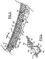
- FIG. 1 and 3 part of a vehicle automobile 10 comprising a windshield 12 whose lower edge 14 is fitted with a seal which extends above a grid awning 16 which is extended by a sheet 18 partially defining the engine compartment.
- the wiping of the windscreen 12 is ensured by means of example of two opposing wipers 20 of which only one is visible in Figures 1 and 3.
- the wiper 20 comprises, in known manner, an arm wiper 22 which is rotatably mounted about an axis of sweep 24 and it carries, at its free end 26, a broom wiper 28 which is here a reduced height brush, of the type "flat blade".
- the brush 28 mainly consists of a lower wiping blade 30 and by an upper structural element of reinforcement and support 32 of the wiper blade 30.
- the wiping blade 30 is shaped general of reverse arrow and it is delimited by an edge lower free end longitudinal 34 which is intended for cooperate with the outer surface of the windshield 12 to be wiped, when the arm 22 is driven for this purpose in a movement of alternating rotary scanning.
- the reinforcing structural element 32 is presented here under the form of a bar 36 of longitudinal orientation which overlaps the upper heel 38 of the wiper blade 30 and which has two parallel, opposite and coplanar side wings 40 which extend transversely on either side of the body 36.
- a housing is provided fixed 41 comprising an upper frame 42 and a gutter closed internal lower 44 so as to define a housing 46 which, when the wiper is in its parking position shown in Figures 1 and 2, receives the flexible wiping blade 30 in a retracted position.
- the moving element constituted by the wiping blade 30 with its associated structural element 32, 40 which constitutes the flap of closing the open upper face of the housing 46, that is to say the shutter closing the light or window 48 delimited through frame 42.
- the lateral wings 40 of the reinforcing structural element 32 extend transversely beyond the longitudinal edges parallel and opposite 50 of window 48.
- each lateral wing 40 of the element structural 32 is advantageously fitted with a gasket seal 54 which, as can be seen in FIG. 1, extends all around the element 32 and whose lower lips 56 are interposed between the wings 40 and the upper face opposite the corresponding portion of the frame 42.
- advantageous arrangements can be made one or more drainage holes 56 in the bottom of the gutter 44.
- the shutter of closing the well 46 belongs to the wiper blade 28 with which it forms a structural whole and with which it moves in alternating wiping when wiping the windshield.
- the design according to the invention therefore requires no means for controlling the position of the flap as is the case in designs according to the state of the art.
- housing 41 or an equivalent structure delimiting the housing or well 46 can be made molded in a single piece with awning grille 16.
- the dimensioning of the housing 46, and in particular its depth, is such that, in the retracted position of the blade wiping 30 in the well 46 and when the wings 40 are in support against the frame 42, the lower free end edge 34 is distant from the bottom wall facing 45 from the gutter 44.
- the open face or window 48 for retracting the wiper blade 30 is formed by a slot formed directly in the window 12 and which is delimited by two edges parallel and opposite 50 opposite the window.
- the structural element associated with the wiper blade 30 is constituted by its two longitudinal reinforcing vertebrae which extend transversely beyond the body of his heel upper 38 to constitute the wings 40 which come to bear vertical watertight on the portions facing the upper face of the window 12 adjacent to the edges 50.
- the third embodiment shown in Figure 6 is analogous to the second embodiment shown in Figure 5, but the slot 48 is here delimited by an edge 50 of the window 12 and by an edge facing 50 of the grid 16.
- Figure 7 is a fourth analogous embodiment to the previous one in that the slot 48 is formed between an edge 50 of the window 12 and an edge 50 belonging to the grid 16, these two edges 50 each being here equipped with a trim 66.
- These fittings 66 delimit the housing 46 therebetween and which are in elastic support against each other, so as to close the housing in the vicinity of their lower lips 68 between which can be evacuated from the liquid entering the housing 46, with possible other pollutants.
- the slot 48 can also be formed between two edges of the awning grid, between one edge of the awning grid and an edge of the adjacent sheet of the structure of the vehicle, or between two edges of sheet metal belonging to the structure of the vehicle or a body part thereof.
- the fifth embodiment shown in Figure 8 is analogous to the previous one in its general conception to with the exception of fittings 66 which here include means 70 providing thermal regulation inside the housing 46.
- the lateral faces of the linings 66 can thus be configured as radiators 72 while they may also include heating elements 74.
- the heating elements 74 can for example be constituted by devices using the Pelletier effect for heating or cooling the housing 46.
- One such treatment consists in putting the active surfaces of the blade 30 in contact with a product, in the form of liquid or a gel, used to regenerate the material constituting the blade or deposit treatment products on its surfaces of surface.
- moisturizers can for example be moisturizers or a halogenation product.
- the treatment product may be a liquid contained in the bottom of the housing 46 which then constitutes a treatment bath.
- the treatment product can also be in the form of a gel contained in housing 46.
- this membrane By injecting air under the membrane 74, for example by orifices 76, this membrane can be "inflated", so that that it is deployed in the housing 46.
- the swelling of the limb 74 can be complete and it then constitutes a means of closing the housing 46 so prevent it from filling up with liquid and / or elements pollutants during the operation of the wiper.
- the membrane 74 will then perform a deposition of the gel on the side faces opposite and on the edge free end 34 of the wiper blade 30.
- the swelling of the membrane can also be used, when starting the wiper, to push the wiper blade 30 outside accommodation 46.
- the housing 46 is formed in a housing 41 which is itself a movable mounted element in rotation relative to a fixed element 80 of the vehicle structure, adjacent to the window 12, and this around an axis of rotation A1 parallel to the general longitudinal direction of the housing 46.
- the housing 41 has a peripheral wall convex tubular 82 which is rotatably mounted in a wall concave cylindrical complementary 84 to the fixed element 80.
- the tubular wall 82 is incomplete and it is extended by a gutter-shaped part 44 of U-shaped section which internally delimits the housing 46.
- the concave semi-cylindrical wall 80 extends over a semicircle and it is thus opened vertically upwards so as to allow on the one hand the mounting of the housing 41 and, on the other hand, to give access to the part of the latter which makes protruding upwards beyond the plane of the planar upper face 88 of the element 80 adjacent to the semi-cylindrical tubular wall 84.
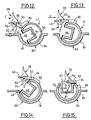
- the housing 41 is thus pivotally mounted between its position extreme rest, shown in Figure 12, towards which it can to be recalled elastically and that is defined by means of stop not shown in the figures.
- the housing 41 In this angular position, which is here offset angularly around 135 ° relative to the rest position, the housing 41 is in an active position in which it can receive the wiper blade 30 and in which the upper face open 48 of the housing 46 is oriented vertically towards the high.
- the wiper blade 28 has a control finger 90 which comprises a radial branch 92 mounted articulated around a longitudinal axis A2, between two extreme positions, which is extends by a longitudinal branch 94 parallel to the axis and which, when the squeegee 28 cooperates with the housing 41 in the form of drum, extends opposite it.
- the finger 90 by its axial orientation branch 94, is capable of cooperating with a lug 96 formed opposite on the outer face of the tubular wall 82 of the housing 41 and which is arranged longitudinally to the right of the control finger 90.
- control finger 90 When the wiper approaches its parking position, as shown in figure 12, the control finger 90 is in its low angular position around the axis A2 and its axial branch 94 abuts against the face opposite the lug 96.
- the brush 28 moves generally according to the horizontal arrow F in FIG. 12 and the finger 90-94 thus rotates the housing 41, about the axis A1, clockwise considering Figure 12.
- the finger 90, 94 pivots about its axis A2 to reach its other extreme angular position in which it is substantially horizontal.
- the branch 94 continues to push the lug 96 to drive gradually the housing 41 to its active position shown in Figure 15.
- the wiping blade 30 gradually enters the housing 46 as and measurement of the progress of the blade 30 according to arrow F and therefore as the clockwise rotation of the housing 41 around the axis A1.
- the wiper blade 30, as shown in FIG. 15, is fully retracted into the housing 46 and the wings 40 constitute the closing flap of the open upper face of the housing 46.
- the lug 96 serves as a stop to define the angular position active of the housing 41 which is maintained in this position due to the presence of the wiper blade 30 which exerts pressure and friction preventing a return of the housing 41 to its rest position illustrated in figure 12.
- the wiper blade 30 is driven horizontally from right to left starting from Figure 15 and the blade 30 drives the housing 41 counterclockwise around its axis A1, movement in which he is accompanied by his means of elastic reminder.
- the invention is not limited to a wiper blade of the "flat-blade” type but it can also be applied in the case of a broom in the form of a structure hinged classic using articulated support stirrups of the blade, the flap part can for example be formed by lateral extensions of the vertebrae of reinforcement to which the stirrups are fixed by claws.
Landscapes
- Engineering & Computer Science (AREA)
- Mechanical Engineering (AREA)
- Chemical & Material Sciences (AREA)
- Combustion & Propulsion (AREA)
- Transportation (AREA)
- Body Structure For Vehicles (AREA)
Abstract
Description
- le volet est constitué au moins en partie par l'élément structurel associé à la lame d'essuyage ;
- la face ouverte du logement est délimitée latéralement par deux bords parallèles et opposés, et le volet comporte deux ailes latérales parallèles et opposées qui, en position escamotée de la lame d'essuyage s'étendent transversalement chacune au-dessus et au delà du bord correspondant de la face ouverte du logement, avec interposition de moyens d'étanchéité ;
- les moyens d'étanchéité sont portés par le volet ;
- la face ouverte du logement est une fente délimitée par deux bords parallèles opposés ;
- la fente est délimitée par deux bords opposés en vis-à-vis appartenant chacun à un élément de structure ou de carrosserie du véhicule ;
- la fente est formée dans la vitre à essuyer ;
- la fente est délimitée par un bord de la vitre et par un bord d'un élément de structure ou de carrosserie du véhicule ;
- chaque bord de la fente est muni d'une garniture ;
- le logement comporte des moyens de régulation de la température et/ou de l'hygrométrie à l'intérieur du logement ;
- le logement comporte des moyens de traitement physique et/ou chimique de la lame d'essuyage en position escamotée ;
- lesdits moyens de traitement comportent des moyens d'aspersion de la lame d'essuyage avec un liquide, un gel ou une poudre de traitement ;
- lesdits moyens de traitement comportent un gel ou un liquide de traitement contenu dans le logement pour constituer un bain de traitement de la lame d'essuyage ;
- les moyens de traitement comportent un élément, notamment une membrane gonflable, revêtu d'un liquide ou d'un gel de traitement et qui est susceptible de se déplacer pour venir au contact de la lame d'essuyage en position escamotée ;
- le logement comporte des moyens de surveillance optique de l'état de la lame d'essuyage en position escamotée ;
- l'agencement comporte des moyens de fermeture de la face ouverte du logement lorsque la lame d'essuyage n'est pas escamotée dans le logement ;
- les moyens de fermeture comportent une membrane gonflable ;
- le logement est formé dans un boítier qui est monté pivotant, par rapport à la structure du véhicule et autour d'un axe parallèle à la direction longitudinale du logement, entre une position extrême de repos qu'il occupe lorsque l'essuie-glace est en fonctionnement et dans laquelle la face ouverte du logement est masquée, et une position active qu'il occupe lorsque l'essuie-glace est dans sa position de parking et dans laquelle la face ouverte du logement est orientée pour permettre à la lame d'essuyage d'être reçue en position escamotée dans le logement ;
- des moyens de commande du pivotement du boítier vers sa position active comportent un ergot de commande avec lequel l'essuie-glace est susceptible de coopérer lorsqu'il approche de sa position de parking ;
- le boítier est rappelé élastiquement vers sa position de repos ;
- la lame d'essuyage comporte une vertèbre de renfort qui coopère avec l'ergot.
- la figure 1 est une vue schématique en perspective de la partie avant d'un véhicule automobile dont le pare-brise est équipé d'un dispositif d'essuyage à balayage rotatif alterné qui est réalisé conformément aux enseignements de l'invention ;
- la figure 2 est une vue schématique en section transversale selon la ligne 2-2 de la figure 1 et sur laquelle, comme à la figure 1, l'essuie-glace est en position de parking et la lame d'essuyage est représentée en position escamotée dans son logement ;
- les figures 3 et 4 sont des vues similaires à celle des figures 1 et 2 sur lesquelles l'essuie-glace est dans une position d'essuyage du pare-brise ;
- les figures 5 à 9 sont des vues schématiques en section similaires à celle de la figure 2 qui illustrent des différents modes de réalisation de l'invention analogues au premier mode de réalisation représenté aux figures 1 à 4 dans lesquelles le logement ou puits qui reçoit la lame d'essuyage en position escamotée est formé dans une partie fixe du véhicule ;
- la figure 10 est une vue de détail en perspective qui illustre un autre mode de réalisation d'un dispositif d'essuyage conforme aux enseignements de l'invention dans lequel le logement est formé dans un boítier monté rotatif par rapport à la structure du véhicule ;
- la figure 11 est une vue de détail en perspective du mode de réalisation représenté à la figure 10 dans lequel la lame d'essuyage est représentée lors de sa phase d'approche du boítier ; et
- les figures 12 à 15 sont des vues schématiques en section transversale qui représentent l'agencement des figures 10 à 11 dans quatre positions relatives de la lame d'essuyage et du boítier comportant le logement pour la lame d'essuyage, qui sont quatre positions angulaires successives, depuis la position d'approche de la figure 12 jusqu'à la position escamotée de la lame d'essuyage de la figure 15.
Claims (21)
- Agencement d'un dispositif d'essuie-glace pour l'essuyage d'une vitre (12) de véhicule automobile, notamment d'un pare-brise, du type comportant au moins un essuie-glace (20), animé d'un mouvement de balayage alterné de la vitre, qui comporte notamment une lame souple (30) d'essuyage de la vitre qui est associée à au moins un élément structurel (32) qui s'étend au-dessus de la lame d'essuyage, et du type dans lequel l'essuie-glace est susceptible d'occuper une position de parking dans laquelle au moins la lame d'essuyage (30) est escamotée dans un logement (46) de forme générale allongée selon la direction générale de la lame et qui comporte une face supérieure ouverte (48) par laquelle la lame d'essuyage (30) est susceptible de pénétrer dans le logement (46) lorsque l'essuie glace atteint sa position de parking, et du type comportant un volet (40) de fermeture du logement (46) qui est monté mobile entre une position ouverte dans laquelle la face ouverte (48) du logement est dégagée, et une position fermée dans laquelle le volet (40) obture le logement à l'intérieur duquel la lame d'essuyage (30) est escamotée,
caractérisé en ce que le volet constitue un équipage mobile avec la lame d'essuyage (30). - Agencement selon la revendication précédente, caractérisé en ce que le volet (40) est constitué au moins en partie par l'élément structurel (32) associé à la lame d'essuyage.
- Agencement selon l'une quelconque des revendications précédentes, caractérisé en ce que la face ouverte (48) du logement (46) est délimitée latéralement par deux bords (50) parallèles et opposés, et en ce que le volet comporte deux ailes latérales (40) parallèles et opposées qui, en position escamotée de la lame d'essuyage (30), s'étendent transversalement chacune au-dessus et au-dela du bord correspondant (50) de la face ouverte (48) du logement (46), avec interposition de moyens d'étanchéité (54, 56).
- Agencement selon la revendication précédente, caractérisé en ce que les moyens d'étanchéité (54, 56) sont portés par le volet (40).
- Agencement selon l'une quelconque des revendications précédentes, caractérisé en ce que la face ouverte (48) du logement est une fente délimitée par deux bords parallèles opposés (50).
- Agencement selon la revendication 5, caractérisé en ce que la fente (48) est délimitée par deux bords opposés (50) en vis-à-vis appartenant chacun à un élément de structure (16, 18) ou de carrosserie du véhicule.
- Agencement selon la revendication 5, caractérisé en ce que la fente (48) est formée dans la vitre à essuyer (12).
- Agencement selon la revendication 5, caractérisé en ce que la fente (48) est délimitée par un bord (50) de la vitre (12) et par un bord (50) d'un élément de structure (16,18) ou de carrosserie du véhicule.
- Agencement selon l'une quelconque des revendications 5 à 8, caractérisé en ce que chaque bord (50) de la fente est muni d'une garniture (66).
- Agencement selon l'une quelconque des revendications précédentes, caractérisé en ce que le logement (46) comporte des moyens de régulation (70, 72, 74) de la température et/ou de l'hygrométrie à l'intérieur du logement (46).
- Agencement selon l'une quelconque des revendications précédentes, caractérisé en ce que le logement (46) comporte des moyens de traitement physique et/ou chimique de la lame d'essuyage (30) en position escamotée.
- Agencement selon la revendication précédente, caractérisé en ce que lesdits moyens de traitement comportent des moyens d'aspersion de la lame d'essuyage (30) avec un liquide, un gel ou une poudre de traitement.
- Agencement selon la revendication 11, caractérisé en ce que lesdits moyens de traitement comportent un gel ou un liquide de traitement contenu dans le logement pour constituer un bain de traitement de la lame d'essuyage.
- Agencement selon la revendication 11, caractérisé en ce que les moyens de traitement comportent un élément, notamment une membrane gonflable (75), revêtu d'un liquide ou d'un gel de traitement et qui est susceptible de se déplacer pour venir au contact de la lame d'essuyage (30) en position escamotée.
- Agencement selon l'une quelconque des revendications précédentes, caractérisé en ce que le logement (46) comporte des moyens de surveillance optique de l'état de la lame d'essuyage (30) en position escamotée.
- Agencement selon l'une quelconque des revendications précédentes, caractérisé en ce qu'il comporte des moyens (75, 41) de fermeture de la face ouverte (48) du logement (46) lorsque la lame d'essuyage (30) n'est pas escamotée dans le logement (46).
- Agencement selon la revendication précédente, caractérisé en ce que les moyens de fermeture comportent une membrane gonflable (75).
- Agencement selon la revendication précédente, caractérisé en ce que le logement (46) est formé dans un boítier (41) qui est monté pivotant, par rapport à la structure du véhicule et autour d'un axe (A1) parallèle à la direction longitudinale du logement, entre une position extrême de repos qu'il occupe lorsque l'essuie-glace est en fonctionnement et dans laquelle la face ouverte (48) du logement (46) est masquée, et une position active qu'il occupe lorsque l'essuie-glace est dans sa position de parking et dans laquelle la face ouverte (48) du logement (46) est orientée pour permettre à la lame d'essuyage d'être reçue en position escamotée dans le logement.
- Agencement selon la revendication précédente, caractérisé en ce que des moyens de commande du pivotement du boítier (41) vers sa position active comportent un ergot (96) de commande avec lequel l'essuie-glace (90, 94) est susceptible de coopérer lorsqu'il approche de sa position de parking.
- Agencement selon l'une des revendications 18 ou 19, caractérisé en ce que le boítier (41) est rappelé élastiquement vers sa position de repos.
- Agencement selon qu'une quelconque des revendications 18 à 20, caractérisé en ce que la lame d'essuyage (30) comporte une vertèbre de renfort qui coopère avec l'ergot.
Applications Claiming Priority (2)
| Application Number | Priority Date | Filing Date | Title |
|---|---|---|---|
| FR0011580A FR2813834B1 (fr) | 2000-09-12 | 2000-09-12 | Agencement d'essuie-glace comportant des moyens de protection de la lame d'essuyage en position de parking |
| FR0011580 | 2000-09-12 |
Publications (1)
| Publication Number | Publication Date |
|---|---|
| EP1186492A1 true EP1186492A1 (fr) | 2002-03-13 |
Family
ID=8854187
Family Applications (1)
| Application Number | Title | Priority Date | Filing Date |
|---|---|---|---|
| EP01203425A Withdrawn EP1186492A1 (fr) | 2000-09-12 | 2001-09-12 | Agencement d'essuie-glace comportant des moyens de protection de la lame d'essuyage en position de parking. |
Country Status (2)
| Country | Link |
|---|---|
| EP (1) | EP1186492A1 (fr) |
| FR (1) | FR2813834B1 (fr) |
Cited By (4)
| Publication number | Priority date | Publication date | Assignee | Title |
|---|---|---|---|---|
| FR2863233A1 (fr) * | 2003-12-08 | 2005-06-10 | Valeo Systemes Dessuyage | Module d'essuyage comportant un logement de protection du balai d'essuyage |
| EP1743807A1 (fr) * | 2005-07-14 | 2007-01-17 | Möllertech Orense, S.L. | Système d'isolation pour le compartiment moteur basé sur un composant fait de plusieurs matériaux |
| FR2949408A1 (fr) * | 2009-09-01 | 2011-03-04 | Airbus Operations Sas | Essuie-glace escamotable pour vehicule |
| EP4434823A1 (fr) * | 2023-03-22 | 2024-09-25 | Apple Inc. | Système de nettoyage |
Citations (7)
| Publication number | Priority date | Publication date | Assignee | Title |
|---|---|---|---|---|
| GB721465A (en) * | 1952-01-21 | 1955-01-05 | Trico Folberth Ltd | A stowage arrangement for windscreen wipers |
| US2895157A (en) * | 1955-07-13 | 1959-07-21 | Robert J Kocourek | Wiper mechanism |
| US3213478A (en) | 1964-01-27 | 1965-10-26 | Gen Motors Corp | Windshield wiper mechanism |
| US3601839A (en) | 1968-08-12 | 1971-08-31 | Nippon Denso Co | Windshield wiper apparatus |
| DE4219189C1 (en) * | 1992-06-12 | 1993-06-24 | Mercedes-Benz Aktiengesellschaft, 7000 Stuttgart, De | Cleaning system for windscreen wiper - has elastic roller moved under wiper blade in parked position |
| DE4314435A1 (de) * | 1993-05-03 | 1994-11-10 | Steffen Patze | Versenkbare Scheiben-Wisch-und-Wasch-Anlage |
| DE29708554U1 (de) * | 1997-05-14 | 1997-07-10 | Thau, Barbara, 58285 Gevelsberg | Gehäuse für Heckscheibenwischer |
-
2000
- 2000-09-12 FR FR0011580A patent/FR2813834B1/fr not_active Expired - Lifetime
-
2001
- 2001-09-12 EP EP01203425A patent/EP1186492A1/fr not_active Withdrawn
Patent Citations (7)
| Publication number | Priority date | Publication date | Assignee | Title |
|---|---|---|---|---|
| GB721465A (en) * | 1952-01-21 | 1955-01-05 | Trico Folberth Ltd | A stowage arrangement for windscreen wipers |
| US2895157A (en) * | 1955-07-13 | 1959-07-21 | Robert J Kocourek | Wiper mechanism |
| US3213478A (en) | 1964-01-27 | 1965-10-26 | Gen Motors Corp | Windshield wiper mechanism |
| US3601839A (en) | 1968-08-12 | 1971-08-31 | Nippon Denso Co | Windshield wiper apparatus |
| DE4219189C1 (en) * | 1992-06-12 | 1993-06-24 | Mercedes-Benz Aktiengesellschaft, 7000 Stuttgart, De | Cleaning system for windscreen wiper - has elastic roller moved under wiper blade in parked position |
| DE4314435A1 (de) * | 1993-05-03 | 1994-11-10 | Steffen Patze | Versenkbare Scheiben-Wisch-und-Wasch-Anlage |
| DE29708554U1 (de) * | 1997-05-14 | 1997-07-10 | Thau, Barbara, 58285 Gevelsberg | Gehäuse für Heckscheibenwischer |
Cited By (4)
| Publication number | Priority date | Publication date | Assignee | Title |
|---|---|---|---|---|
| FR2863233A1 (fr) * | 2003-12-08 | 2005-06-10 | Valeo Systemes Dessuyage | Module d'essuyage comportant un logement de protection du balai d'essuyage |
| EP1743807A1 (fr) * | 2005-07-14 | 2007-01-17 | Möllertech Orense, S.L. | Système d'isolation pour le compartiment moteur basé sur un composant fait de plusieurs matériaux |
| FR2949408A1 (fr) * | 2009-09-01 | 2011-03-04 | Airbus Operations Sas | Essuie-glace escamotable pour vehicule |
| EP4434823A1 (fr) * | 2023-03-22 | 2024-09-25 | Apple Inc. | Système de nettoyage |
Also Published As
| Publication number | Publication date |
|---|---|
| FR2813834A1 (fr) | 2002-03-15 |
| FR2813834B1 (fr) | 2003-12-05 |
Similar Documents
| Publication | Publication Date | Title |
|---|---|---|
| EP2301785B1 (fr) | Dispositif d'obturation d'une baie ménagée dans le toit d'un véhicule automobile, équipé d'une barrière d'étanchéité et d'une évacuation d'eau vers l'extérieur. | |
| FR3066452B1 (fr) | Dispositif de vision exterieure pour vehicule, comprenant une camera | |
| FR2858280A1 (fr) | Dispositif de vision arriere pour vehicule automobile | |
| FR2728199A1 (fr) | Vehicule equipe d'un toit rigide escamotable | |
| FR2598124A1 (fr) | Systeme de lunette arriere escamotable pour vehicules | |
| EP1186493B1 (fr) | Agencement d'un dispositif d'essuie-glace | |
| FR2813834A1 (fr) | Agencement d'essuie-glace comportant des moyens de protection de la lame d'essuyage en position de parking | |
| EP2598357B1 (fr) | Dispositif d'obturation d'une baie menagee dans le toit d'un vehicule automobile, apte a etre place dans une position d'obturation partielle | |
| FR2807714A1 (fr) | Systeme de toit ouvrant pour vehicule decouvrable | |
| EP0791514B1 (fr) | Essuie-glace de véhicule automobile muni d'un capot d'habillage comportant un tronçon d'extrémité | |
| EP1006013B1 (fr) | Dispositif formant toit coulissant de véhicule automobile | |
| EP2694306B2 (fr) | Pavillon vitre a panneau mobile coulissant et entrebaillant | |
| FR2943303A1 (fr) | Partie avant de vehicule automobile | |
| FR2746750A1 (fr) | Essuie-glace de vehicule automobile comportant une canalisation d'alimentation dissimulee sous un capot d'habillage | |
| EP1571068B1 (fr) | Dispositif pour cacher et proteger les balais d'essuie-glace d'un véhicule automobile en position inactive | |
| FR2462311A1 (fr) | Element d'essuie-glace, notamment pour vehicules automobiles | |
| FR2728520A1 (fr) | Dispositif d'essuie-glace de vehicule automobile du type comportant des moyens de protection d'au moins un essuie-glace en position de parking | |
| FR2615835A1 (fr) | Assemblage d'un capot retractable et de guides et capot telescopique pour une structure de stockage | |
| FR2963282A1 (fr) | Dispositif d'obturation d'une baie menagee dans le toit d'un vehicule automobile, apte a etre place dans une position d'obturation partielle | |
| FR2778429A1 (fr) | Trappe de desenfumage pour galerie d'air de tunnel routier | |
| FR2744972A1 (fr) | Essuie-glace de vehicule automobile muni d'un capot d'habillage qui porte un dispositif d'arrosage | |
| FR2920113A1 (fr) | Portiere de vehicule a dispositif d'occultation en partie basse. | |
| EP0498866B1 (fr) | Essuie-glace centralise flexible a aspiration et aspersion integrees | |
| FR2890005A1 (fr) | Vehicule automobile a toit escamotable, notamment de type coupe-cabriolet. | |
| FR2850620A1 (fr) | Balai d'essuie-glace |
Legal Events
| Date | Code | Title | Description |
|---|---|---|---|
| PUAI | Public reference made under article 153(3) epc to a published international application that has entered the european phase |
Free format text: ORIGINAL CODE: 0009012 |
|
| AK | Designated contracting states |
Kind code of ref document: A1 Designated state(s): AT BE CH CY DE DK ES FI FR GB GR IE IT LI LU MC NL PT SE TR Kind code of ref document: A1 Designated state(s): DE ES FR GB IT |
|
| AX | Request for extension of the european patent |
Free format text: AL;LT;LV;MK;RO;SI |
|
| 17P | Request for examination filed |
Effective date: 20020722 |
|
| AKX | Designation fees paid |
Free format text: DE ES FR GB IT |
|
| 17Q | First examination report despatched |
Effective date: 20050624 |
|
| STAA | Information on the status of an ep patent application or granted ep patent |
Free format text: STATUS: THE APPLICATION IS DEEMED TO BE WITHDRAWN |
|
| 18D | Application deemed to be withdrawn |
Effective date: 20060822 |