EP1186456A2 - Schliesskantensicherung - Google Patents
Schliesskantensicherung Download PDFInfo
- Publication number
- EP1186456A2 EP1186456A2 EP01121212A EP01121212A EP1186456A2 EP 1186456 A2 EP1186456 A2 EP 1186456A2 EP 01121212 A EP01121212 A EP 01121212A EP 01121212 A EP01121212 A EP 01121212A EP 1186456 A2 EP1186456 A2 EP 1186456A2
- Authority
- EP
- European Patent Office
- Prior art keywords
- length
- hollow profile
- sensor device
- hollow
- active
- Prior art date
- Legal status (The legal status is an assumption and is not a legal conclusion. Google has not performed a legal analysis and makes no representation as to the accuracy of the status listed.)
- Granted
Links
Images
Classifications
-
- B—PERFORMING OPERATIONS; TRANSPORTING
- B60—VEHICLES IN GENERAL
- B60J—WINDOWS, WINDSCREENS, NON-FIXED ROOFS, DOORS, OR SIMILAR DEVICES FOR VEHICLES; REMOVABLE EXTERNAL PROTECTIVE COVERINGS SPECIALLY ADAPTED FOR VEHICLES
- B60J10/00—Sealing arrangements
-
- E—FIXED CONSTRUCTIONS
- E05—LOCKS; KEYS; WINDOW OR DOOR FITTINGS; SAFES
- E05F—DEVICES FOR MOVING WINGS INTO OPEN OR CLOSED POSITION; CHECKS FOR WINGS; WING FITTINGS NOT OTHERWISE PROVIDED FOR, CONCERNED WITH THE FUNCTIONING OF THE WING
- E05F15/00—Power-operated mechanisms for wings
- E05F15/40—Safety devices, e.g. detection of obstructions or end positions
- E05F15/42—Detection using safety edges
- E05F15/44—Detection using safety edges responsive to changes in electrical conductivity
- E05F15/443—Detection using safety edges responsive to changes in electrical conductivity specially adapted for vehicle windows or roofs
-
- E—FIXED CONSTRUCTIONS
- E05—LOCKS; KEYS; WINDOW OR DOOR FITTINGS; SAFES
- E05Y—INDEXING SCHEME ASSOCIATED WITH SUBCLASSES E05D AND E05F, RELATING TO CONSTRUCTION ELEMENTS, ELECTRIC CONTROL, POWER SUPPLY, POWER SIGNAL OR TRANSMISSION, USER INTERFACES, MOUNTING OR COUPLING, DETAILS, ACCESSORIES, AUXILIARY OPERATIONS NOT OTHERWISE PROVIDED FOR, APPLICATION THEREOF
- E05Y2900/00—Application of doors, windows, wings or fittings thereof
- E05Y2900/50—Application of doors, windows, wings or fittings thereof for vehicles
- E05Y2900/53—Type of wing
- E05Y2900/55—Windows
Definitions
- the invention relates to a closing edge safety device for a movable Locking part on a motor vehicle with an elastic hollow profile, the longitudinal an edge area of a cutout that can be closed by the closing part is arranged, and the at least one hollow chamber for receiving a elongated sensor device for an active security area of the Has hollow profile, the length of the active securing area for the Closing part is less than the length of the hollow profile.
- DE 43 28 167 C2 is a closing edge safety device for a known electromotive movable side window of a motor vehicle, at a hollow chamber is provided in a disc sealing profile, into which one electrical contact strip assembly is retracted.
- Closing edge safety corresponds to the length of the contact strip arrangement, i.e. the sensor device, the length of the window sealing profile.
- the object of the invention is to secure the closing edge at the beginning to create a safe function with reduced effort having.
- the longitudinal sensor device is matched to the length of the active safety area, and that with an inactive pull piece at one end of the longitudinal sensor device is permanently connected, which runs in the hollow chamber of the hollow profile and has a length approximately between the length of the hollow chamber section the end of the active safety area and the front end of the Corresponds to the hollow profile on the side provided with the inactive tension piece.
- the solution according to the invention is based on the knowledge that a safe Function of the closing edge safety device is also ensured that the sensor device only over the length of the active Security area extends. As a result, the sensor device can be compared a reduced sensor device known from the prior art Have length, which means the cost compared to a known Closing edge safety is significantly reduced.
- the longitudinally extended sensor device reliably to be able to pull in the hollow profile, and secondly, to guarantee can that the sensor device actually within the hollow profile is aligned that it extends the entire length of the active Security area extends.
- the inactive pull piece has the advantage that it is simple Traction element executed without sensory or electrical properties can be.
- the traction piece can be a simple band Thread or the like.
- the solution according to the invention is particularly suitable for Closing edge safety devices on the side windows of motor vehicles.
- the closing edge safety device is also suitable for sunroofs, doors and flaps or bonnets can be used.
- a drive in particular a electric motor drive.
- the closing edge safety device prevents that the locking part is transferred to its closed position when an object in the space between the corresponding front edge of the Locking part and the surrounding body section of the motor vehicle located.
- the pull piece protrudes from the front end front end of the hollow profile, and at the front end is a Fasteners provided.
- the pull piece is therefore slightly longer than the length of the cavity section between the end of the active Security area and the rear end of the hollow profile - in Seen feed direction.
- the length of the pull piece always corresponds still approximately the length of this hollow chamber section.
- the minor, about the length of this hollow chamber section extending length section of Tension piece corresponds to the length of the fastener. Because only that Fastener protrudes beyond the front end of the hollow profile.
- Fasteners can be a separate fastener with the tension piece be connected. It can also be provided in the front of the Switzerland Federationes integrally integrate a fastener.
- a preferred Integrated fastener is one made from the material of the tension piece formed loop.
- the fastener makes it possible to Connection with a body-side fastener, the pull and thus also to fix the sensor device in the correct position. A Displacement of the sensor device against the direction of pull is thereby avoided.
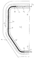
- the only drawing shows schematically in one Sectional view of an embodiment of a Closing edge safety device according to the invention in the edge area a window cutout for a side window Motor vehicle.
- a side door 1 of a passenger car only partially shown has a window section 2, which is shown by a not shown, electromotive movable side window is closable.
- the edge area of the window cutout 2 is by a circumferential elastic hollow profile 3 documented, which is attached to this edge area in a generally known manner and serves as a window guide.
- the elastic hollow profile 3 has a Entire length of the elastic hollow profile 3 continuous hollow chamber 4th in which a sensor device 5 is drawn.
- the sensor device 5 is in particular according to a contact strip arrangement according to DE 42 28 167 C2 designs and has a length that is less than the stretched length the hollow chamber and the hollow profile 3.
- the hollow profile 3 points to Closing edge safety device in an upper area of the window cutout 2, in which the edge area of the window section as well as the guidance of the Hollow profile 3 deviates from the vertical orientation, an active Security area 12 on, which is from the left in the drawing starting line 11 extends to the right end line 13 in the drawing.
- an active Security area 12 In this active Security area 12 must be reliable, safe and consistent Function of the sensor device 5 can be guaranteed.
- the sensor device 5 is from a front End 10 of the hollow profile 3 drawn into the hollow chamber 4, wherein a Appropriate retraction tool from a rear end 14 in the Corresponding front end of the hollow profile 4 inserted and through this End 14 is gradually pulled down.
- the front side of the sensor device 5 is a inactive pull piece 8 attached inseparably, which via a coupling member 7, for example in the form of a pull loop, fixed to the front end of the Sensor device 5 is connected.
- the length of the inactive traction piece 8 corresponds to either identical or in a tolerance range of +5 to + 15mm the length of the hollow chamber section between the end line 13 and the rear end face 14 of the hollow profile 3.
- At one - in the feed direction seen - front end of the inactive pull piece 8 has a drawbar eye or Pull loop 9 to allow the pulling tool to attack.
- the Sensor device 5 is thus easily inserted into hollow chamber 4 of the hollow profile 3 retracted until the front pull loop 9 of the inactive Tension piece 8 by a small amount from the rear end 14 of the Hollow profile 3 or the hollow chamber 4 protrudes. Because the length of the inactive Pull piece 8 to the length of the inactive hollow chamber section between the end line 13 and the front end 14 is matched by reaching of the rear end 14 pull loop 9 ensures that the Sensor device 5 is correctly positioned in the security area 12. In On the back of the feed direction, connecting cables 6 protrude to the front end 10 of the hollow profile down to the electrical connection with a to create appropriate switching arrangement.
Landscapes
- Engineering & Computer Science (AREA)
- Mechanical Engineering (AREA)
- Power-Operated Mechanisms For Wings (AREA)
- Lock And Its Accessories (AREA)
- Window Of Vehicle (AREA)
- Temperature-Responsive Valves (AREA)
- Glass Compositions (AREA)
Abstract
Einsatz für Schließkantensicherungen an Seitenscheiben von Kraftfahrzeugen.
Description
Claims (3)
- Schließkantensicherung für ein bewegliches Schließteil an einem Kraftfahrzeug mit einem elastischen Hohlprofil, das längs eines Randbereiches eines durch das Schließteil verschließbaren Ausschnittes angeordnet ist, und das wenigstens eine Hohlkammer zur Aufnahme einer längserstreckten Sensoreinrichtung für einen aktiven Sicherungsbereich des Hohlprofiles aufweist, wobei die Länge des aktiven Sicherungsbereiches für das Schließteil geringer ist als die Länge des Hohlprofiles, dadurch gekennzeichnet, daß die längserstreckte Sensoreinrichtung (5) auf die Länge des aktiven Sicherungsbereiches (12) abgestimmt ist, und daß mit einem Ende der längserstreckten Sensoreinrichtung (5) ein inaktives Zugstück (8) permanent verbunden ist, das in der Hohlkammer (4) des Hohlprofiles (3) verläuft und eine Länge aufweist, die etwa der Länge des Hohlkammerabschnittes zwischen dem Ende (13) des aktiven Sicherungsbereiches (12) und dem stirnseitigen Ende (14) des Hohlprofiles (3) auf der mit dem inaktiven Zugstück (8) versehenen Seite entspricht.
- Schließkantensicherung nach Anspruch 1, dadurch gekennzeichnet, daß das Zugstück (8) mit einem Stirnende aus dem stirnseitigen Ende (14) des Hohlprofiles (3) herausragt, und daß an dem Stirnende ein Befestigungsmittel vorgesehen ist.
- Schießkantensicherung nach Anspruch 2, dadurch gekennzeichnet, daß als Befestigungsmittel eine Zugschlaufe (9) vorgesehen ist.
Applications Claiming Priority (2)
| Application Number | Priority Date | Filing Date | Title |
|---|---|---|---|
| DE20015330U DE20015330U1 (de) | 2000-09-05 | 2000-09-05 | Schließkantensicherung |
| DE20015330U | 2000-09-05 |
Publications (3)
| Publication Number | Publication Date |
|---|---|
| EP1186456A2 true EP1186456A2 (de) | 2002-03-13 |
| EP1186456A3 EP1186456A3 (de) | 2002-10-09 |
| EP1186456B1 EP1186456B1 (de) | 2006-02-22 |
Family
ID=7946077
Family Applications (1)
| Application Number | Title | Priority Date | Filing Date |
|---|---|---|---|
| EP01121212A Expired - Lifetime EP1186456B1 (de) | 2000-09-05 | 2001-09-05 | Schliesskantensicherung |
Country Status (3)
| Country | Link |
|---|---|
| EP (1) | EP1186456B1 (de) |
| AT (1) | ATE318225T1 (de) |
| DE (2) | DE20015330U1 (de) |
Cited By (3)
| Publication number | Priority date | Publication date | Assignee | Title |
|---|---|---|---|---|
| US8493081B2 (en) | 2009-12-08 | 2013-07-23 | Magna Closures Inc. | Wide activation angle pinch sensor section and sensor hook-on attachment principle |
| US9234979B2 (en) | 2009-12-08 | 2016-01-12 | Magna Closures Inc. | Wide activation angle pinch sensor section |
| WO2022197202A1 (ru) | 2021-03-18 | 2022-09-22 | Дмитрий Викторович САВЕЛЬЕВ | Контейнер |
Family Cites Families (3)
| Publication number | Priority date | Publication date | Assignee | Title |
|---|---|---|---|---|
| DE19602744C2 (de) * | 1996-01-19 | 1999-04-29 | Mayser Gmbh & Co | Sicherheitsschaltleistenanordnung |
| DE19825297C2 (de) * | 1998-06-05 | 2000-06-21 | Metzeler Automotive Profiles | Profilrahmen für eine kraftbetätigte Schließeinrichtung |
| JP2000226966A (ja) * | 1999-02-05 | 2000-08-15 | Harness Syst Tech Res Ltd | 挟込み検出装置 |
-
2000
- 2000-09-05 DE DE20015330U patent/DE20015330U1/de not_active Expired - Lifetime
-
2001
- 2001-09-05 AT AT01121212T patent/ATE318225T1/de not_active IP Right Cessation
- 2001-09-05 DE DE50108981T patent/DE50108981D1/de not_active Expired - Fee Related
- 2001-09-05 EP EP01121212A patent/EP1186456B1/de not_active Expired - Lifetime
Cited By (4)
| Publication number | Priority date | Publication date | Assignee | Title |
|---|---|---|---|---|
| US8493081B2 (en) | 2009-12-08 | 2013-07-23 | Magna Closures Inc. | Wide activation angle pinch sensor section and sensor hook-on attachment principle |
| US9234979B2 (en) | 2009-12-08 | 2016-01-12 | Magna Closures Inc. | Wide activation angle pinch sensor section |
| US9417099B2 (en) | 2009-12-08 | 2016-08-16 | Magna Closures Inc. | Wide activation angle pinch sensor section |
| WO2022197202A1 (ru) | 2021-03-18 | 2022-09-22 | Дмитрий Викторович САВЕЛЬЕВ | Контейнер |
Also Published As
| Publication number | Publication date |
|---|---|
| DE50108981D1 (de) | 2006-04-27 |
| EP1186456B1 (de) | 2006-02-22 |
| EP1186456A3 (de) | 2002-10-09 |
| DE20015330U1 (de) | 2001-02-15 |
| ATE318225T1 (de) | 2006-03-15 |
Similar Documents
| Publication | Publication Date | Title |
|---|---|---|
| EP1182104A2 (de) | Vorrichtung zur Verriegelung der Lenkspindel eines Fahrzeuges | |
| DE102011117798B4 (de) | Sicherheitseinrichtung für ein Fahrzeug | |
| DE202014106158U1 (de) | Schließhilfsantrieb für ein Kraftfahrzeugschloss | |
| DE19837662C2 (de) | Türinnenöffnungssystem für eine Fahrzeugtür sowie zugehörige Fahrzeugtür und Montageverfahren | |
| DE2714280A1 (de) | Beruehrungssensitive steuereinrichtung fuer fahrzeugtueren | |
| DE102011113207A1 (de) | Fahrzeugrolloanordnung und Dachanordnung | |
| DE102009031120A1 (de) | Airbageinrichtung für ein Kraftfahrzeug | |
| DE29921859U1 (de) | Seitenfensterrollo | |
| EP1186456B1 (de) | Schliesskantensicherung | |
| DE102017107055A1 (de) | Gleitverbindungsapplikation | |
| DE102023109208B4 (de) | Seitlicher Heckbereich eines Kraftfahrzeugs mit einer Luftleitvorrichtung und Kraftfahrzeug | |
| DE3503806C2 (de) | ||
| DE10259481A1 (de) | Verbindungsanordnung einer Wischvorrichtung für Scheiben von Kraftfahrzeugen | |
| DE102019100986A1 (de) | Schließeinrichtung, Bowdenzug und Verfahren zur Bowdenzugmontage | |
| DE29914588U1 (de) | Vorrichtung zum Bewegen einer Gardine | |
| EP2628877B1 (de) | Montagebaugruppe zur Montage einer Verriegelungseinrichtung | |
| DE2317039C3 (de) | Scharniergelenk für Fenster, Türen o.dgl. | |
| DE102012112033B4 (de) | Verdeckanordnung für ein Kraftfahrzeug | |
| DE102009033129B4 (de) | Vorrichtung zur Anbringung eines Verkleidungsteils an einem Karosserieteil eines Kraftfahrzeugs | |
| DE102004034144B4 (de) | Mitnehmer zur Befestigung einer Fensterscheibe eines Kraftfahrzeuges an einer Führungseinrichtung eines Fensterhebers | |
| DE102010004252B4 (de) | Fensteröffnungssystem | |
| DE10235608B4 (de) | Zuziehvorrichtung | |
| WO2020212070A1 (de) | Flügelelementöffnungsvorrichtung sowie fahrzeug | |
| DE102023124773B4 (de) | Antriebsstrang | |
| DE102006013085B3 (de) | Lenksäulenbaueinheit |
Legal Events
| Date | Code | Title | Description |
|---|---|---|---|
| PUAI | Public reference made under article 153(3) epc to a published international application that has entered the european phase |
Free format text: ORIGINAL CODE: 0009012 |
|
| AK | Designated contracting states |
Kind code of ref document: A2 Designated state(s): AT BE CH CY DE DK ES FI FR GB GR IE IT LI LU MC NL PT SE TR |
|
| AX | Request for extension of the european patent |
Free format text: AL;LT;LV;MK;RO;SI |
|
| PUAL | Search report despatched |
Free format text: ORIGINAL CODE: 0009013 |
|
| RIC1 | Information provided on ipc code assigned before grant |
Free format text: 7B 60J 10/04 A, 7E 05F 15/00 B |
|
| AK | Designated contracting states |
Kind code of ref document: A3 Designated state(s): AT BE CH CY DE DK ES FI FR GB GR IE IT LI LU MC NL PT SE TR |
|
| AX | Request for extension of the european patent |
Free format text: AL;LT;LV;MK;RO;SI |
|
| 17P | Request for examination filed |
Effective date: 20030327 |
|
| AKX | Designation fees paid |
Designated state(s): AT BE CH CY DE DK ES FI FR GB GR IE IT LI LU MC NL PT SE TR |
|
| GRAP | Despatch of communication of intention to grant a patent |
Free format text: ORIGINAL CODE: EPIDOSNIGR1 |
|
| GRAS | Grant fee paid |
Free format text: ORIGINAL CODE: EPIDOSNIGR3 |
|
| GRAA | (expected) grant |
Free format text: ORIGINAL CODE: 0009210 |
|
| AK | Designated contracting states |
Kind code of ref document: B1 Designated state(s): AT BE CH CY DE DK ES FI FR GB GR IE IT LI LU MC NL PT SE TR |
|
| PG25 | Lapsed in a contracting state [announced via postgrant information from national office to epo] |
Ref country code: NL Free format text: LAPSE BECAUSE OF FAILURE TO SUBMIT A TRANSLATION OF THE DESCRIPTION OR TO PAY THE FEE WITHIN THE PRESCRIBED TIME-LIMIT Effective date: 20060222 Ref country code: IE Free format text: LAPSE BECAUSE OF FAILURE TO SUBMIT A TRANSLATION OF THE DESCRIPTION OR TO PAY THE FEE WITHIN THE PRESCRIBED TIME-LIMIT Effective date: 20060222 Ref country code: FI Free format text: LAPSE BECAUSE OF FAILURE TO SUBMIT A TRANSLATION OF THE DESCRIPTION OR TO PAY THE FEE WITHIN THE PRESCRIBED TIME-LIMIT Effective date: 20060222 Ref country code: GB Free format text: LAPSE BECAUSE OF FAILURE TO SUBMIT A TRANSLATION OF THE DESCRIPTION OR TO PAY THE FEE WITHIN THE PRESCRIBED TIME-LIMIT Effective date: 20060222 |
|
| REG | Reference to a national code |
Ref country code: GB Ref legal event code: FG4D Free format text: NOT ENGLISH |
|
| REG | Reference to a national code |
Ref country code: CH Ref legal event code: EP |
|
| REG | Reference to a national code |
Ref country code: IE Ref legal event code: FG4D Free format text: LANGUAGE OF EP DOCUMENT: GERMAN |
|
| REF | Corresponds to: |
Ref document number: 50108981 Country of ref document: DE Date of ref document: 20060427 Kind code of ref document: P |
|
| PG25 | Lapsed in a contracting state [announced via postgrant information from national office to epo] |
Ref country code: SE Free format text: LAPSE BECAUSE OF FAILURE TO SUBMIT A TRANSLATION OF THE DESCRIPTION OR TO PAY THE FEE WITHIN THE PRESCRIBED TIME-LIMIT Effective date: 20060522 Ref country code: DK Free format text: LAPSE BECAUSE OF FAILURE TO SUBMIT A TRANSLATION OF THE DESCRIPTION OR TO PAY THE FEE WITHIN THE PRESCRIBED TIME-LIMIT Effective date: 20060522 |
|
| PG25 | Lapsed in a contracting state [announced via postgrant information from national office to epo] |
Ref country code: ES Free format text: LAPSE BECAUSE OF FAILURE TO SUBMIT A TRANSLATION OF THE DESCRIPTION OR TO PAY THE FEE WITHIN THE PRESCRIBED TIME-LIMIT Effective date: 20060602 |
|
| PG25 | Lapsed in a contracting state [announced via postgrant information from national office to epo] |
Ref country code: PT Free format text: LAPSE BECAUSE OF FAILURE TO SUBMIT A TRANSLATION OF THE DESCRIPTION OR TO PAY THE FEE WITHIN THE PRESCRIBED TIME-LIMIT Effective date: 20060724 |
|
| NLV1 | Nl: lapsed or annulled due to failure to fulfill the requirements of art. 29p and 29m of the patents act | ||
| GBV | Gb: ep patent (uk) treated as always having been void in accordance with gb section 77(7)/1977 [no translation filed] |
Effective date: 20060222 |
|
| REG | Reference to a national code |
Ref country code: IE Ref legal event code: FD4D |
|
| PG25 | Lapsed in a contracting state [announced via postgrant information from national office to epo] |
Ref country code: BE Free format text: LAPSE BECAUSE OF NON-PAYMENT OF DUE FEES Effective date: 20060930 Ref country code: CH Free format text: LAPSE BECAUSE OF NON-PAYMENT OF DUE FEES Effective date: 20060930 Ref country code: LI Free format text: LAPSE BECAUSE OF NON-PAYMENT OF DUE FEES Effective date: 20060930 Ref country code: MC Free format text: LAPSE BECAUSE OF NON-PAYMENT OF DUE FEES Effective date: 20060930 |
|
| ET | Fr: translation filed | ||
| PLBE | No opposition filed within time limit |
Free format text: ORIGINAL CODE: 0009261 |
|
| STAA | Information on the status of an ep patent application or granted ep patent |
Free format text: STATUS: NO OPPOSITION FILED WITHIN TIME LIMIT |
|
| 26N | No opposition filed |
Effective date: 20061123 |
|
| REG | Reference to a national code |
Ref country code: CH Ref legal event code: PL |
|
| PG25 | Lapsed in a contracting state [announced via postgrant information from national office to epo] |
Ref country code: AT Free format text: LAPSE BECAUSE OF NON-PAYMENT OF DUE FEES Effective date: 20060905 |
|
| BERE | Be: lapsed |
Owner name: MAYSER G.M.B.H. & CO. Effective date: 20060930 |
|
| PG25 | Lapsed in a contracting state [announced via postgrant information from national office to epo] |
Ref country code: GR Free format text: LAPSE BECAUSE OF FAILURE TO SUBMIT A TRANSLATION OF THE DESCRIPTION OR TO PAY THE FEE WITHIN THE PRESCRIBED TIME-LIMIT Effective date: 20060523 |
|
| PG25 | Lapsed in a contracting state [announced via postgrant information from national office to epo] |
Ref country code: TR Free format text: LAPSE BECAUSE OF FAILURE TO SUBMIT A TRANSLATION OF THE DESCRIPTION OR TO PAY THE FEE WITHIN THE PRESCRIBED TIME-LIMIT Effective date: 20060222 Ref country code: LU Free format text: LAPSE BECAUSE OF NON-PAYMENT OF DUE FEES Effective date: 20060905 |
|
| PG25 | Lapsed in a contracting state [announced via postgrant information from national office to epo] |
Ref country code: CY Free format text: LAPSE BECAUSE OF FAILURE TO SUBMIT A TRANSLATION OF THE DESCRIPTION OR TO PAY THE FEE WITHIN THE PRESCRIBED TIME-LIMIT Effective date: 20060222 |
|
| PGFP | Annual fee paid to national office [announced via postgrant information from national office to epo] |
Ref country code: FR Payment date: 20080917 Year of fee payment: 8 Ref country code: IT Payment date: 20080925 Year of fee payment: 8 |
|
| PGFP | Annual fee paid to national office [announced via postgrant information from national office to epo] |
Ref country code: DE Payment date: 20081002 Year of fee payment: 8 |
|
| REG | Reference to a national code |
Ref country code: FR Ref legal event code: ST Effective date: 20100531 |
|
| PG25 | Lapsed in a contracting state [announced via postgrant information from national office to epo] |
Ref country code: FR Free format text: LAPSE BECAUSE OF NON-PAYMENT OF DUE FEES Effective date: 20090930 Ref country code: DE Free format text: LAPSE BECAUSE OF NON-PAYMENT OF DUE FEES Effective date: 20100401 |
|
| PG25 | Lapsed in a contracting state [announced via postgrant information from national office to epo] |
Ref country code: IT Free format text: LAPSE BECAUSE OF NON-PAYMENT OF DUE FEES Effective date: 20090905 |