EP1186385A2 - Verfahren und Vorrichtung zur Kalibrierung des Mittelpunkts eines Laserwerkzeuges - Google Patents
Verfahren und Vorrichtung zur Kalibrierung des Mittelpunkts eines Laserwerkzeuges Download PDFInfo
- Publication number
- EP1186385A2 EP1186385A2 EP01121818A EP01121818A EP1186385A2 EP 1186385 A2 EP1186385 A2 EP 1186385A2 EP 01121818 A EP01121818 A EP 01121818A EP 01121818 A EP01121818 A EP 01121818A EP 1186385 A2 EP1186385 A2 EP 1186385A2
- Authority
- EP
- European Patent Office
- Prior art keywords
- aperture
- tool
- aperture assembly
- light
- center point
- Prior art date
- Legal status (The legal status is an assumption and is not a legal conclusion. Google has not performed a legal analysis and makes no representation as to the accuracy of the status listed.)
- Withdrawn
Links
Images



Classifications
-
- G—PHYSICS
- G05—CONTROLLING; REGULATING
- G05B—CONTROL OR REGULATING SYSTEMS IN GENERAL; FUNCTIONAL ELEMENTS OF SUCH SYSTEMS; MONITORING OR TESTING ARRANGEMENTS FOR SUCH SYSTEMS OR ELEMENTS
- G05B19/00—Program-control systems
- G05B19/02—Program-control systems electric
- G05B19/18—Numerical control [NC], i.e. automatically operating machines, in particular machine tools, e.g. in a manufacturing environment, so as to execute positioning, movement or co-ordinated operations by means of program data in numerical form
- G05B19/401—Numerical control [NC], i.e. automatically operating machines, in particular machine tools, e.g. in a manufacturing environment, so as to execute positioning, movement or co-ordinated operations by means of program data in numerical form characterised by control arrangements for measuring, e.g. calibration and initialisation, measuring workpiece for machining purposes
-
- B—PERFORMING OPERATIONS; TRANSPORTING
- B25—HAND TOOLS; PORTABLE POWER-DRIVEN TOOLS; MANIPULATORS
- B25J—MANIPULATORS; CHAMBERS PROVIDED WITH MANIPULATION DEVICES
- B25J9/00—Program-controlled manipulators
- B25J9/16—Program controls
- B25J9/1679—Program controls characterised by the tasks executed
- B25J9/1692—Calibration of manipulator
-
- G—PHYSICS
- G05—CONTROLLING; REGULATING
- G05B—CONTROL OR REGULATING SYSTEMS IN GENERAL; FUNCTIONAL ELEMENTS OF SUCH SYSTEMS; MONITORING OR TESTING ARRANGEMENTS FOR SUCH SYSTEMS OR ELEMENTS
- G05B2219/00—Program-control systems
- G05B2219/30—Nc systems
- G05B2219/37—Measurements
- G05B2219/37555—Camera detects orientation, position workpiece, points of workpiece
-
- G—PHYSICS
- G05—CONTROLLING; REGULATING
- G05B—CONTROL OR REGULATING SYSTEMS IN GENERAL; FUNCTIONAL ELEMENTS OF SUCH SYSTEMS; MONITORING OR TESTING ARRANGEMENTS FOR SUCH SYSTEMS OR ELEMENTS
- G05B2219/00—Program-control systems
- G05B2219/30—Nc systems
- G05B2219/37—Measurements
- G05B2219/37563—Ccd, tv camera
-
- G—PHYSICS
- G05—CONTROLLING; REGULATING
- G05B—CONTROL OR REGULATING SYSTEMS IN GENERAL; FUNCTIONAL ELEMENTS OF SUCH SYSTEMS; MONITORING OR TESTING ARRANGEMENTS FOR SUCH SYSTEMS OR ELEMENTS
- G05B2219/00—Program-control systems
- G05B2219/30—Nc systems
- G05B2219/37—Measurements
- G05B2219/37571—Camera detecting reflected light from laser
-
- G—PHYSICS
- G05—CONTROLLING; REGULATING
- G05B—CONTROL OR REGULATING SYSTEMS IN GENERAL; FUNCTIONAL ELEMENTS OF SUCH SYSTEMS; MONITORING OR TESTING ARRANGEMENTS FOR SUCH SYSTEMS OR ELEMENTS
- G05B2219/00—Program-control systems
- G05B2219/30—Nc systems
- G05B2219/37—Measurements
- G05B2219/37572—Camera, tv, vision
-
- G—PHYSICS
- G05—CONTROLLING; REGULATING
- G05B—CONTROL OR REGULATING SYSTEMS IN GENERAL; FUNCTIONAL ELEMENTS OF SUCH SYSTEMS; MONITORING OR TESTING ARRANGEMENTS FOR SUCH SYSTEMS OR ELEMENTS
- G05B2219/00—Program-control systems
- G05B2219/30—Nc systems
- G05B2219/45—Nc applications
- G05B2219/45041—Laser cutting
Definitions
- the present invention generally relates to tool center point calibration systems. More particularly, the invention relates to a method and system for automatically determining a tool center point for a beam tool.
- the typical laser cutting tool has a tool center point (TCP) that is typically defined by the laser manufacturer.
- TCP tool center point
- the TCP is generally measured from the robot's tool mounting plate and will often have an accuracy on the order of tens of millimeters.
- the robot handling the laser head must be able to position the TCP at very precise locations.
- the robot controller must know exactly where the TCP is at all times.
- Typical approaches to determining the TCP for conventional tools involve a well known process of repeatedly moving the TCP to a fixed point with various tool orientations and taking orientation readings. From these readings, the robot controller can determine the TCP.
- the difficulty with this approach is that a significant amount of time and effort is required to manually jog the TCP to the fixed point in order to take the coordinate readings. In fact, it is extremely difficult to get the required accuracy when performing this type of calibration.
- the "manual jog" approach is best suited for tools with a physical TCP (i.e. "non-touching” tools).
- beam cutting tools have a TCP that is located somewhere in the center of it's beam, and is therefore not visible in the physical TCP sense.
- the calibration technician cannot precisely know when the TCP has reached the fixed point during the calibration procedure.
- Another difficulty is that the nozzle of the laser head can be of many different designs, making it difficult to use any type of "beam breaking" device (as in the conventional bullseye) to determine the TCP. It is therefore desirable to provide a method and system for determining a TCP for a laser cutting tool that does not fall subject to the aforementioned difficulties. It is also desirable to provide a solution that is cost efficient, automatic, and self-adjusting.
- a method for determining a tool center point (TCP) for a beam cutting tool includes the step of oscillating the tool across an aperture assembly such that light from the tool periodically passes through the aperture assembly. Center point coordinate information is then determined based on passage of the light through the aperture assembly. The method further provides for calculating the TCP based on the center point coordinate information. Preferably, these steps are repeated for a plurality of tool orientations. Passing the light through the aperture assembly in a controlled fashion enables the TCP to be determined without skilled labor, manual processes, or significant expense.
- a TCP calibration system in a second aspect of the invention, includes an aperture assembly having an aperture for allowing light from a beam cutting tool to create an image inside the aperture assembly.
- the calibration system further includes a light sensing device for capturing an image created on the aperture assembly. The light sensing device generates a signal corresponding to the light intensity emitted from the aperture assembly.
- TCP tool center point
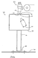
- FIG. 2 shows a TPC calibration system 30 capable of enabling determination of a TPC for a laser cutting tool 23.
- the calibration system 30 has an aperture assembly 40 and a light sensing device such as a digital camera 60. It is preferred that the calibration system 30 has a housing 32 for enclosing the digital camera 60, where the housing 32 has an opening 34.
- the housing 32 is preferably mounted on a stand 36 and baseplate 38 for attachment of the calibration system 30 to a floor surface 39.
- the aperture assembly 40 has an aperture (to be discussed below) for allowing light from the tool 23 to pass from a first side 42 of the aperture assembly 40 to a second side 44 of the aperture assembly 40.
- the digital camera 60 captures an image of the second side 44, and generates a signal corresponding to passage of the light to the second side 44. It is important to note that while the digital camera 60 provides the preferred functionality for this purpose, any type of light sensing device may be used without parting from the spirit and scope of the invention.
- a first layer 41 contains an aperture 43.
- a second layer 45 is disposed between the first layer 41 and the beam cutting tool 23 (FIG.2).
- the second layer 45 is preferably a thin layer of semi-transparent material used to capture an image of the laser beam. It is important to note that the second layer 45 allows enough intensity through to the second side 44 so that the digital camera 60 can detect the beam.
- a protective layer of film 46 is disposed between the second layer 45 and the tool such that the film 46 provides protection to the second layer 45.
- the first layer 41 is preferably made of sheet metal and is bolted to the housing 32 with a connection mechanism 33.
- FIG. 4 demonstrates the capture of images from the second side 44 of the aperture assembly 40 by the digital camera 60. It can be seen that since the digital camera 60 is pointed toward the aperture 43 in the first layer 41, an intensity image can be detected. Every time the laser beam 22 passes the aperture 43, an image appears on the backside of the second layer 45. This image is detected by the digital camera 60 by virtue of the increase in light intensity caused by the laser light. When the light intensity reaches a predetermined trigger level 61 or matches certain criteria, an output signal is generated by the camera 60 to notify the robot controller that the beam 22 has reached the aperture 43. As will be discussed below, this output signal can either be an initialization signal associated with the preferred set-up procedure, or a centerpoint signal associated with the actual calibration procedure.
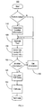
- FIG. 5 the preferred method for determining a TCP for a laser cutting tool is shown at 100. It can be seen that location information regarding the aperture assembly is automatically determined at step 110. This involves both locating a plane containing the aperture assembly, and determining an orientation of the aperture contained within the aperture assembly.
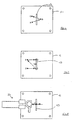
- FIG. 6 demonstrates the preferred approach to locating the plane containing the aperture assembly 40 (FIG. 3).
- first layer 41 of the aperture assembly 40 is shown for ease of discussion.
- locating the plane containing the aperture assembly 40 also provides information regarding the orientation of the housing 32 (FIG. 3) in the robot's base coordinate system. Specifically, this is done by locating three points (A, B, C) in the plane containing the aperture assembly.
- the robot controller is able to know when the nozzle of the tool is the predetermined distance d from the aperture assembly 40. Calculating the plane based on points A, B and C allows the laser cutting tool to be positioned perpendicularly to the plane.
- the orientation of the aperture is determined as shown in FIG. 7. This is done by moving the laser beam from point D across the aperture assembly until the digital camera detects the laser beam and generates an initialization signal for point E, which corresponds to passage of the light through the aperture 43. This allows location of one of the edges of the aperture 43.
- initialization coordinate information is stored.
- the laser cutting tool is then moved to point F, where the searching procedure is repeated a second time to find a second point G along the same edge of the aperture 43.
- the two points E and G and the plane in space allow calculation of point H at the center of the edge of the aperture 43.
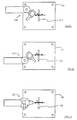
- the tool is oscillated across the aperture assembly such that light from the tool periodically passes through the aperture assembly. This is preferably done four to eight times so that center point coordinate information can be determined at step 130 with a large enough sampling. It is also important to note that this is done for a given tool orientation. For example, the orientation shown in FIG. 8 is zero degrees with respect to perpendicularity of the tool 23.
- the TCP is calculated for the current tool orientation based on the center point coordinate information. This is preferably done by simply averaging the center point coordinate information. The result is point I representing the first estimate for the TCP.
- the present invention provides for repeating the oscillating, determining, and calculating steps 120, 130, 140 for a plurality of tool orientations at steps 150 and 152.
- the beam tool can be turned to a +45° angle (around the center axis of the beam) from the original orientation.
- the result is point J.
- the laser cutting tool is turned to a -45° angle (around the center axis of the laser beam) from the original orientation. This orientation results in point K.
- FIG. 11 shows the determination of point L by tilting the beam tool 30° around the Y-axis and executing the above steps.
- step 140 provides a TCP offset for calibration of the tool by effectively calculating the difference between the actual TCPs and the correct one.
- Step 160 can be performed using any number of functions and techniques known in the art, because the input used is identical to that of conventional approaches.
- the present invention provides a unique method and system for determining TCPs.
Landscapes
- Engineering & Computer Science (AREA)
- Human Computer Interaction (AREA)
- Manufacturing & Machinery (AREA)
- Physics & Mathematics (AREA)
- General Physics & Mathematics (AREA)
- Automation & Control Theory (AREA)
- Robotics (AREA)
- Mechanical Engineering (AREA)
- Laser Beam Processing (AREA)
- Machine Tool Sensing Apparatuses (AREA)
- Length Measuring Devices By Optical Means (AREA)
- Mounting And Adjusting Of Optical Elements (AREA)
Applications Claiming Priority (2)
| Application Number | Priority Date | Filing Date | Title |
|---|---|---|---|
| US09/658,726 US6467178B1 (en) | 2000-09-11 | 2000-09-11 | Method and apparatus for beam tool center point calibration |
| US658726 | 2000-09-11 |
Publications (2)
| Publication Number | Publication Date |
|---|---|
| EP1186385A2 true EP1186385A2 (de) | 2002-03-13 |
| EP1186385A3 EP1186385A3 (de) | 2003-11-19 |
Family
ID=24642421
Family Applications (1)
| Application Number | Title | Priority Date | Filing Date |
|---|---|---|---|
| EP01121818A Withdrawn EP1186385A3 (de) | 2000-09-11 | 2001-09-11 | Verfahren und Vorrichtung zur Kalibrierung des Mittelpunkts eines Laserwerkzeuges |
Country Status (3)
| Country | Link |
|---|---|
| US (1) | US6467178B1 (de) |
| EP (1) | EP1186385A3 (de) |
| NO (1) | NO20014398L (de) |
Families Citing this family (7)
| Publication number | Priority date | Publication date | Assignee | Title |
|---|---|---|---|---|
| EP1503175A1 (de) * | 2003-07-28 | 2005-02-02 | Leica Geosystems AG | Vorrichtung und Verfahren zum Kalibrieren der Ausrichtung eines Prüflings |
| US7581331B2 (en) * | 2008-01-22 | 2009-09-01 | United Microelectronics Corp. | Calibration device for nozzle and calibration method for nozzle |
| WO2010110872A1 (en) * | 2009-03-24 | 2010-09-30 | Perkinelmer Health Sciences, Inc. | System and auto-alignment method for determining position using a discrete contact probe |
| US8406922B2 (en) * | 2009-07-31 | 2013-03-26 | Fanuc Robotics America, Inc. | System and method for setting the tool center point of a robotic tool |
| FR2962568B1 (fr) * | 2010-07-09 | 2012-08-17 | Renault Sa | Procede de controle de la qualite d'une soudure |
| EP2745985A1 (de) * | 2012-12-21 | 2014-06-25 | Maquinaria Geka S.A. | Laserpositionierer für Stanzmaschinen |
| CN115597508B (zh) * | 2021-07-07 | 2025-07-29 | 东莞市宇瞳光学科技股份有限公司 | 一种光圈的孔径检测装置及孔径检测方法 |
Family Cites Families (13)
| Publication number | Priority date | Publication date | Assignee | Title |
|---|---|---|---|---|
| GB1312663A (en) * | 1970-05-28 | 1973-04-04 | Ti Group Services Ltd | Optical control means |
| DE2509586C3 (de) * | 1975-03-05 | 1980-03-27 | Gebrueder Boehringer Gmbh, 7320 Goeppingen | Einrichtung zum Einstellen einer Werkzeugschneide an einer spanabhebenden Werkzeugmaschine |
| AU552364B2 (en) * | 1980-09-02 | 1986-05-29 | Amada Company Limited | Laser cutting |
| JPH08384B2 (ja) * | 1987-09-16 | 1996-01-10 | ファナック株式会社 | ツール先端点の自動設定方式 |
| US5251156A (en) * | 1990-08-25 | 1993-10-05 | Carl-Zeiss-Stiftung, Heidenheim/Brenz | Method and apparatus for non-contact measurement of object surfaces |
| EP0648358A4 (de) * | 1992-05-18 | 1995-12-13 | Sensor Adaptive Mach | Verfahren und gerät zur steuerung von stangen und anderen werkzeugmaschinen. |
| US5457367A (en) | 1993-08-06 | 1995-10-10 | Cycle Time Corporation | Tool center point calibration apparatus and method |
| US5675229A (en) | 1994-09-21 | 1997-10-07 | Abb Robotics Inc. | Apparatus and method for adjusting robot positioning |
| GB9601679D0 (en) * | 1996-01-27 | 1996-03-27 | Renishaw Plc | Ball bar apparatus for calibrating a machine |
| US5718054A (en) * | 1996-05-15 | 1998-02-17 | Kitajima; Tomoyuki | Device for displaying a center point of a laser beam in a vertical-degree measuring system |
| US5910719A (en) | 1996-09-17 | 1999-06-08 | Cycle Time Corporation | Tool center point calibration for spot welding guns |
| SE508228C2 (sv) * | 1997-05-07 | 1998-09-14 | Inst Verkstadstek Forsk Ivf | Anordning för detektering och beräkning av en laserstråles fokusläge, form och effektfördelning |
| WO1999010136A1 (en) * | 1997-08-28 | 1999-03-04 | Proteus Corporation | Laser calibration of robotics systems |
-
2000
- 2000-09-11 US US09/658,726 patent/US6467178B1/en not_active Expired - Fee Related
-
2001
- 2001-09-11 EP EP01121818A patent/EP1186385A3/de not_active Withdrawn
- 2001-09-11 NO NO20014398A patent/NO20014398L/no not_active Application Discontinuation
Also Published As
| Publication number | Publication date |
|---|---|
| EP1186385A3 (de) | 2003-11-19 |
| NO20014398D0 (no) | 2001-09-11 |
| US6467178B1 (en) | 2002-10-22 |
| NO20014398L (no) | 2002-03-12 |
Similar Documents
| Publication | Publication Date | Title |
|---|---|---|
| KR102227194B1 (ko) | 터치 프로브에 대하여 시각 시스템을 켈리브레이팅하기 위한 시스템 및 방법 | |
| US5396331A (en) | Method for executing three-dimensional measurement utilizing correctively computing the absolute positions of CCD cameras when image data vary | |
| EP0866308B1 (de) | Optischer Profilsensor | |
| JP5679560B2 (ja) | 寸法測定装置、寸法測定方法及び寸法測定装置用のプログラム | |
| JP3027609B2 (ja) | 幾何学的配列の測定方法及び装置 | |
| US7005606B2 (en) | Laser machine tool with image sensor for registration of workhead guidance system | |
| US7400414B2 (en) | Hand-size structured-light three-dimensional metrology imaging system and method | |
| EP1411322B1 (de) | Optischer Sensor zur Messung der Position und Lage eines Objekts in drei Dimensionen | |
| EP2193332B1 (de) | Optischer triangulationssensor | |
| CA2541635A1 (en) | Hybrid sensing apparatus for adaptive robotic processes | |
| EP1447644A1 (de) | Messung von räumlichen Koordinaten | |
| KR940007899B1 (ko) | 공작물의 3차원위치계측방법과 공작물의 포착방법 | |
| EP3711908B1 (de) | Kalibrierungsvorrichtung für roboterarm | |
| US6467178B1 (en) | Method and apparatus for beam tool center point calibration | |
| JP5467962B2 (ja) | 測定設定データ作成装置、測定設定データ作成方法、測定設定データ作成装置用のプログラム及び寸法測定装置 | |
| JP6767843B2 (ja) | 画像測定装置 | |
| US7405388B2 (en) | Video centerscope for machine alignment | |
| JP2009509778A (ja) | 生産機械におけるカメラの校正方法及びシステム | |
| US5831735A (en) | Non-contact optical measurement probe | |
| JP2005093710A (ja) | 切削装置におけるチャックテーブルの回転軸と顕微鏡の中心との位置合わせ方法 | |
| US5351316A (en) | Image processing apparatus | |
| US20050235506A1 (en) | Method for profilometer position registration | |
| JPH08122021A (ja) | 寸法測定器 | |
| KR101657546B1 (ko) | 로봇과 변위센서 간 캘리브레이션 장치 및 이를 이용한 캘리브레이션 방법 | |
| KR20150137034A (ko) | 레이저와 레이저 광센서를 이용하여 폐 궤적 곡선을 결정하는 방법 및 폐 궤적 곡선을 결정하는 장치 |
Legal Events
| Date | Code | Title | Description |
|---|---|---|---|
| PUAI | Public reference made under article 153(3) epc to a published international application that has entered the european phase |
Free format text: ORIGINAL CODE: 0009012 |
|
| AK | Designated contracting states |
Kind code of ref document: A2 Designated state(s): AT BE CH CY DE DK ES FI FR GB GR IE IT LI LU MC NL PT SE TR |
|
| AX | Request for extension of the european patent |
Free format text: AL;LT;LV;MK;RO;SI |
|
| RAP1 | Party data changed (applicant data changed or rights of an application transferred) |
Owner name: ABB AUTOMATION, INC. |
|
| PUAL | Search report despatched |
Free format text: ORIGINAL CODE: 0009013 |
|
| AK | Designated contracting states |
Kind code of ref document: A3 Designated state(s): AT BE CH CY DE DK ES FI FR GB GR IE IT LI LU MC NL PT SE TR |
|
| AX | Request for extension of the european patent |
Extension state: AL LT LV MK RO SI |
|
| RIC1 | Information provided on ipc code assigned before grant |
Ipc: 7B 23K 26/00 B Ipc: 7G 05B 19/401 B Ipc: 7B 25J 9/16 A |
|
| RAP1 | Party data changed (applicant data changed or rights of an application transferred) |
Owner name: ABB INC. |
|
| AKX | Designation fees paid | ||
| REG | Reference to a national code |
Ref country code: DE Ref legal event code: 8566 |
|
| STAA | Information on the status of an ep patent application or granted ep patent |
Free format text: STATUS: THE APPLICATION IS DEEMED TO BE WITHDRAWN |
|
| 18D | Application deemed to be withdrawn |
Effective date: 20040520 |