EP1186085B1 - Elektromotorischer antrieb - Google Patents
Elektromotorischer antrieb Download PDFInfo
- Publication number
- EP1186085B1 EP1186085B1 EP01921338A EP01921338A EP1186085B1 EP 1186085 B1 EP1186085 B1 EP 1186085B1 EP 01921338 A EP01921338 A EP 01921338A EP 01921338 A EP01921338 A EP 01921338A EP 1186085 B1 EP1186085 B1 EP 1186085B1
- Authority
- EP
- European Patent Office
- Prior art keywords
- safety
- control unit
- electromotive drive
- motor
- time
- Prior art date
- Legal status (The legal status is an assumption and is not a legal conclusion. Google has not performed a legal analysis and makes no representation as to the accuracy of the status listed.)
- Expired - Lifetime
Links
- 230000003111 delayed effect Effects 0.000 claims abstract 2
- 230000003287 optical effect Effects 0.000 claims description 6
- 238000012545 processing Methods 0.000 claims description 4
- 230000004913 activation Effects 0.000 claims 3
- 230000009849 deactivation Effects 0.000 claims 2
- 230000011664 signaling Effects 0.000 claims 1
- 230000006870 function Effects 0.000 description 4
- 230000001960 triggered effect Effects 0.000 description 3
- 230000000007 visual effect Effects 0.000 description 3
- 230000007547 defect Effects 0.000 description 2
- 238000013461 design Methods 0.000 description 2
- 238000000034 method Methods 0.000 description 2
- 230000005540 biological transmission Effects 0.000 description 1
- 238000010586 diagram Methods 0.000 description 1
- 230000008034 disappearance Effects 0.000 description 1
- 238000012544 monitoring process Methods 0.000 description 1
- 230000008447 perception Effects 0.000 description 1
- 238000004171 remote diagnosis Methods 0.000 description 1
- 238000012795 verification Methods 0.000 description 1
Images
Classifications
-
- H—ELECTRICITY
- H02—GENERATION; CONVERSION OR DISTRIBUTION OF ELECTRIC POWER
- H02H—EMERGENCY PROTECTIVE CIRCUIT ARRANGEMENTS
- H02H3/00—Emergency protective circuit arrangements for automatic disconnection directly responsive to an undesired change from normal electric working condition with or without subsequent reconnection ; integrated protection
- H02H3/02—Details
- H02H3/05—Details with means for increasing reliability, e.g. redundancy arrangements
-
- H—ELECTRICITY
- H02—GENERATION; CONVERSION OR DISTRIBUTION OF ELECTRIC POWER
- H02H—EMERGENCY PROTECTIVE CIRCUIT ARRANGEMENTS
- H02H7/00—Emergency protective circuit arrangements specially adapted for specific types of electric machines or apparatus or for sectionalised protection of cable or line systems, and effecting automatic switching in the event of an undesired change from normal working conditions
- H02H7/08—Emergency protective circuit arrangements specially adapted for specific types of electric machines or apparatus or for sectionalised protection of cable or line systems, and effecting automatic switching in the event of an undesired change from normal working conditions for dynamo-electric motors
- H02H7/0833—Emergency protective circuit arrangements specially adapted for specific types of electric machines or apparatus or for sectionalised protection of cable or line systems, and effecting automatic switching in the event of an undesired change from normal working conditions for dynamo-electric motors for electric motors with control arrangements
- H02H7/0844—Fail safe control, e.g. by comparing control signal and controlled current, isolating motor on commutation error
Definitions
- the invention relates to an electric motor drive, in particular a furniture drive with an operable by a manual switch, a control board containing control unit and with a safety unit or with a safety circuit.
- the candidate electromotive drive is known in many designs. The particular design depends on the intended use. Are known drives with a drive motor and an output member and so-called double drives with two drive motors and two output members. For use in the furniture sector, the eligible drives are linear drives.
- the motor drives via a reduction gear to a spindle on which a spindle nut is rotatably mounted, which carries a lifting tube or a similar component, which can be connected to a component to be adjusted.
- the citation US-A-5771511 shows an electromotive furniture drive, with an operable by a hand switch, a control board containing control unit and with a safety unit or a safety circuit, the control unit is equipped with at least one safety module and / or a safety circuit for self-monitoring and remote diagnosis of the control unit.
- a so-called first fault safety is required, ie, if, for example, a shutdown function is not triggered, it must nevertheless be ensured that the shutdown process is carried out or, for example, that the drive can not be switched on if fault or Damage to electrical or electronic components.
- the invention has for its object to make an electric motor drive of the type described in more detail so that the required by the electrical appliance standard first error safety is met, so that there is no danger to an operator or a user if by failure or defect of an electrical or electronic component, a necessary switching operation can not be triggered, or that the failure of an electrical or electronic component of the electric motor drive can not be put into operation.
- the control unit is equipped with at least one safety module and / or a safety circuit for controlling the control unit such that between the actuation of an actuating element of the manual switch and the start of the engine or the motors, a functional control of the control unit.
- the control unit controls itself, so that the failure or defect of electrical or electronic components is detected immediately. For example, the function can be switched off if the contacts of a relay no longer come loose.
- a release to all engines if the conditions for the startup are given.
- a release switching element preferably a transistor of the switching logic. If the function is ensured, this can be done, for example, by lighting up an optical display element, preferably a light-emitting diode in the manual switch or at a clearly visible location. This optical display element should then preferably glow as long as the actuator is pressed.
- control unit is equipped with a plurality of safety modules or multiple safety circuits, in which the error signals can be fed.
- the safety modules or the safety circuits can be designed so that each safety module or each safety circuit is designed for very specific error signals. So that the user is immediately informed of an error message, it is provided that an optical and / or acoustic signal is then generated.
- the bridging time is relatively short, so that the error message (acoustically and / or optically) is short-term.
- the disappearance is a sign that the verification process has been completed.
- the short-term error message arises because after actuation of an actuating element and before tightening the associated relay and the motor then starting and after releasing the actuator and before the fall of the associated relay and the motor then stopped a certain time interval passes, in which an error condition is met, which is however no longer fulfilled after this time interval in the normal case.
- the resulting short-term and again disappearing error message can be regarded as a kind of functional check.
- this time interval may happen in certain cases that this time interval be so short that the audible and visual annunciators are too slow, due to their own signal processing runtimes, to indicate a detectable signal.
- an appropriate extension of the pick-up time and the fall time of the motor relay is simulated by appropriate means such that the annunciator outputs the signal described above for control during a period of time sufficient for human perception.
- a delay element preferably, the operating time of the relay associated with each motor can be extended.
- the operating time and the fall time of the relay associated with each motor is extended.
- This delay element is preferably arranged in the controller, the error signal processing or in the reporting device. However, it can also be arranged elsewhere.
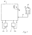
- the control board 10 containing a control board is equipped in the illustrated embodiment with two security devices 11, 12, which could also be circuits that are provided in the control board of the control unit 10.
- the control unit 10 is connected via a control cable 13 with a manual switch 14.
- the transmission of the triggered by the manual switch 14 signals can also be done wirelessly.
- the safety components are first activated, preferably in the delay time of the relays assigned to the motors, in order to check the functional safety. In the event of an error or multiple errors signals are fed into the EingCode 11a and 12a of the safety modules 11, 12, so that, for example, a start of the motors is prevented.
- the manual switch 14 may be equipped with a visual display in the form of a light-emitting diode 15, which illuminates when an error as long as the corresponding actuator of the manual switch 14 is pressed.
- a visual display in the form of a light-emitting diode 15, which illuminates when an error as long as the corresponding actuator of the manual switch 14 is pressed.
- an optical or acoustic display element 16 may also be installed in the control unit 10. According to the FIG. 1 An optical and acoustic display element can be used. However, it is also possible that only one of the two display elements is used.
- a delay element to extend, for example, the operating time and the fall time of each motor associated relay, so during this time the function control can be carried out.
- Essential is the meaningful self-control of the control unit so that theressford is guaranteed.
Landscapes
- Control Of Electric Motors In General (AREA)
- Valve Device For Special Equipments (AREA)
- Lubrication Of Internal Combustion Engines (AREA)
- Motor And Converter Starters (AREA)
- Manipulator (AREA)
- Primary Cells (AREA)
- Secondary Cells (AREA)
Description
- Die Erfindung betrifft einen elektromotorischen Antrieb, insbesondere einen Möbelantrieb mit einer von einem Handschalter betätigbaren, eine Steuerplatine enthaltenden Steuereinheit sowie mit einer Sicherheitseinheit oder mit einem Sicherheitsschaltkreis.
- Der in Frage kommende elektromotorische Antrieb ist in vielen Ausführungen bekannt. Die jeweilige Ausführung richtet sich nach dem Verwendungszweck. Bekannt sind Antriebe mit einem Antriebsmotor und einem Abtriebsglied sowie sogenannten Doppelantrieben mit zwei Antriebsmotoren und zwei Abtriebsgliedern. Für den Einsatz im Möbelbereich sind die in Frage kommenden Antriebe Linearantriebe. Der Motor treibt über ein Untersetzungsgetriebe eine Spindel an, auf die eine Spindelmutter drehfest aufgesetzt ist, die ein Hubrohr oder ein ähnliches Bauteil trägt, welches an ein zu verstellendes Bauteil angeschlossen werden kann.
- Die Entgegenhaltung
US-A-5771511 zeigt einen elektromotorischen Möbelantrieb, mit einer von einem Handschalter betätigbaren, eine Steuerplatine enthaltende Steuereinheit sowie mit einer Sicherheitseinheit oder einem Sicherheitsschaltkreis, wobei die Steuereinheit mit wenigstens einem Sicherheitsbaustein und/oder einem Sicherheitsschaltkreis zur Selbstüberwachung und Ferndiagnose der Steuereinheit ausgestattet ist. - Da die Antriebe im häuslichen und medizinischen Bereich sowie im Pflegebereich eingesetzt werden, werden entsprechend einer Norm hohe Sicherheitsanforderungen gestellt.
- Gemäß der erwähnten Norm für elektrische Geräte wird eine sog. Erstfehlersicherheit gefordert, d.h., wenn beispielsweise eine Funktion zum Abschalten nicht ausgelöst wird, muß trotzdem sichergestellt sein, daß der Abschaltvorgang durchgeführt wird, oder daß beispielsweise der Antrieb nicht eingeschaltet werden kann, wenn Fehler oder Schäden an elektrischen oder elektronischen Bauteilen vorliegen.
- Der Erfindung liegt die Aufgabe zugrunde, einen elektromotorischen Antrieb der eingangs näher beschriebenen Art so zu gestalten, daß die durch die Elektrogerätenorm geforderte Erstfehlersicherheit erfüllt wird, so daß für einen Bediener oder für einen Benutzer keine Gefahr besteht, wenn durch Ausfall oder Defekt einer elektrischen oder elektronischen Komponente ein notwendiger Schaltvorgang nicht mehr ausgelöst werden kann, oder daß beim Ausfall eines elektrischen oder elektronischen Bauteils der elektromotorische Antrieb nicht in Betrieb gesetzt werden kann.
- Die gestellte Aufgabe wird gemäß einem ersten Lösungsvorschlag gelöst, indem eine Funktionskontrolle der Sicherheitseinheit oder des Sicherheitsschaltkreises in der durch die Anzugs- oder Abfallverzögerung bedingten Zeit des jedem Motor zugeordneten Relais erfolgt. Gemäß einem zweiten Lösungsvorschlag ist vorgesehen, daß die Steuereinheit mit wenigstens einem Sicherheitsbaustein und/oder einem Sicherheitsschaltkreis zur Kontrolle der Steuereinheit derart ausgestattet ist, daß zwischen dem Betätigen eines Betätigungselementes des Handschalters und dem Anlauf des Motors oder der Motore eine Funktionskontrolle der Steuereinheit erfolgt. Durch die erfindungsgemäßen Gestaltungen kontrolliert sich die Steuereinheit selbst, so daß der Ausfall oder der Defekt von elektrischen oder elektronischen Bauteilen sofort erkannt wird. So kann beispielsweise die Funktion abgeschaltet werden, wenn sich die Kontakte eines Relais nicht mehr lösen. So kann beispielsweise durch einen vergleich eine Freigabe an alle Motoren erfolgen, wenn die Voraussetzungen für den Anlauf gegeben sind. Bei einer Fehlermeldung kann erreicht werden, daß alle Motoren abgeschaltet werden, wenn das Fehlersignal ein Freigabeschaltelement, vorzugsweise einen Transistor der Schaltlogik sperrt. Ist die Funktion sichergestellt, kann dies beispielsweise durch Aufleuchten eines optischen Anzeigeelementes, vorzugsweise einer Leuchtdiode im Handschalter oder an einer gut sichtbaren Stelle erfolgen. Dieses optische Anzeigeelement sollte dann vorzugsweise solange leuchten, wie das Betätigungselement gedrückt wird.
- In weiterer Ausgestaltung ist noch vorgesehen, daß die Steuereinheit mit mehreren Sicherheitsbausteinen oder mehreren Sicherheitsschaltkreisen ausgestattet ist, in die die Fehlersignale einspeisbar sind. Dabei können die Sicherheitsbausteine bzw. die Sicherheitsschaltkreise so ausgelegt sein, daß jeder Sicherheitsbaustein bzw. jeder Sicherheitsschaltkreis für ganz bestimmte Fehlersignale ausgelegt ist. Damit der Benutzer sofort auf eine Fehlermeldung hingewiesen wird, ist vorgesehen, daß dann ein optisches und/oder ein akustisches Signal erzeugt wird.
- Die Überbrückungszeit ist relativ kurz, so daß auch die Fehlermeldung (akustisch und/oder optisch) kurzzeitig ist. Das Verschwinden ist ein Zeichen dafür, daß der Überprüfungsvorgang abgeschlossen ist. Die kurzzeitige Fehlermeldung entsteht deswegen, weil nach Betätigung eines Betätigungselementes und vor dem Anziehen des zugeordneten Relais und dem danach anlaufenden Motor sowie nach dem Loslassen des Betätigungselementes und vor dem Abfallen des zugeordneten Relais und dem danach stillstehenden Motor ein bestimmtes Zeitintervall vergeht, in dem eine Fehlerbedingung erfüllt ist, die jedoch nach Ablauf dieses Zeitintervalls im Normalfall nicht mehr erfüllt ist. Die daraus resultierende kurzzeitig auftretende und wieder verschwindende Fehlermeldung kann als eine Art Funktionskontrolle angesehen werden.
- Es kann in bestimmten Fällen passieren, daß dieses Zeitintervall so kurz ist, daß die akustischen und optischen Meldeeinrichtungen aufgrund ihrer eigenen Signalverarbeitungslaufzeiten zu langsam sind, um ein erkennbares Signal anzuzeigen. Zum Erhalt eines wahrnehmbaren akustischen und/oder optischen Signals wird mit geeigneten Mitteln eine Verlängerung der Anzugszeit und der Abfallzeit des Motorrelais so simuliert, daß die Meldeeinrichtung das oben beschriebene Signal zur Kontrolle während eines Zeitraumes ausgibt, der für die menschliche Wahrnehmung ausreichend ist. Es ist deshalb vorgesehen, daß mittels eines Verzögerungselementes vorzugsweise die Anzugszeit des jedem Motor zugeordneten Relais verlängerbar ist. In weiterer Ausgestaltung ist jedoch vorgesehen, daß die Anzugszeit und die Abfallzeit des jedem Motor zugeordneten Relais verlängert wird. Dieses Verzögerungselement ist vorzugsweise in der Steuerung, der Fehlersignalverarbeitung oder in der Meldeeinrichtung angeordnet. Es kann jedoch auch an anderer Stelle angeordnet werden.
-
- Figur 1
- die Steuereinheit eines erfindungsgemäßen elektromotorischen Antriebes als Blockschaltbild.
- Die eine Steuerplatine enthaltende Steuereinheit 10 ist im dargestellten Ausführungsbeispiel mit zwei Sicherheitsbausteinen 11, 12 ausgestattet, die auch Schaltkreise sein könnten, die in der Steuerplatine der Steuereinheit 10 vorgesehen sind. Die Steuereinheit 10 ist über ein Steuerkabel 13 mit einem Handschalter 14 verbunden. Die Übertragung der vom Handschalter 14 ausgelösten Signale kann auch drahtlos erfolgen. Bei Betätigung eines der Betätigungselemente des Handschalters 14 werden zunächst vorzugsweise in der Verzögerungszeit der den Motoren zugeordneten Relais die Sicherheitsbausteine aktiviert, um die Funktionssicherheit zu prüfen. Im Falle eines Fehlers oder mehrerer Fehler werden Signale in die Eingängc 11a bzw. 12a der Sicherheitsbausteine 11, 12 eingespeist, so daß beispielsweise ein Anlaufen der Motore verhindert wird.
- Wie die
Figur 1 zeigt, kann der Handschalter 14 mit einer optischen Anzeige in Form einer Leuchtdiode 15 ausgestattet sein, die bei einem Fehler solange leuchtet, wie das entsprechende Betätigungselement des Handschalters 14 gedrückt ist. Ferner kann ein optisches oder akustisches Anzeigeelement 16 auch in der Steuereinheit 10 installiert sein. Entsprechend derFigur 1 kann ein optisches und akustisches Anzeigeelement verwendet werden. Es ist jedoch auch möglich, daß nur eines der beiden Anzeigeelemente zum Einsatz kommt. - In nicht näher dargestellter Weise kann an einer geeigneten Stelle, zweckmäßigerweise jedoch in der Steuerung oder der Fehlersignalverarbeitung oder in der Meldecinrichtung ein Verzögerugselement eingesetzt werden, um beispielsweise die Anzugszeit und die Abfallzeit des jeden Motor zugeordneten Relais zu verlängern, damit während dieser Zeit die Funktionskontrolle auch durchgeführt werden kann.
- Die Erfindung ist nicht auf das darstellte Ausführungsbeispiel beschränkt. Wesentlich ist die sinngemäße Selbstkontrolle der Steuereinheit, damit die Erstfehlersicherheit gewährleistet ist.
Claims (8)
- Elektromotorischer Antrieb, insbesondere Möbelantrieb, mit einer von einem Handschalter (14) betätigbaren, eine Steuerplatine enthaltende Steuereinheit (10) sowie mit einer Sicherheitseinheit oder einem Sicherheitsschaltkreis, dadurch gekennzeichnet, daß eine Funktionskontrolle der Sicherheitseinheit oder des Sicherheitsschaltkreises in der durch die Anzugs- oder Abfallverzögerung bedingten Zeit des jedem Motor zugeordneten Relais erfolgt.
- Elektromotorischer Antrieb, insbesondere Möbelantrieb, mit einer von einem Handschalter (14) betätigbaren, eine Steuerplatine enthaltende Steuereinheit (10), sowie mit einer Sicherheitseinheit oder einem Sicherheitsschaltkreis, wobei die Steuereinheit (10) mit wenigstens einem Sicherheitsbaustein (11, 12) und/oder einem Sicherheitsschaltkreis zur Kontrolle der Steuereinheit (10) ausgestattet ist, dadurch gekennzeichnet, daß zwischen dem Betätigen eines Betätigungselementes des Handschalters (14) und dem Anlauf des Motors oder der Motore eine Funktionskontrolle der Steuereinheit (10) erfolgt.
- Elektromotorischer Antrieb nach Anspruch 1 oder 2, dadurch gekennzeichnet, daß die Steuereinheit (10) mit mehreren Sicherheitsbausteinen (11,12) oder mehreren Sicherheitsschaltkreisen ausgestattet ist, in die Fehlersignale einspeisbar sind.
- Elektromotorischer Antrieb nach Anspruch 3, dadurch gekennzeichnet, daß jeder Sicherheitsbaustein für vorbestimmte, unterschiedliche Fehlersignale ausgerüstet ist.
- Elektromotorischer Antrieb nach einem oder mehreren der vorhergehenden Ansprüche 1 bis 4, dadurch gekennzeichnet, daß bei einer Fehlermeldung ein optisches und/oder akustisches Signal (15,16) erzeugbar ist.
- Elektromotorischer Antrieb nach einem oder mehreren der vorhergehenden Ansprüche 1 bis 5, dadurch gekennzeichnet, daß mittels eines Verzögerungselementes vorzugsweise die Anzugszeit des jeden Motor zugeordneten Relais verlängerbar ist.
- Elektromotorischer Antrieb nach Anspruch 6, dadurch gekennzeichnet, daß die Anzugszeit und die Abfallzeit des jeden Motor zugeordneten Relais verlängerbar ist.
- Elektromotorischer Antrieb nach einem oder mehreren der vorhergehenden Ansprüche 1 bis 7, dadurch gekennzeichnet, daß das Verzögerungselement vorzugsweise in der Steuerung oder in der Fehlersignalverarbeitung oder in der Meldeeinrichtung angeordnet ist.
Applications Claiming Priority (3)
| Application Number | Priority Date | Filing Date | Title |
|---|---|---|---|
| DE20005054U | 2000-03-20 | ||
| DE20005054U DE20005054U1 (de) | 2000-03-20 | 2000-03-20 | Elektromotorischer Antrieb |
| PCT/EP2001/002885 WO2001071875A1 (de) | 2000-03-20 | 2001-03-15 | Elektromotorischer antrieb |
Publications (2)
| Publication Number | Publication Date |
|---|---|
| EP1186085A1 EP1186085A1 (de) | 2002-03-13 |
| EP1186085B1 true EP1186085B1 (de) | 2009-04-22 |
Family
ID=7938989
Family Applications (1)
| Application Number | Title | Priority Date | Filing Date |
|---|---|---|---|
| EP01921338A Expired - Lifetime EP1186085B1 (de) | 2000-03-20 | 2001-03-15 | Elektromotorischer antrieb |
Country Status (7)
| Country | Link |
|---|---|
| US (1) | US6876166B2 (de) |
| EP (1) | EP1186085B1 (de) |
| AT (1) | ATE429725T1 (de) |
| DE (2) | DE20005054U1 (de) |
| DK (1) | DK1186085T3 (de) |
| ES (1) | ES2325979T3 (de) |
| WO (1) | WO2001071875A1 (de) |
Families Citing this family (1)
| Publication number | Priority date | Publication date | Assignee | Title |
|---|---|---|---|---|
| DE102008009664A1 (de) * | 2008-02-18 | 2009-08-20 | Paul Hettich Gmbh & Co. Kg | Akustische Signalerzeugung in Möbeln mit elektromechanischer Antriebseinrichtung |
Family Cites Families (43)
| Publication number | Priority date | Publication date | Assignee | Title |
|---|---|---|---|---|
| DE2516951C3 (de) * | 1975-04-17 | 1981-09-03 | Robert Bosch Gmbh, 7000 Stuttgart | Steuereinrichtung zum Abschalten des Antriebsmotors eines elektrisch betriebenen Schraubers |
| US4114077A (en) * | 1977-04-01 | 1978-09-12 | Westinghouse Electric Corp. | Rotor overtemperature protection for electric motors |
| US4115859A (en) * | 1977-06-30 | 1978-09-19 | Dynamics Research Corporation | Back gauge controller |
| FR2430633A1 (fr) * | 1978-07-07 | 1980-02-01 | Sfena | Systeme de commande auto-surveille, d'un processus |
| US4319298A (en) * | 1979-08-28 | 1982-03-09 | General Electric Company | Motor protection device |
| US4484127A (en) * | 1982-05-28 | 1984-11-20 | Otis Elevator Company | Inverter power transistor protection |
| DE3401761C2 (de) * | 1984-01-19 | 1987-04-16 | Fresenius AG, 6380 Bad Homburg | Regeleinrichtung |
| DE3447090A1 (de) * | 1984-12-22 | 1986-06-26 | Heidelberger Druckmaschinen Ag, 6900 Heidelberg | Verfahren und einrichtung zur bremsenkontrolle eines bewegungsueberwachten und -gesteuerten antriebsmotors in einer druckmaschine |
| JPH0640756B2 (ja) * | 1984-12-26 | 1994-05-25 | 光洋精工株式会社 | ステツピングモ−タの異常検知装置 |
| DE3768893D1 (de) | 1986-09-26 | 1991-05-02 | Siemens Ag | Schalteinrichtung fuer die stromzufuhr an ein elektrisches geraet. |
| EP0468361B1 (de) * | 1990-07-26 | 1995-07-05 | DORMA GmbH + Co. KG | Begrenzung der Schliesskraft an der Schliesskante eines beweglichen Elementes |
| DE9011262U1 (de) * | 1990-07-31 | 1990-10-04 | Siemens AG, 8000 München | Einklemmschutz-Steueranordnung für die elektronische Überwachung eines Schließvorganges |
| DE4132208C1 (de) | 1991-09-27 | 1993-02-04 | Fraunhofer-Gesellschaft Zur Foerderung Der Angewandten Forschung Ev, 8000 Muenchen, De | |
| US5511183A (en) * | 1992-05-12 | 1996-04-23 | Fujitsu Limited | Non-volatile memory controlling apparatus and applications of the same to electronic computer peripheral equipments |
| JPH06133578A (ja) * | 1992-10-15 | 1994-05-13 | Konica Corp | 負荷通電回路の異常検出回路 |
| US5467002A (en) * | 1993-11-05 | 1995-11-14 | Reliance Medical Products, Inc. | Adjustable chair having programmable control switches |
| US5534782A (en) * | 1993-11-17 | 1996-07-09 | Controlled Power Limited Partnership | Automatic reclosing circuit breaker using controllable feeder transducer |
| DE4343191C2 (de) * | 1993-12-17 | 1996-04-25 | Dorma Gmbh & Co Kg | Automatische Tür |
| DE19504032C2 (de) * | 1994-05-02 | 1996-11-14 | Dorma Gmbh & Co Kg | Verfahren zur Regelung einer durch einen Antriebsmotor angetriebenen automatischen Tür |
| US5416399A (en) * | 1994-05-13 | 1995-05-16 | Brunson; Walter S. | On-site electric motor start-up diagnostic tool |
| DE4424020A1 (de) * | 1994-07-08 | 1996-01-11 | Telefunken Microelectron | Prüfverfahren für eine passive Sicherheitseinrichtung in Kraftfahrzeugen |
| US5587640A (en) * | 1994-09-28 | 1996-12-24 | Tetra Laval Holdings & Finance S.A. | Delayed safety braking apparatus for a servomotor control system |
| US5601178A (en) * | 1995-03-16 | 1997-02-11 | Zaharia; Vlad | Detection of escalator safety circuit component operability |
| US5771511A (en) * | 1995-08-04 | 1998-06-30 | Hill-Rom, Inc. | Communication network for a hospital bed |
| US5677608A (en) * | 1995-11-16 | 1997-10-14 | Westinghouse Air Brake Company | Embedded duplex local control panel |
| DE19612596A1 (de) * | 1996-03-29 | 1997-10-02 | Fahrzeugklimaregelung Gmbh | Anschlags- und Blockiererkennung bei einem Elektromotor |
| DE19717743A1 (de) | 1997-04-26 | 1998-10-29 | Aquatec Peter Schmidt Gmbh | Vorrichtung zum Absenken bzw. Anheben von Kranken und Behinderten in eine bzw. aus einer Badewanne |
| US5818195A (en) * | 1997-06-05 | 1998-10-06 | Mcg, Inc. | Dual state controller for brushless electric motors |
| JPH1113635A (ja) * | 1997-06-30 | 1999-01-19 | Matsushita Electric Ind Co Ltd | 圧縮機駆動装置 |
| US5925998A (en) * | 1997-07-21 | 1999-07-20 | Olson; Eric O. | Energy saving motor control device |
| US5923145A (en) * | 1997-08-15 | 1999-07-13 | S-B Power Tool Company | Controller for variable speed motor |
| US6456195B1 (en) * | 1997-09-03 | 2002-09-24 | Dennis L. Berndt | Vehicle lighting control system |
| US6225768B1 (en) * | 1998-08-12 | 2001-05-01 | The Cookson Company | Automatic door safety system with multiple safety modes |
| FR2782855B1 (fr) * | 1998-08-25 | 2000-11-17 | Jouan | Dispositif de controle de la vitesse de rotation d'un moteur electrique et appareil de centrifugation equipe d'un tel dispositif |
| FR2783371B1 (fr) * | 1998-09-16 | 2000-12-01 | Valeo Equip Electr Moteur | Dispositif pour la commande de l'alimentation d'un moteur electrique de demarreur de vehicule et demarreur comportant un tel dispositif |
| US6184795B1 (en) * | 1998-10-02 | 2001-02-06 | Siemens Energy & Automation, Inc. | Motor controller having dead ended winding detection capability on a single phase line |
| US6392318B1 (en) * | 1998-10-28 | 2002-05-21 | Eigenpoint Company | Programmable emergency-stop circuit |
| US6218951B1 (en) * | 1999-01-29 | 2001-04-17 | Western Technology | Safety circuit |
| US6121746A (en) * | 1999-06-10 | 2000-09-19 | General Electric Company | Speed reduction switch |
| DE50014492D1 (de) * | 1999-12-06 | 2007-08-30 | Siemens Ag | Verfahren und Schaltungsanordnung zum Einschalten einer Leistungsendstufe |
| DE10012050B4 (de) * | 2000-03-14 | 2004-02-26 | OKIN Gesellschaft für Antriebstechnik mbH & Co. KG | Anordnung zum Verstellen von beweglichen Möbelteilen |
| US6882155B2 (en) * | 2001-04-19 | 2005-04-19 | Vince J Lazzaro | Remotely actuated, circuit testing emergency stop apparatus and method |
| US6683432B2 (en) * | 2001-09-12 | 2004-01-27 | Eigenpoint Company | Safety circuit with automatic recovery |
-
2000
- 2000-03-20 DE DE20005054U patent/DE20005054U1/de not_active Expired - Lifetime
-
2001
- 2001-03-15 DE DE50114849T patent/DE50114849D1/de not_active Expired - Lifetime
- 2001-03-15 ES ES01921338T patent/ES2325979T3/es not_active Expired - Lifetime
- 2001-03-15 US US09/979,015 patent/US6876166B2/en not_active Expired - Fee Related
- 2001-03-15 WO PCT/EP2001/002885 patent/WO2001071875A1/de not_active Ceased
- 2001-03-15 EP EP01921338A patent/EP1186085B1/de not_active Expired - Lifetime
- 2001-03-15 AT AT01921338T patent/ATE429725T1/de not_active IP Right Cessation
- 2001-03-15 DK DK01921338T patent/DK1186085T3/da active
Also Published As
| Publication number | Publication date |
|---|---|
| ES2325979T3 (es) | 2009-09-28 |
| US6876166B2 (en) | 2005-04-05 |
| ATE429725T1 (de) | 2009-05-15 |
| DE50114849D1 (de) | 2009-06-04 |
| WO2001071875A1 (de) | 2001-09-27 |
| DE20005054U1 (de) | 2000-05-18 |
| US20020158594A1 (en) | 2002-10-31 |
| DK1186085T3 (da) | 2009-08-24 |
| EP1186085A1 (de) | 2002-03-13 |
Similar Documents
| Publication | Publication Date | Title |
|---|---|---|
| EP1277011B2 (de) | Modulares sicherheitsschaltgeräte-system | |
| DE102010025675B3 (de) | Sicherheitsschaltungsanordnung zum fehlersicheren Ein- und Ausschalten einer gefährlichen Anlage | |
| EP1738382A1 (de) | Sicherheitsschalteinrichtung für eine sicherheitsschaltung | |
| WO2003085313A2 (de) | Vorrichtung zum fehlersicheren abschalten eines elektrischen verbrauchers, insbesondere in industriellen produktionsanlagen | |
| WO2006099925A1 (de) | Sicherheitsschaltvorrichtung zum sicheren abschalten eines elektrischen verbrauchers | |
| EP3192091A1 (de) | Überwachter adaptierbarer notausschalter | |
| EP1869687B1 (de) | Sicherheitsschaltvorrichtung zum sicheren abschalten eines elektrischen verbrauchers | |
| DE3341472A1 (de) | Schaltanordnung mit einem mikrorechner | |
| EP1629513B1 (de) | Ansteuervorrichtung für sicherheitskritische komponenten und entsprechendes verfahren | |
| EP1364459B1 (de) | Sicherheitsschaltvorrichtung | |
| EP1667302B1 (de) | Verfahren und Vorrichtung zur Erfassung eines fehlerhaften Stromes oder einer fehlerhaften Spannung und Abschaltung der Versorgungsspannung | |
| DE102006027135B3 (de) | Verfahren zum Betrieb einer Vorrichtung, insbesondere eines Sicherheitsschalters, und die Vorrichtung | |
| EP1847891A1 (de) | Sichere Parametrierung einer Sicherheitsschaltungsvorrichtung | |
| EP1186085A1 (de) | Elektromotorischer antrieb | |
| EP3414637B1 (de) | Sicherheitsschaltvorrichtung | |
| EP1493063B1 (de) | Elektromotorische antriebsanordnung mit erstfehlersicherheitssystem | |
| DE102006030911B3 (de) | Schaltungsanordnung für eigenüberwachte Relaisfunktionseinheit | |
| DE202011050467U1 (de) | Möbelstück mit einem Betätigungssystem zur Verstellung wenigstens eines beweglichen Elements | |
| EP0863360B1 (de) | Ansteuerungssystem für elektromechanische Lineareinheiten zur Fehlersicherung | |
| EP1351107A1 (de) | Sicherheitssystem für einen elektrischen Antrieb | |
| EP1341201A2 (de) | Elektromotorische Verstellanordnung | |
| DE544970C (de) | Elektrische Signalanlage zur Anzeige einer AEnderung in dem Betriebszustande mehrerer Anlageteile mit einem akustischen Signalapparat und einzelnen, jeder Stoerungsstelle zugeordneten, von Hand abstellbaren und nach Beseitigung der Stoerung wieder in die Ausgangsstellung zurueckgehenden Signalrelais | |
| DE102006061476B3 (de) | Elektrische Steuerung | |
| DE102010011938A1 (de) | Steuerungssystem für elektromotorisch betätigbare Verstelleinrichtungen sowie Verfahren zum Erzeugen von fehlersicheren Steuersignalen für elektromotorisch betätigbare Verstelleinrichtungen | |
| DE2002353B2 (de) | Einrichtung zum erkennen und unterscheiden von fehlersignalen |
Legal Events
| Date | Code | Title | Description |
|---|---|---|---|
| PUAI | Public reference made under article 153(3) epc to a published international application that has entered the european phase |
Free format text: ORIGINAL CODE: 0009012 |
|
| 17P | Request for examination filed |
Effective date: 20010829 |
|
| AK | Designated contracting states |
Kind code of ref document: A1 Designated state(s): AT BE CH CY DE DK ES FI FR GB GR IE IT LI LU MC NL PT SE TR |
|
| GRAP | Despatch of communication of intention to grant a patent |
Free format text: ORIGINAL CODE: EPIDOSNIGR1 |
|
| GRAS | Grant fee paid |
Free format text: ORIGINAL CODE: EPIDOSNIGR3 |
|
| GRAA | (expected) grant |
Free format text: ORIGINAL CODE: 0009210 |
|
| RAP1 | Party data changed (applicant data changed or rights of an application transferred) |
Owner name: DEWERT ANTRIEBS- UND SYSTEMTECHNIK GMBH |
|
| AK | Designated contracting states |
Kind code of ref document: B1 Designated state(s): AT BE CH CY DE DK ES FI FR GB GR IE IT LI LU MC NL PT SE TR |
|
| REG | Reference to a national code |
Ref country code: GB Ref legal event code: FG4D Free format text: NOT ENGLISH |
|
| REG | Reference to a national code |
Ref country code: CH Ref legal event code: EP |
|
| REG | Reference to a national code |
Ref country code: IE Ref legal event code: FG4D |
|
| REF | Corresponds to: |
Ref document number: 50114849 Country of ref document: DE Date of ref document: 20090604 Kind code of ref document: P |
|
| REG | Reference to a national code |
Ref country code: DK Ref legal event code: T3 |
|
| REG | Reference to a national code |
Ref country code: ES Ref legal event code: FG2A Ref document number: 2325979 Country of ref document: ES Kind code of ref document: T3 |
|
| PG25 | Lapsed in a contracting state [announced via postgrant information from national office to epo] |
Ref country code: PT Free format text: LAPSE BECAUSE OF FAILURE TO SUBMIT A TRANSLATION OF THE DESCRIPTION OR TO PAY THE FEE WITHIN THE PRESCRIBED TIME-LIMIT Effective date: 20090822 Ref country code: FI Free format text: LAPSE BECAUSE OF FAILURE TO SUBMIT A TRANSLATION OF THE DESCRIPTION OR TO PAY THE FEE WITHIN THE PRESCRIBED TIME-LIMIT Effective date: 20090422 |
|
| PG25 | Lapsed in a contracting state [announced via postgrant information from national office to epo] |
Ref country code: SE Free format text: LAPSE BECAUSE OF FAILURE TO SUBMIT A TRANSLATION OF THE DESCRIPTION OR TO PAY THE FEE WITHIN THE PRESCRIBED TIME-LIMIT Effective date: 20090722 |
|
| REG | Reference to a national code |
Ref country code: IE Ref legal event code: FD4D |
|
| PG25 | Lapsed in a contracting state [announced via postgrant information from national office to epo] |
Ref country code: IE Free format text: LAPSE BECAUSE OF FAILURE TO SUBMIT A TRANSLATION OF THE DESCRIPTION OR TO PAY THE FEE WITHIN THE PRESCRIBED TIME-LIMIT Effective date: 20090422 |
|
| PLBE | No opposition filed within time limit |
Free format text: ORIGINAL CODE: 0009261 |
|
| STAA | Information on the status of an ep patent application or granted ep patent |
Free format text: STATUS: NO OPPOSITION FILED WITHIN TIME LIMIT |
|
| 26N | No opposition filed |
Effective date: 20100125 |
|
| BERE | Be: lapsed |
Owner name: DEWERT ANTRIEBS- UND SYSTEMTECHNIK G.M.B.H. Effective date: 20100331 |
|
| REG | Reference to a national code |
Ref country code: NL Ref legal event code: V1 Effective date: 20101001 |
|
| PG25 | Lapsed in a contracting state [announced via postgrant information from national office to epo] |
Ref country code: MC Free format text: LAPSE BECAUSE OF NON-PAYMENT OF DUE FEES Effective date: 20100331 Ref country code: GR Free format text: LAPSE BECAUSE OF FAILURE TO SUBMIT A TRANSLATION OF THE DESCRIPTION OR TO PAY THE FEE WITHIN THE PRESCRIBED TIME-LIMIT Effective date: 20090723 |
|
| REG | Reference to a national code |
Ref country code: CH Ref legal event code: PL |
|
| PG25 | Lapsed in a contracting state [announced via postgrant information from national office to epo] |
Ref country code: NL Free format text: LAPSE BECAUSE OF NON-PAYMENT OF DUE FEES Effective date: 20101001 |
|
| PG25 | Lapsed in a contracting state [announced via postgrant information from national office to epo] |
Ref country code: CH Free format text: LAPSE BECAUSE OF NON-PAYMENT OF DUE FEES Effective date: 20100331 Ref country code: BE Free format text: LAPSE BECAUSE OF NON-PAYMENT OF DUE FEES Effective date: 20100331 Ref country code: LI Free format text: LAPSE BECAUSE OF NON-PAYMENT OF DUE FEES Effective date: 20100331 |
|
| PG25 | Lapsed in a contracting state [announced via postgrant information from national office to epo] |
Ref country code: IT Free format text: LAPSE BECAUSE OF FAILURE TO SUBMIT A TRANSLATION OF THE DESCRIPTION OR TO PAY THE FEE WITHIN THE PRESCRIBED TIME-LIMIT Effective date: 20090422 |
|
| PG25 | Lapsed in a contracting state [announced via postgrant information from national office to epo] |
Ref country code: AT Free format text: LAPSE BECAUSE OF NON-PAYMENT OF DUE FEES Effective date: 20100315 |
|
| PG25 | Lapsed in a contracting state [announced via postgrant information from national office to epo] |
Ref country code: CY Free format text: LAPSE BECAUSE OF FAILURE TO SUBMIT A TRANSLATION OF THE DESCRIPTION OR TO PAY THE FEE WITHIN THE PRESCRIBED TIME-LIMIT Effective date: 20090422 |
|
| PG25 | Lapsed in a contracting state [announced via postgrant information from national office to epo] |
Ref country code: LU Free format text: LAPSE BECAUSE OF NON-PAYMENT OF DUE FEES Effective date: 20100315 |
|
| PG25 | Lapsed in a contracting state [announced via postgrant information from national office to epo] |
Ref country code: TR Free format text: LAPSE BECAUSE OF FAILURE TO SUBMIT A TRANSLATION OF THE DESCRIPTION OR TO PAY THE FEE WITHIN THE PRESCRIBED TIME-LIMIT Effective date: 20090422 |
|
| REG | Reference to a national code |
Ref country code: DE Ref legal event code: R082 Ref document number: 50114849 Country of ref document: DE Representative=s name: LOESENBECK UND KOLLEGEN, DE |
|
| REG | Reference to a national code |
Ref country code: DE Ref legal event code: R082 Ref document number: 50114849 Country of ref document: DE Representative=s name: LOESENBECK UND KOLLEGEN, DE Effective date: 20130729 Ref country code: DE Ref legal event code: R081 Ref document number: 50114849 Country of ref document: DE Owner name: DEWERTOKIN GMBH, DE Free format text: FORMER OWNER: DEWERT ANTRIEBS- UND SYSTEMTECHNIK GMBH, 32278 KIRCHLENGERN, DE Effective date: 20130729 |
|
| REG | Reference to a national code |
Ref country code: GB Ref legal event code: 732E Free format text: REGISTERED BETWEEN 20140306 AND 20140312 |
|
| REG | Reference to a national code |
Ref country code: FR Ref legal event code: CD Owner name: DEWERTOKIN GMBH, DE Effective date: 20140314 |
|
| REG | Reference to a national code |
Ref country code: ES Ref legal event code: PC2A Owner name: DEWERTOKIN GMBH Effective date: 20140711 |
|
| REG | Reference to a national code |
Ref country code: FR Ref legal event code: PLFP Year of fee payment: 16 |
|
| REG | Reference to a national code |
Ref country code: FR Ref legal event code: PLFP Year of fee payment: 17 |
|
| PGFP | Annual fee paid to national office [announced via postgrant information from national office to epo] |
Ref country code: FR Payment date: 20170323 Year of fee payment: 17 |
|
| PGFP | Annual fee paid to national office [announced via postgrant information from national office to epo] |
Ref country code: GB Payment date: 20170327 Year of fee payment: 17 Ref country code: DK Payment date: 20170327 Year of fee payment: 17 |
|
| PGFP | Annual fee paid to national office [announced via postgrant information from national office to epo] |
Ref country code: DE Payment date: 20170407 Year of fee payment: 17 |
|
| PGFP | Annual fee paid to national office [announced via postgrant information from national office to epo] |
Ref country code: ES Payment date: 20170323 Year of fee payment: 17 |
|
| REG | Reference to a national code |
Ref country code: DE Ref legal event code: R119 Ref document number: 50114849 Country of ref document: DE |
|
| REG | Reference to a national code |
Ref country code: DK Ref legal event code: EBP Effective date: 20180331 |
|
| GBPC | Gb: european patent ceased through non-payment of renewal fee |
Effective date: 20180315 |
|
| PG25 | Lapsed in a contracting state [announced via postgrant information from national office to epo] |
Ref country code: DE Free format text: LAPSE BECAUSE OF NON-PAYMENT OF DUE FEES Effective date: 20181002 |
|
| PG25 | Lapsed in a contracting state [announced via postgrant information from national office to epo] |
Ref country code: GB Free format text: LAPSE BECAUSE OF NON-PAYMENT OF DUE FEES Effective date: 20180315 |
|
| PG25 | Lapsed in a contracting state [announced via postgrant information from national office to epo] |
Ref country code: FR Free format text: LAPSE BECAUSE OF NON-PAYMENT OF DUE FEES Effective date: 20180331 |
|
| PG25 | Lapsed in a contracting state [announced via postgrant information from national office to epo] |
Ref country code: DK Free format text: LAPSE BECAUSE OF NON-PAYMENT OF DUE FEES Effective date: 20180331 |
|
| REG | Reference to a national code |
Ref country code: ES Ref legal event code: FD2A Effective date: 20190911 |
|
| PG25 | Lapsed in a contracting state [announced via postgrant information from national office to epo] |
Ref country code: ES Free format text: LAPSE BECAUSE OF NON-PAYMENT OF DUE FEES Effective date: 20180316 |