EP1184996B1 - Ein nichtkoheräntes DP-MOK Empfangsverfahren mit Mehrwegkombination und Empfänger dafür - Google Patents
Ein nichtkoheräntes DP-MOK Empfangsverfahren mit Mehrwegkombination und Empfänger dafür Download PDFInfo
- Publication number
- EP1184996B1 EP1184996B1 EP01402223A EP01402223A EP1184996B1 EP 1184996 B1 EP1184996 B1 EP 1184996B1 EP 01402223 A EP01402223 A EP 01402223A EP 01402223 A EP01402223 A EP 01402223A EP 1184996 B1 EP1184996 B1 EP 1184996B1
- Authority
- EP
- European Patent Office
- Prior art keywords
- energy
- signal
- channel
- mok
- weighting
- Prior art date
- Legal status (The legal status is an assumption and is not a legal conclusion. Google has not performed a legal analysis and makes no representation as to the accuracy of the status listed.)
- Expired - Lifetime
Links
Images


Classifications
-
- H—ELECTRICITY
- H04—ELECTRIC COMMUNICATION TECHNIQUE
- H04B—TRANSMISSION
- H04B1/00—Details of transmission systems, not covered by a single one of groups H04B3/00 - H04B13/00; Details of transmission systems not characterised by the medium used for transmission
- H04B1/69—Spread spectrum techniques
- H04B1/707—Spread spectrum techniques using direct sequence modulation
- H04B1/7097—Interference-related aspects
- H04B1/711—Interference-related aspects the interference being multi-path interference
- H04B1/7113—Determination of path profile
-
- H—ELECTRICITY
- H04—ELECTRIC COMMUNICATION TECHNIQUE
- H04L—TRANSMISSION OF DIGITAL INFORMATION, e.g. TELEGRAPHIC COMMUNICATION
- H04L23/00—Apparatus or local circuits for systems other than those covered by groups H04L15/00 - H04L21/00
- H04L23/02—Apparatus or local circuits for systems other than those covered by groups H04L15/00 - H04L21/00 adapted for orthogonal signalling
-
- H—ELECTRICITY
- H04—ELECTRIC COMMUNICATION TECHNIQUE
- H04B—TRANSMISSION
- H04B1/00—Details of transmission systems, not covered by a single one of groups H04B3/00 - H04B13/00; Details of transmission systems not characterised by the medium used for transmission
- H04B1/69—Spread spectrum techniques
- H04B1/707—Spread spectrum techniques using direct sequence modulation
- H04B1/7097—Interference-related aspects
- H04B1/711—Interference-related aspects the interference being multi-path interference
- H04B1/7115—Constructive combining of multi-path signals, i.e. RAKE receivers
- H04B1/7117—Selection, re-selection, allocation or re-allocation of paths to fingers, e.g. timing offset control of allocated fingers
-
- H—ELECTRICITY
- H04—ELECTRIC COMMUNICATION TECHNIQUE
- H04B—TRANSMISSION
- H04B1/00—Details of transmission systems, not covered by a single one of groups H04B3/00 - H04B13/00; Details of transmission systems not characterised by the medium used for transmission
- H04B1/69—Spread spectrum techniques
- H04B1/707—Spread spectrum techniques using direct sequence modulation
- H04B1/7097—Interference-related aspects
- H04B1/711—Interference-related aspects the interference being multi-path interference
- H04B1/7115—Constructive combining of multi-path signals, i.e. RAKE receivers
- H04B1/712—Weighting of fingers for combining, e.g. amplitude control or phase rotation using an inner loop
-
- H—ELECTRICITY
- H04—ELECTRIC COMMUNICATION TECHNIQUE
- H04B—TRANSMISSION
- H04B1/00—Details of transmission systems, not covered by a single one of groups H04B3/00 - H04B13/00; Details of transmission systems not characterised by the medium used for transmission
- H04B1/69—Spread spectrum techniques
- H04B1/707—Spread spectrum techniques using direct sequence modulation
- H04B1/709—Correlator structure
- H04B1/7093—Matched filter type
- H04B2001/70935—Matched filter type using a bank of matched fileters, e.g. Fast Hadamard Transform
Definitions
- the present invention relates to a non-coherent DP-MOK reception method with multipath combination and a corresponding receiver.
- the invention has a general application in digital communications and more particularly in wireless local area networks (WLAN), in local wireless subscriber loops (WLL), in mobile telephony, in home automation and telecollect, in communication in the transport, etc ...
- WLAN wireless local area networks
- WLL local wireless subscriber loops
- mobile telephony in home automation and telecollect, in communication in the transport, etc ...
- the invention relates to the spread spectrum technique. It is known that this technique consists in the modulation of a digital symbol to be transmitted by a pseudo-random sequence known to the user. Each sequence is composed of N elements called “chips", whose duration is the Nth of the duration of a symbol. This results in a signal whose spectrum is spread over a range N times wider than that of the original signal.
- the demodulation consists in correlating the received signal with the sequence used on transmission in order to find the starting symbol.
- this technique has a drawback which is its low spectral efficiency.
- the ratio of the bit rate to the occupied bandwidth If each data symbol contains m bits, the bit rate is m times the symbol rate, mDs. As at the occupied band, it is equal to twice the frequency in "chips", that is to say at 2N times the flow in symbols, ie 2NDs.
- a spectral efficiency equal to the ratio m D s two NOT D s , is m two NOT .
- CDMA code division multiple access
- MC-CDMA synchronous variant
- phase modulation it is most often a binary modulation, denoted BPSK, or quaternary, denoted QPSK.
- BPSK binary modulation
- QPSK quaternary
- a differential demodulator multiplies between the signal to be demodulated and its delayed version of a symbol period.
- two signal channels are used, one which processes the component of the signal in phase with a carrier and another which processes the component in quadrature with the carrier.
- each symbol is associated with transmitting a signal taken from a set of orthogonal signals.
- These signals may be spreading codes of the same family of orthogonal codes. In this case, the modulation also realizes spreading. But these signals may also not be perfectly orthogonal because the orthogonality constraint is less strong than it seems. But of course, in this case the performance is worse.
- a known MOK receiver is illustrated in the appended FIG. It shows a battery of suitable filters 10 1 , 10 2 , ..., 10 M , followed by as many samplers 12 1 , 12 2 , ..., 12 M , circuits 14 1 , 14 2 ,. .., 14 M determination of the module or the square of the sampled signal module, a circuit 16 for determining the signal that has the strongest module, in other words determining the number of the channel corresponding to the strongest signal, a circuit 18 which, from the number of this channel, restores the code and the symbol.
- the MOK technique knows a variant called MBOK ("M-ary Bi-Orthogonal Keying") of adding to the set of orthogonal signals used in a MOK modulation their opposites to constitute a set of 2M signals, which are obviously not all orthogonal between them.
- MBOK M-ary Bi-Orthogonal Keying
- the demodulation still uses M correlators, adapted to each of the M orthogonal codes, but also requires means for recovering the sign.
- MOK and MBOK modulations are used in some digital communications systems, in conjunction with a coherent reception structure, which requires knowledge of the phase of the carrier.
- the sending of a preamble, before the transmission of useful data is a conventional method for estimating this phase.
- the phase of the carrier undergoes variations that can be rapid and that the receiving system must detect and compensate. This is usually achieved by the periodic issue of preambles which then occupy the channel and cause a decrease in the useful data rate.
- the durations of the preamble and the payload packet must be less than the coherence time of the channel (time during which the channel is considered to be stationary).
- the complexity of the receiving structure is increased.
- non-coherent, or differentially coherent, demodulation schemes that do not require knowledge of the phase information.
- These techniques eliminate the use of long preambles, phase estimators and phase derators, at the cost of a slight loss of sensitivity.
- the non-coherent demodulation greatly simplifies the processing of the diversity of the propagation paths since each path has, among others, its own phase (and therefore would require its own phase estimator in a coherent diagram).
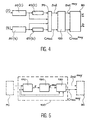
- FIG. 2 thus shows a receiver comprising an antenna 20, a local oscillator 22, a multiplier 24, an amplifier 26, a matched filter 28, a delay line 30, a multiplier 32, an integrator 34 and a decision circuit 36 .
- the matched filter 28 performs the correlation operation between the received signal and the spreading sequence that was used to transmit the data.
- the principle of the differential phase modulation chosen on transmission causes the information to be borne by the phase difference between the signals at the output of the matched filter 28 and the output of the delay line 30. This information is restored. by the multiplier 32.
- Each propagation path corresponds to a correlation peak at the output of the multiplier 32.
- the role of the integrator 34 consists in taking into account the information provided by each of the transmission paths. spread. Since the propagation paths are, in a multipath environment, statistically independent, a particular diversity-based processing is performed with this particular receiver technique, the order of which can be high when the impulse response is complex.
- the decision circuit 26 makes it possible to recover the transmitted data and, in addition, to regenerate the clock.
- the signals can be processed as illustrated in the appended FIG.
- the receiver shown comprises two analogous channels, one for processing the part I of the signal in phase with the carrier and the other for processing the part Q in quadrature with this same carrier.
- the channel I comprises first adapted filtering means 50 (I) capable of fulfilling a first filter function corresponding to the pseudo-random sequence used on transmission; these first means deliver samples I k .
- the channel I also comprises first delay means 60 (I) capable of filling a first delay function of a duration equal to the period Ts of the symbols and delivering samples I k-1 .
- the channel Q comprises second adapted filtering means 50 (Q), capable of filling a second filtering function, always corresponding to the pseudo-random sequence; these second means deliver samples Q k ; the channel Q further comprises second delay means 60 (Q) capable of performing a delay function of a duration Ts and delivering Q k-1 samples.
- the multiplier 70 delivers product combinations of these samples and in particular a signal denoted Dot (k) which is equal to I k I k-1 + Q k Q k-1 and a signal denoted Cross (k) equal to Q k I k-1 -I k Q k-1 .
- the circuit of FIG. 3 is completed by a circuit 90 processing the signals Dot (k) and Cross (k) and delivering a clock signal H and the data D.
- a programming means 72 controls the assembly.
- the simple integration processing carried out in a differential receiver of known type therefore corresponds to the sum not only of the energies conveyed by all the propagation paths but also signals which are not representative of propagation paths, which deteriorates the signal-to-signal ratio. noise. In other words, in this technique, the correlation peaks are not isolated.
- RAKE meaning "rake” in English. It consists of isolating a certain number of propagation paths and adding only the energies conveyed by these paths.
- a certain number of adapted filters make it possible to probe a channel and therefore to place the teeth of the "rake", other correlators to track the most energetic routes.
- a treatment then makes it possible to sum the squares of the amplitudes of the paths retained.
- a Dot signal in the case where there is only one propagation path between the transmitter and the receiver, consists of sometimes positive or negative peaks, depending on the value of the binary information transmitted.
- the interval between two consecutive peaks corresponds to the duration Ts of a symbol.
- the peaks are double, triple, quadruple, etc ... for each symbol, the number of peaks detected being equal to the number of paths taken by the radio wave between transmitter and receiver.
- a simple integrator like the integrator 24 of FIG. 1, integrated in the circuit 90 of FIG. 2, will integrate all the present signals, that is to say both the peaks (corresponding to a true information), and noise (not corresponding to any information).
- the noise signal is therefore weak.
- the averaging of the instantaneous output makes it possible to keep, on the Dot moy and Cross moy outputs, the peaks corresponding to propagation paths (taking into account the stationarity hypothesis of the channel on the few symbols used) and to decrease very significantly. the level of noise generated by the electromagnetic environment, a frequency shift or a phase rotation.
- FIG. 5 illustrates a receiver according to this document.
- This receiver comprises means already described in Figure 3 and which have the same reference numerals. It further comprises a circuit 100 arranged between the multiplier 70 and the circuit 90 for restoring the data and regenerating the clock.
- An example of this circuit 100 is illustrated in FIG. 5. It comprises a circuit 110 for calculating the energy E, a calculation circuit 120 of the mean E moy , and a signal weighting circuit 130 Dot and Cross (in the following, to simplify, the rank k will be omitted in the notations).
- the circuit 130 delivers the weighted averaged signals, namely Dot moy and Cross moy , weighted signals which are then applied to the circuit 90.
- a mixed demodulation is used in that it partially takes over the MOK modulation and partly the differential phase modulation DP.
- the latter being of the differential type, the demodulation is non-coherent.
- a part of the bits of each symbol is thus transmitted according to the MOK technique, and another part is transmitted according to the DP technique, with spread spectrum by the pseudo-random sequence selected in the MOK part.
- we first restore the pseudo-random sequence used to the emission by adapted parallel filtering, thus a part of the bits of the symbol, and we differentially demodulate the filtered signal suitable for finding the other part of the bits. This preserves the advantages specific to each modulation / demodulation while increasing the spectral efficiency.
- DP-MOK which accounts for the differential nature of the phase demodulation part, and its combination with the MOK technique.
- a combination of the paths by weighting of the peaks is carried out in the differential demodulation part and this weighting is used in the MOK part, before selection of the most energetic channel.
- the treatment of diversity is therefore also done in the MOK part by weighting the energies of each channel.
- the estimation of the transmission channel takes place in the DP part but is exploited both in the DP part and in the MOK part.
- US-A-5 692 007 already describes a combined differential phase (DP) and multiple orthogonal signal (MOK) combination modulator.
- DP differential phase
- MOK multiple orthogonal signal
- the receiver described is a simplified version of a coherent receiver, where the phase is estimated at each symbol using a table and where the differential demodulation is performed by subtracting the phase of two consecutive symbols. It is therefore not a non-coherent reception as in the present invention.
- this document does not take into account multiple propagation paths using a RAKE structure.
- the receiver shown in FIG. 6 comprises a general input E connected to a plurality of M channels in parallel, with filters 201, 202, 203,..., 20M adapted to the pseudo-random spreading sequences used on transmission. , circuits 211, 212, 213, ..., 21M for calculating the power of the filtered signals, a circuit 230 for determining the channel containing the strongest filtered signal, this circuit having two outputs 231, 232, the first output the number of the channel containing the filtered signal of higher energy, a decoder MOK 250 which, starting from this number, delivers the first mMOK data that correspond to that particular code.
- the receiver further comprises a circuit 240 of the demultiplexer type able to select the filtered signal having the highest energy, this demultiplexer being controlled by the signal delivered by a second output 232 of the circuit 230, a differential demodulator 260 comprising means already described in connection with FIG. 2 (20, 22, 24) or with FIG. 3 (60 (I), 60 (Q), 70), and a decoder 270 able to restore the mDP second data transmitted by this differential modulation.
- a circuit 240 of the demultiplexer type able to select the filtered signal having the highest energy, this demultiplexer being controlled by the signal delivered by a second output 232 of the circuit 230
- a differential demodulator 260 comprising means already described in connection with FIG. 2 (20, 22, 24) or with FIG. 3 (60 (I), 60 (Q), 70)
- a decoder 270 able to restore the mDP second data transmitted by this differential modulation.
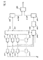
- the receiver shown in Figure 7 shows the means of the receiver of Figure 6, with the same reference numerals and shows the means for taking into account the diversity.
- These means comprise a set 265 for calculating the weighting coefficient, this set comprising, for example, a circuit 110 for calculating the energy E of the correlation peaks and a circuit 120 for calculating the average E moy of this energy as on FIG. 5.
- This average energy is used to weight, in a circuit 130, the signal delivered by the circuit 260 (for example the Dot and Cross signals) as in FIG. 4, and also to weight, in weighting circuits 221, 222, 223,..., 22M, the energies calculated by the preceding circuits 211, 212, 213,. 21M.
- This weighting is performed before the selection made by the circuit 230. In order for the switching to be successful, all the signals taken from the channels must be suitably delayed, which is represented by the delay line 235.
- Figure 8 (Plate 1/5) shows the variations of this BER rate as a function of the signal-to-noise ratio Eb / No abscissa and expressed in dB.
- Curve A corresponds to conventional DQPSK modulation with a bit rate of 1 Mbps
Landscapes
- Engineering & Computer Science (AREA)
- Computer Networks & Wireless Communication (AREA)
- Signal Processing (AREA)
- Digital Transmission Methods That Use Modulated Carrier Waves (AREA)
- Radio Transmission System (AREA)
Claims (2)
- Verfahren für den nicht-kohärenten Empfang eines Signals mit Spektrumspreizung und gemischter DP-MOK Modulation in Verbindung mit Mehrwegausbreitung, dadurch gekennzeichnet, dass es die folgenden Schritte umfasst:A) das Signal wird in einer Mehrzahl von M parallelen Kanälen verarbeitet; in jedem Kanal wird das Signal durch einen Filter gefiltert, der an eine dem Kanal eigene Pseudozufallssequenz angepasst ist; die Energie des gefilterten Signals wird gemessen; diese Energie wird mittels eines Gewichtungsfaktors gewichtet; der Kanal, der das als am stärksten gewichtete Signal enthält, wird bestimmt; die Nummer dieses Kanals wird decodiert, um erste Informationssymbole (mMOK) zu rekonstruieren;B) das gefilterte Signal mit der größten Energie wird ausgewählt; eine differentielle Phasendemodulation dieses Signals wird durchgeführt, was den Mehrwegen entsprechende Mehrfachkorrelationspeaks erzeugt; die Energie dieser Peaks wird berechnet; diese Energie wird durch den Gewichtungsfaktor gewichtet; diese gewichtete Energie wird decodiert, um zweite Informationssymbole (mDP) zu rekonstruieren;C) der Durchschnitt der Korrelationspeaks wird über eine bestimmte Zeit gebildet, die mehreren Informationssymbolen entspricht, wobei dieser Durchschnitt den Gewichtungsfaktor darstellt, der gleichzeitig auf die Energie des in jedem Kanal gefilterten Signals und auf die Energie der Korrelationspeaks einwirkt.
- Nicht-kohärenter Empfänger für ein Signal mit Spektrumspreizung und gemischter DP-MOK Modulation, um das Verfahren nach Anspruch 1 durchzuführen, dadurch gekennzeichnet, dass er aufweist:A) eine Vielzahl von M parallelen Kanälen, wobei jeder Kanal einen angepassten Filter (201, ..., 20M) mit einer dem Kanal eigenen Pseudozufallssequenz enthält; eine Schaltung zur Messung der Energie des gefilterten Signals (211, ..., 21M); eine Schaltung zur Gewichtung dieser Energie (221, ..., 22M) mittels eines Gewichtungsfaktors; Mittel (230), um den Kanal zu bestimmen, der das als mit der stärksten Energie gewichtete Signal enthält; einen MOK Decodierer(250), der die Nummer dieses Kanals empfängt und, als Antwort, erste Informationssymbole (mMOK) rekonstruiert;B) Mittel (240), um das gefilterte Signal mit der stärksten Energie auszuwählen; einen differentiellen Phasendemodulator (260), der Mehrfachkorrelationspeaks erzeugt, welche den Mehrfachwegen entsprechen; eine Schaltung (130) zur Gewichtung der Energie der Peaks mittels des Gewichtungsfaktors; einen PSK Decodierer (270), der zweite Informationssymbole (mDP) rekonstruiert;C) Mittel (265) zur Berechnung der durchschnittlichen Energie der Korrelationspeaks über eine bestimmte Dauer, mehreren Informationssymbolen entsprechend, wobei dieser Durchschnitt den Gewichtungsfaktor darstellt, wobei der Ausgang dieser Mittel (265) gleichzeitig mit den Gewichtungsschaltungen (221, ..., 22M) der verschiedenen Kanäle und mit der Schaltung (130) zur Gewichtung der Energie der Korrelationspeaks verbunden ist.
Applications Claiming Priority (2)
| Application Number | Priority Date | Filing Date | Title |
|---|---|---|---|
| FR0010981A FR2813474B1 (fr) | 2000-08-28 | 2000-08-28 | Procede de reception non coherente dp-mok avec combinaison de trajets multiples et recepteur correspondant |
| FR0010981 | 2000-08-28 |
Publications (2)
| Publication Number | Publication Date |
|---|---|
| EP1184996A1 EP1184996A1 (de) | 2002-03-06 |
| EP1184996B1 true EP1184996B1 (de) | 2006-11-08 |
Family
ID=8853759
Family Applications (1)
| Application Number | Title | Priority Date | Filing Date |
|---|---|---|---|
| EP01402223A Expired - Lifetime EP1184996B1 (de) | 2000-08-28 | 2001-08-24 | Ein nichtkoheräntes DP-MOK Empfangsverfahren mit Mehrwegkombination und Empfänger dafür |
Country Status (4)
| Country | Link |
|---|---|
| US (2) | US6956913B2 (de) |
| EP (1) | EP1184996B1 (de) |
| DE (1) | DE60124355T2 (de) |
| FR (1) | FR2813474B1 (de) |
Families Citing this family (6)
| Publication number | Priority date | Publication date | Assignee | Title |
|---|---|---|---|---|
| FR2795894B1 (fr) * | 1999-06-29 | 2001-10-05 | Commissariat Energie Atomique | Procede de transmission a modulation/demodulation multi-mak, emetteur et recepteur correspondants |
| US6754194B2 (en) * | 2002-03-18 | 2004-06-22 | Thomson Licensing S.A. | Method and apparatus for indicating the presence of a wireless local area network by detecting signature sequences |
| US7319658B2 (en) * | 2003-04-23 | 2008-01-15 | Northrop Grumman Corporation | Multirate, constant envelope, constant bandwidth, modulation, channelization, and detection system based on orthogonal bipolar spreading vectors including biorthogonal coding and including error-control |
| US20080079557A1 (en) * | 2006-09-29 | 2008-04-03 | Sensormatic Electronics Corporation | Radio frequency identification fast tag response method and system |
| US8699592B1 (en) | 2010-06-11 | 2014-04-15 | Marvell International Ltd. | Systems and methods for estimating decoder noise power in OFDM systems |
| DE102016119750B4 (de) * | 2015-10-26 | 2022-01-13 | Infineon Technologies Ag | Vorrichtungen und Verfahren zur Mehrkanalabtastung |
Family Cites Families (20)
| Publication number | Priority date | Publication date | Assignee | Title |
|---|---|---|---|---|
| US3819919A (en) * | 1972-12-08 | 1974-06-25 | Gunigle R Mc | Tracking system for time-displaced signals |
| US4222115A (en) * | 1978-03-13 | 1980-09-09 | Purdue Research Foundation | Spread spectrum apparatus for cellular mobile communication systems |
| FR2458179A1 (fr) * | 1979-05-31 | 1980-12-26 | Thomson Csf | Dispositif de decodage binaire et systemes de transmission comportant un tel dispositif |
| US4567588A (en) * | 1984-03-23 | 1986-01-28 | Sangamo Weston, Inc. | Synchronization system for use in direct sequence spread spectrum signal receiver |
| US5396516A (en) * | 1993-02-22 | 1995-03-07 | Qualcomm Incorporated | Method and system for the dynamic modification of control paremeters in a transmitter power control system |
| JPH06343085A (ja) * | 1993-04-07 | 1994-12-13 | Hitachi Ltd | 信号復調復号装置および信号復調復号方法 |
| FR2706709B1 (fr) * | 1993-06-16 | 1995-08-25 | Matra Communication | Procédé de synchronisation pour des communications radiotéléphoniques à accès multiple à répartition par codes. |
| US5361276A (en) * | 1993-09-13 | 1994-11-01 | At&T Bell Laboratories | All digital maximum likelihood based spread spectrum receiver |
| US5692007A (en) * | 1994-09-09 | 1997-11-25 | Omnipoint Corporation | Method and apparatus for differential phase encoding and decoding in spread-spectrum communication systems with continuous-phase modulation |
| FR2728415B1 (fr) * | 1994-12-19 | 1997-01-24 | Commissariat Energie Atomique | Procede de transmission a modulation et demodulation differentielle de phase a etalement de spectre utilisant des sequences pseudoaleatoires orthogonales |
| JPH09233138A (ja) * | 1996-02-22 | 1997-09-05 | Sony Corp | 情報伝送システムおよび情報受信装置、並びに情報伝送方法 |
| US6404732B1 (en) * | 1996-07-30 | 2002-06-11 | Agere Systems Guardian Corp. | Digital modulation system using modified orthogonal codes to reduce autocorrelation |
| US5790589A (en) * | 1996-08-14 | 1998-08-04 | Qualcomm Incorporated | System and method for rapidly reacquiring a pilot channel |
| US6289041B1 (en) * | 1997-02-11 | 2001-09-11 | Snaptrack, Inc. | Fast Acquisition, high sensitivity GPS receiver |
| JPH1168696A (ja) * | 1997-08-19 | 1999-03-09 | Sony Corp | 通信方法及び送信装置及び受信装置並びにセルラー無線通信システム |
| EP1021019A1 (de) * | 1999-01-15 | 2000-07-19 | Sony International (Europe) GmbH | Verfahren zur quasi-differentiellen Modulation und Demodulation von multi-amplituden Signalen und OFDM System |
| FR2791841B1 (fr) * | 1999-04-02 | 2001-05-11 | Commissariat Energie Atomique | Module recepteur et recepteur compose de plusieurs modules montes en cascade |
| FR2795894B1 (fr) * | 1999-06-29 | 2001-10-05 | Commissariat Energie Atomique | Procede de transmission a modulation/demodulation multi-mak, emetteur et recepteur correspondants |
| JP3796076B2 (ja) * | 1999-09-07 | 2006-07-12 | 松下電器産業株式会社 | Ofdm通信装置 |
| US6778514B1 (en) * | 2000-05-31 | 2004-08-17 | Cadence Design Systems, Inc. | Subspace combination of multisensor output signals |
-
2000
- 2000-08-28 FR FR0010981A patent/FR2813474B1/fr not_active Expired - Lifetime
-
2001
- 2001-08-24 DE DE60124355T patent/DE60124355T2/de not_active Expired - Lifetime
- 2001-08-24 US US09/935,548 patent/US6956913B2/en not_active Expired - Lifetime
- 2001-08-24 EP EP01402223A patent/EP1184996B1/de not_active Expired - Lifetime
-
2005
- 2005-10-17 US US11/253,192 patent/US7817709B2/en not_active Expired - Fee Related
Also Published As
| Publication number | Publication date |
|---|---|
| FR2813474B1 (fr) | 2002-12-13 |
| FR2813474A1 (fr) | 2002-03-01 |
| EP1184996A1 (de) | 2002-03-06 |
| DE60124355T2 (de) | 2007-08-30 |
| DE60124355D1 (de) | 2006-12-21 |
| US7817709B2 (en) | 2010-10-19 |
| US20020048332A1 (en) | 2002-04-25 |
| US6956913B2 (en) | 2005-10-18 |
| US20060109936A1 (en) | 2006-05-25 |
Similar Documents
| Publication | Publication Date | Title |
|---|---|---|
| EP0718983B1 (de) | Spreizspektrumdifferenzmodulation | |
| FR2601212A1 (fr) | Modem prevu pour l'utilisation dans des systemes de telecommunication comportant des chemins multiples | |
| EP1168739B1 (de) | Verfahren und Vorrichtung zur Schätzung der Impulsantwort eines Übertragungskanals, insbesondere für ein zellulares Mobiltelefon | |
| EP1260071B1 (de) | Verfahren und vorrichtung für kanalschäztung | |
| EP1041729B1 (de) | Verfahren zur Taktsynchronisierung eines digitalen Signals | |
| FR2942576A1 (fr) | Procede d'estimation d'un decalage de frequence porteuse dans un recepteur de signaux de telecommunication, notamment un dispositif mobile. | |
| US7817709B2 (en) | Non-coherent phase differential and multiple orthogonal signal reception | |
| EP1105975B1 (de) | Iterativer rake-empfänger und entsprechendes empfangsverfahren | |
| EP0917299A1 (de) | Digitale Direktsequenzspreizspektrumnachrichtenübertragung mit Störsignalgeneration | |
| EP0849889B1 (de) | Verfahren zum Mehrwegesignalempfang | |
| FR2751499A1 (fr) | Procede de demodulation differentielle numerique | |
| EP0917298B1 (de) | Differentieller Direktsequenzspreizspektrumempfänger mit gemischter Störsignalerzeugungsvorrichtung | |
| EP1041730B1 (de) | Empfangsmodul und Empfänger bestehend aus meheren kaskadierten Modulen | |
| EP1135855B1 (de) | Digitales filter mit paralleler architektur und spreizspektrumempfänger mit einem solchen filter | |
| FR2888076A1 (fr) | Procede de correction automatique de l'inversion spectrale dans un demodulateur et dispositif pour mettre en oeuvre le procede | |
| EP1065849B1 (de) | Übertragungsverfahren für multi-MOK Modulation/Demodulation | |
| FR2770058A1 (fr) | Procede de traitement d'un signal de transmission d'information par etalement de spectre et recepteur correspondant | |
| EP1400051A1 (de) | Übertragungsverfahren mit verringerter interferenz in ein sttd-schema | |
| EP1252722B1 (de) | Cdma-funkübertragungsverfahren mit zugriffskodes und empfänger dafür | |
| EP2146457A1 (de) | Zeitliches Synchronisierungsverfahren eines digitalen Signals, sowie entsprechende Vorrichtung und entsprechendes Computerprogrammprodukt. | |
| FR2776146A1 (fr) | Procede de demodulation de signaux representatifs de sequences emises dans un systeme de communications | |
| WO2001041382A1 (fr) | Dispositifs d'estimation de canal radio et de demodulation | |
| EP1693969B9 (de) | CDMA-Empfangsverfahren mit paralleler Interferenzunterdrückung, entsprechende Stufe und Empfänger |
Legal Events
| Date | Code | Title | Description |
|---|---|---|---|
| PUAI | Public reference made under article 153(3) epc to a published international application that has entered the european phase |
Free format text: ORIGINAL CODE: 0009012 |
|
| AK | Designated contracting states |
Kind code of ref document: A1 Designated state(s): AT BE CH CY DE DK ES FI FR GB GR IE IT LI LU MC NL PT SE TR Kind code of ref document: A1 Designated state(s): DE GB IT NL |
|
| AX | Request for extension of the european patent |
Free format text: AL;LT;LV;MK;RO;SI |
|
| 17P | Request for examination filed |
Effective date: 20020810 |
|
| AKX | Designation fees paid |
Free format text: DE GB IT NL |
|
| GRAP | Despatch of communication of intention to grant a patent |
Free format text: ORIGINAL CODE: EPIDOSNIGR1 |
|
| GRAC | Information related to communication of intention to grant a patent modified |
Free format text: ORIGINAL CODE: EPIDOSCIGR1 |
|
| GRAS | Grant fee paid |
Free format text: ORIGINAL CODE: EPIDOSNIGR3 |
|
| GRAA | (expected) grant |
Free format text: ORIGINAL CODE: 0009210 |
|
| AK | Designated contracting states |
Kind code of ref document: B1 Designated state(s): DE GB IT NL |
|
| PG25 | Lapsed in a contracting state [announced via postgrant information from national office to epo] |
Ref country code: IT Free format text: LAPSE BECAUSE OF FAILURE TO SUBMIT A TRANSLATION OF THE DESCRIPTION OR TO PAY THE FEE WITHIN THE PRESCRIBED TIME-LIMIT;WARNING: LAPSES OF ITALIAN PATENTS WITH EFFECTIVE DATE BEFORE 2007 MAY HAVE OCCURRED AT ANY TIME BEFORE 2007. THE CORRECT EFFECTIVE DATE MAY BE DIFFERENT FROM THE ONE RECORDED. Effective date: 20061108 Ref country code: NL Free format text: LAPSE BECAUSE OF FAILURE TO SUBMIT A TRANSLATION OF THE DESCRIPTION OR TO PAY THE FEE WITHIN THE PRESCRIBED TIME-LIMIT Effective date: 20061108 |
|
| REG | Reference to a national code |
Ref country code: GB Ref legal event code: FG4D Free format text: NOT ENGLISH |
|
| RAP2 | Party data changed (patent owner data changed or rights of a patent transferred) |
Owner name: COMMISSARIAT A L'ENERGIE ATOMIQUE |
|
| REF | Corresponds to: |
Ref document number: 60124355 Country of ref document: DE Date of ref document: 20061221 Kind code of ref document: P |
|
| NLT2 | Nl: modifications (of names), taken from the european patent patent bulletin |
Owner name: COMMISSARIAT A L'ENERGIE ATOMIQUE Effective date: 20061220 |
|
| GBT | Gb: translation of ep patent filed (gb section 77(6)(a)/1977) |
Effective date: 20070213 |
|
| NLV1 | Nl: lapsed or annulled due to failure to fulfill the requirements of art. 29p and 29m of the patents act | ||
| PLBE | No opposition filed within time limit |
Free format text: ORIGINAL CODE: 0009261 |
|
| STAA | Information on the status of an ep patent application or granted ep patent |
Free format text: STATUS: NO OPPOSITION FILED WITHIN TIME LIMIT |
|
| 26N | No opposition filed |
Effective date: 20070809 |
|
| PGFP | Annual fee paid to national office [announced via postgrant information from national office to epo] |
Ref country code: DE Payment date: 20180716 Year of fee payment: 18 |
|
| PGFP | Annual fee paid to national office [announced via postgrant information from national office to epo] |
Ref country code: GB Payment date: 20180726 Year of fee payment: 18 |
|
| REG | Reference to a national code |
Ref country code: DE Ref legal event code: R119 Ref document number: 60124355 Country of ref document: DE |
|
| GBPC | Gb: european patent ceased through non-payment of renewal fee |
Effective date: 20190824 |
|
| PG25 | Lapsed in a contracting state [announced via postgrant information from national office to epo] |
Ref country code: DE Free format text: LAPSE BECAUSE OF NON-PAYMENT OF DUE FEES Effective date: 20200303 |
|
| PG25 | Lapsed in a contracting state [announced via postgrant information from national office to epo] |
Ref country code: GB Free format text: LAPSE BECAUSE OF NON-PAYMENT OF DUE FEES Effective date: 20190824 |