EP1105975B1 - Iterativer rake-empfänger und entsprechendes empfangsverfahren - Google Patents
Iterativer rake-empfänger und entsprechendes empfangsverfahren Download PDFInfo
- Publication number
- EP1105975B1 EP1105975B1 EP99939481A EP99939481A EP1105975B1 EP 1105975 B1 EP1105975 B1 EP 1105975B1 EP 99939481 A EP99939481 A EP 99939481A EP 99939481 A EP99939481 A EP 99939481A EP 1105975 B1 EP1105975 B1 EP 1105975B1
- Authority
- EP
- European Patent Office
- Prior art keywords
- symbols
- block
- estimate
- receiver
- vector
- Prior art date
- Legal status (The legal status is an assumption and is not a legal conclusion. Google has not performed a legal analysis and makes no representation as to the accuracy of the status listed.)
- Expired - Lifetime
Links
- 238000000034 method Methods 0.000 title claims description 19
- 239000013598 vector Substances 0.000 claims description 41
- 230000008569 process Effects 0.000 claims description 13
- 238000001228 spectrum Methods 0.000 claims description 13
- 238000012804 iterative process Methods 0.000 claims description 9
- 239000011159 matrix material Substances 0.000 claims description 9
- 238000000354 decomposition reaction Methods 0.000 claims description 8
- 230000000644 propagated effect Effects 0.000 claims description 4
- 238000012545 processing Methods 0.000 claims description 3
- 230000000875 corresponding effect Effects 0.000 description 24
- 230000007480 spreading Effects 0.000 description 9
- 206010042772 syncope Diseases 0.000 description 7
- 101100210170 Saccharomyces cerevisiae (strain ATCC 204508 / S288c) VRP1 gene Proteins 0.000 description 6
- 238000004891 communication Methods 0.000 description 5
- 230000000694 effects Effects 0.000 description 5
- 238000012935 Averaging Methods 0.000 description 4
- 238000005311 autocorrelation function Methods 0.000 description 3
- 238000004364 calculation method Methods 0.000 description 3
- 230000006872 improvement Effects 0.000 description 3
- 230000002123 temporal effect Effects 0.000 description 3
- 241000135309 Processus Species 0.000 description 2
- 230000003044 adaptive effect Effects 0.000 description 2
- 230000005540 biological transmission Effects 0.000 description 2
- 230000015556 catabolic process Effects 0.000 description 2
- 230000002596 correlated effect Effects 0.000 description 2
- 238000011161 development Methods 0.000 description 2
- 230000018109 developmental process Effects 0.000 description 2
- 238000005457 optimization Methods 0.000 description 2
- 230000009467 reduction Effects 0.000 description 2
- 108010003272 Hyaluronate lyase Proteins 0.000 description 1
- 238000007476 Maximum Likelihood Methods 0.000 description 1
- 240000007594 Oryza sativa Species 0.000 description 1
- 235000007164 Oryza sativa Nutrition 0.000 description 1
- 239000000654 additive Substances 0.000 description 1
- 230000000996 additive effect Effects 0.000 description 1
- 238000004458 analytical method Methods 0.000 description 1
- 238000012512 characterization method Methods 0.000 description 1
- 210000001520 comb Anatomy 0.000 description 1
- 238000012937 correction Methods 0.000 description 1
- 238000005314 correlation function Methods 0.000 description 1
- 238000006731 degradation reaction Methods 0.000 description 1
- 230000001934 delay Effects 0.000 description 1
- 230000003111 delayed effect Effects 0.000 description 1
- 238000013461 design Methods 0.000 description 1
- 238000013213 extrapolation Methods 0.000 description 1
- 238000005562 fading Methods 0.000 description 1
- 230000002349 favourable effect Effects 0.000 description 1
- 238000001914 filtration Methods 0.000 description 1
- 230000006698 induction Effects 0.000 description 1
- 230000006798 recombination Effects 0.000 description 1
- 238000005215 recombination Methods 0.000 description 1
- 230000003252 repetitive effect Effects 0.000 description 1
- 235000009566 rice Nutrition 0.000 description 1
- 230000003595 spectral effect Effects 0.000 description 1
- 230000002459 sustained effect Effects 0.000 description 1
- 238000012360 testing method Methods 0.000 description 1
- 230000017105 transposition Effects 0.000 description 1
Images


Classifications
-
- H—ELECTRICITY
- H04—ELECTRIC COMMUNICATION TECHNIQUE
- H04B—TRANSMISSION
- H04B1/00—Details of transmission systems, not covered by a single one of groups H04B3/00 - H04B13/00; Details of transmission systems not characterised by the medium used for transmission
- H04B1/69—Spread spectrum techniques
- H04B1/707—Spread spectrum techniques using direct sequence modulation
- H04B1/7097—Interference-related aspects
- H04B1/711—Interference-related aspects the interference being multi-path interference
-
- H—ELECTRICITY
- H04—ELECTRIC COMMUNICATION TECHNIQUE
- H04J—MULTIPLEX COMMUNICATION
- H04J13/00—Code division multiplex systems
- H04J13/0007—Code type
- H04J13/0022—PN, e.g. Kronecker
Definitions
- the present invention relates to a receiver in rake (RAKE in English terminology) iterative and a corresponding reception process. She finds a radiocommunication application and more particularly in the so-called access technique code division multiple (CDMA), (in English CDMA for "Code Division Multiple Access”). She can apply to the system defined by the IS'95 standard and in third generation UMTS and IMT-2000 systems.
- CDMA code division multiple
- information symbols to be transmitted do not directly modulate a carrier but are previously multiplied by pseudo-random sequences (or codes), which effect of spreading their spectrum.
- the signal received is despread by filtering adapted to the sequence used on emission (or by correlation) then demodulated.
- This technique allows multiple users to use the same radiocommunication channel, except condition that each is assigned a sequence special.
- the channel used is multipath, in this sense that the radio wave propagates according to several different paths between the place of issue and the place of reception.
- the receiver does not receive a single signal but several aftershocks more or less delayed and more or less altered. To restore reliably the information transmitted, we must take account for as many of these as possible replicas and redial them in the receiver.
- a rake receiver was originally described by R. PRICE and P.E. GREEN in an article entitled “A Communication Technique for Multipath Channels "published in the journal “Proceedings of the IRE", vol. 46, March 1958, pp. 555-570.
- FIG. 1 attached schematically illustrates such a receiver.
- this receiver includes a general input E, a filter 10 of width adapted to the signal spreading band, L means 12 0 , ..., 12 l , ..., 12 L-1 making it possible to restore L frequency despread signals corresponding to L paths (these means generally include a filter adapted to one of the pseudo-random sequences used on transmission or a correlator as well as means for searching for signal peaks), L means 14 0 , ..., 14 l , ..., 14 L-1 to estimate the characteristics of the L paths taken by the various signals, L demodulation means 16 0 , ..., 16 l , ..., 16 L -1 combining the despread signals and the path estimates, an adder 18 adding the L contributions delivered by the L demodulators, and finally, a decision circuit 20, which delivers on a general output S the transmitted or reference symbols which make it possible to test the communication.
- WO 97 057 09 A describes a receiver in accordance with the preamble of claim 1.
- the object of the invention is precisely to remedy this disadvantage.
- the main object of the present invention is increase the performance of CDMA systems by improving the quality of reception for a given transmitted power and therefore with a level unchanged multiple access interference.
- This quality improvement allows, among other things, increase system capacity and coverage CDMA. This improvement is obtained by a optimization of the receiver operation in the case classic slow fainting but also in the more difficult case of very fainting fast.
- Another object of the invention is to facilitate the making the terminals by making them much less sensitive to inaccuracies of the local oscillator used to transpose the received signal into a band of based.
- CDMA systems introduce the concept of power control period (PCP for short).
- PCP power control period
- the signal strength from the transmitter remains constant during each of these periods but may vary from power control period to the next in order to counteract slow fainting (due to distance and mask effects), as well as rapid fainting due to travel effects multiples when the terminal is moving slowly.
- control symbols In addition to the symbols conveying information, control symbols.
- the invention makes it possible to reduce the quality of reception constant, the relative number and / or the power of these control symbols. This objective is achieved by optimal consideration of the symbols of control of an arbitrary number of control periods of consecutive power in the channel estimation. It is also achieved by taking into account, in optimal channel estimation, symbols of control possibly included in the pilot channels some CDMA systems, in the absence of antennas adaptive.
- the invention also makes it possible to take into account, in optimal channel estimation, both symbols multiplexed control time as symbols of multiplexed control on phase components and / or squaring the modulated signal.
- the invention allows the use of all power control period symbols. She thus makes it possible to follow and correct the offsets of frequency of the local oscillator, even if the control symbols are grouped together.
- a block processing is carried out, per block each time the corresponding received signal at a given number of power control periods is available.
- a rake receiver classic it always begins with a despreading of signals corresponding to the significant paths selected for the final combination. He then performs a rough estimate of the multi-path channel in se serving only control symbols associated with the block received. This estimate makes it possible to characterize, level of each symbol in the block, symbol by symbol, the evolution of the phase and the amplitude of each of the journeys during the block to be treated.
- the receiver demodulates and then combines the contributions estimated routes and delivers a sample (or weighted output) for each data symbol contained in the block.
- these weighted outputs are used directly for detect and decode the transmitted data symbols. These outputs have a certain reliability by relation to the values taken by the data symbols sent during a block. In the case of the the invention, they can be used in addition to control symbols, to provide an estimate improved for each trip received. This estimate improved multi-path channel can be optimized by possibly taking into account the coded structure of data symbols. Taking coding into account corrector leads to receiver level at outputs better quality.
- the weighted outputs obtained at the end of a given iteration can be used again, together with the control symbols, for make an additional improvement to the estimate of the canal.
- This improved estimate in turn allows increase the quality of the weighted outputs generated by the receiver.
- the receiver output is therefore looped back to the means of estimation.
- the optimality of the receiver according to the invention is linked to that of the estimation of the multipath channel. This optimality is first based on the use of a iterative Estimation-Maximization algorithm (in abbreviated EM) to find the most channel realization likely conditional on the block received.
- EM iterative Estimation-Maximization algorithm
- the optimality of the channel estimation is based also on the breakdown of each journey received according to a KARHUNEN-LOEVE expansion algorithm.
- This decomposition allows a flexible characterization temporal variations of the paths due to the effect Doppler and easily integrates into the EM algorithm himself.
- the KARHUNEN-LOEVE algorithm is described by example in the work by J.G. PROAKIS already cited, 1989 version, pages 340-344.
- the iterative process is initially implemented by taking into account the control symbols contained in the block and assumed to be known, which makes it possible to obtain a first estimate for the data symbols contained in the block, said iterative process then taking into account all the symbols of the block in accordance with this first estimate, which makes it possible to obtain a second estimate of the symbols of the block, and so on, until a satisfactory estimate for G l , which we use for demodulation.
- the receiver of the invention searches for a representation of the multi-path channel according to a known criterion known as maximum posterior probability, (MAP abbreviated, for "maximum a posteriori").
- MAP maximum posterior probability
- This estimation requires knowledge of the symbols issued, or at least their probability.
- the receiver can use the estimates present at the output of the adder. In this case, the output is therefore looped back to the various estimators as illustrated in FIG. 2.
- the output of the adder 18 which delivers a signal noted ⁇ k (where k denotes the rank of the symbol processed, this rank going from 0 to N-1 as will be explained below), is looped back to the estimators 14 0 , ..., 14 l , ..., 14 L-1 . But this loopback does not appear explicitly as will be understood later.
- the determination of the properties of the multi-path channel uses the posterior probabilities of certain quantities, taking into account the signal R lk (t) delivered by each de-rating circuit. To perform this calculation, the signal is broken down into components, ensuring that these are not correlated. To do this, we implement the so-called KARHUNEN-LOEVE decomposition algorithm, the principle of which will be briefly recalled.
- the function z (t) can be developed in series in the form: where z n are the development coefficients and f n (t) are orthonormal functions over a certain interval O, T.
- R (t) C (t) A (t) + N (t)
- C (t) is a function that characterizes the path taken by the wave
- a (t) is the information transmitted
- N (t) is an additive Gaussian noise.
- C (t) which characterizes it according to the KARHUNEN-LOEVE algorithm.
- CDMA type radio communications do not use continuous time functions but digital quantities, in other words samples.
- the N components C lk constitute the N components of a vector C l . It is this vector that will be decomposed according to the KARHUNEN-LOEVE algorithm which, in this case, involves discrete summations instead of integrals. Rather than proper "functions”, we will therefore speak of proper "vectors" but the spirit of the decomposition remains the same.
- Each power level corresponding to a power control period, is composed of N D data symbols and N C control symbols, all modulated in phase (MDP2, MDP4, MDP8, ).
- control symbols are composed, on the one hand, of Np pilot symbols a N D , a N D +1 , ..., a N D + NOT P -1 known to the receiver and to N C -N P symbols a N D + NOT P , a N D + N P +1 , ..., a N-1 dedicated to power control on the reciprocal channel and to the indication of the format of the data received.
- E i the emitted energy allocated to the symbol a i
- E D and E C respectively the energies assigned to the data and control symbols.
- the multipath channel seen by the CDMA signals transmitted is made up of several routes with or that can show temporal variations due to the effect Doppler.
- Each trip is characterized by a average power and a Doppler power spectrum (SPD) data that depend on the environment and the mobile speed.
- SPD Doppler power spectrum
- the fainting suffered by each trip can be of type as well Rayleigh than Rice type.
- Doppler power spectra with Rayleigh fainting are either type classic, or flat type.
- Power spectra Classic Doppler (respectively, flat) are mostly encountered in outdoor environments (respectively, interiors) to buildings.
- B D the Doppler spread of the channel and J 0 (.)
- the average power ⁇ (0) varies from one trip to another and therefore characterizes the profile of the intensity of the trips.
- a rake receiver is composed of L teeth which allow to continue the The most powerful routes and ensures the combination constructive contributions of these L journeys.
- the number of trips taken into account by a receiver in rake is generally less than the actual number of journeys actually received. This number depends on the environment (outside or inside) and the factor CDMA spreading. Typical values from 2 to 3 in indoor environments and from 4 to 8 in outdoor environments are often used.
- R lk be the signal at the output of the correlator of the l th tooth corresponding to the k th symbol a k transmitted during any period of power control.
- the gain factors of a given trip are also assumed to be independent of those of the others. The reason is that two signals arriving at the receiver with different delays are very likely not to follow the same paths and not to encounter the same obstacles. However, the gain factors of the same trip are generally correlated with each other. If E [.] And ⁇ l (.) Denote the operator mathematical expectation and the continuous autocorrelation function of the l th path respectively, then the discrete autocorrelation function corresponding to this path is given by: where the p i and the p j identify the time position of the symbols with respect to the flow rate of the power control period.
- the receiver generally has a vague idea of both the value of the Doppler B D spreading and the shape of the Doppler power spectrum. Consequently, it adopts the least predictable multipath channel representation with a flat Doppler power spectrum whose Doppler spread is greater than or equal to the real spread. For the sake of simplification, this upper bound for spreading will also be denoted B D. It can be permanently fixed at the receiver according to its maximum authorized or reached speed. It can also be estimated adaptively using for example the symbols and / or the pilot channel.
- the receiver needs as precise an estimate as possible of the gain factors C lk corresponding to the symbols of data, power control and format of the data received.
- the receiver of the invention is capable of taking into account the temporal correlation of the gain factors of all the paths combined by the receiver. It is also able to take into account part or all of the coded structure of the data and control symbols unknown to the receiver to improve this estimation. Finally, it has the possibility of taking into account part or all of the symbols of data and control of neighboring power control period to optimize its estimation at the level of a given power control period.
- This vector has as components the N samples received during the power control period to be processed and corresponding to the l th path selected by the receiver.
- the estimation of the multi-path channel during this power control period is entirely based on these L vectors R 0 , R 1 , ..., R L-1 of samples received.
- the receiver can have of a bank of eigenvectors for different typical values of the upper bound of the spread Doppler to be able to adapt better to the speed of the terminal.
- the channel estimator performs an iterative estimation of the multi-path channel with fainting according to the MAP criterion. he can take into account, in its estimation, both the characteristics of the adequate representation of the channel that the values of the pilot symbols and the structure coded unknown symbols (data symbols included).
- the MAP estimate of G and l , l taking all values from 0 to L-1, of a realization G l of the multipath channel with fading, is the value which maximizes the posterior probability density According to the invention, and using the EM algorithm, it is possible to iteratively obtain a solution as close as desired to the exact solution.
- the posterior probability density to maximize has several global maxima which lead to an ambiguity in the estimation of the channel according to the MAP criterion.
- This ambiguity can be removed by using the pilot symbols known to the receiver.
- we can use the pilot symbols to properly determine the initial conditions G (0) / l, l 0.1, ..., L-1.
- the EM algorithm re-estimates, by induction, the vectors G and l so as to guarantee a monotonic growth of the conditional probability density a posteriori
- the algorithm EM begins with a calculation of the initial conditions G (0) / l of the vectors G l from the samples received corresponding to the pilot symbols.
- S k the set of possible values taken by the k th symbol of a power control period, by S the set of indices of the pilot symbols of a power control period and D k the value taken by the pilot symbol A k of index included in S (k ⁇ S).
- S k the set of possible values taken by the k th symbol of a power control period
- D k the value taken by the pilot symbol A k of index included in S (k ⁇ S).
- This factor depends both ⁇ ln, n-th eigenvalue of the matrix F l (which takes both the average power l ⁇ (0) of the l-th path than the Doppler spread B D and energy emitted associated with the data symbols E D and control E C ) and of the noise variance I 0 including thermal noise and interference by multiple access.
- the algorithm EM then conducts an iterative calculation of the re-estimation G l / (d + 1) from the estimate G d / l using the expression: connecting the n th component of the (d + 1) th re-estimation of the l th vector of the adequate representation of the channel G (d) / l.
- the iterative estimation according to the invention of the adequate representation G l can be accomplished a limited number D of times in such a way that the global estimation G (D) / imper obtained guarantees an imperceptible degradation of the performances of the receiver compared to the optimal solution G and l .
- the estimator 14 l implements a first estimate represented symbolically by the block I 0 which delivers the initial estimate G (0) / l, then an estimate of order d represented by the block I d , which delivers G (d ) / 0, then an estimate d + 1 represented by the block I d + 1 which delivers G (d + 1) / l and finally a final iteration of order D represented by the block I D which delivers G (D) / l.
- the receiver which has just been described therefore comprises L circuits such as that which is represented in FIG. 3 under the reference 14 l .
- circuit 14 l To refine its estimate of channel G (d) / l, circuit 14 l must therefore have the probabilities: that is, the probability that the symbol A k takes on a value from among all the possible values, taking into account R l and G l .
- the pilot (or reference) symbols are then used for which the probabilities are known. Indeed, for a pilot symbol, the probability that A k takes the value D k is equal to 1 (and the probability that A k does not take the value D k is zero). For the other symbols, we use equiparty probabilities (for example, for a binary symbol, we will take 1 ⁇ 2 and 1 ⁇ 2 for the two possible values).
- this process corresponds to the case where the symbols A k are information symbols not protected by a correcting code, as shown below, (or possibly protected by a code but which we do not want to take into account by for simplicity). If, on the contrary, the A k are symbols protected by a correcting code that we want to use, we will apply an algorithm called BAHL to obtain the probabilities necessary for iteration d + 1 from iteration d.
- BAHL an algorithm called BAHL to obtain the probabilities necessary for iteration d + 1 from iteration d.
- This algorithm performs a complex operation, which is, in fact, an improved demodulation process.
- the demodulation operation performed by the demodulators 16 0 , ..., 16 l , ..., 16 L-1 is therefore no longer in the loop because another, more complex and more complete operation, the is already in the iteration.
- the loopback of the output of the adder 18 on the estimators is then no longer necessary.
- BAHL's algorithm is described by L.R. BAHL, J. COCKE, F. JELINEK and J. RAVIV, in the article entitled “Optimal Decoding of Linear Codes for Minimizing Symbol Error Rate”, published in IEEE Transactions on Information Theory, vol. IT-2 °, March 1974.
- the coded structure can be immediately integrated into the explicit formula giving the (d + 1) th iteration thus avoiding having to resort to the BAHL algorithm.
- the complexity of the channel estimator can be reduced, without significant loss of performance, by not retaining in the representation of the channel as the eigenvectors corresponding to significant eigenvalues.
- the expression G (d + 1) / ln can be further simplified in the particular case of the MDP2, MDP4, ... modulation.
- the symbol A k of index k takes its values in the set S k comprising the two values + E k and - E k and the general expression of G (d + 1) / ln turns into where tanh [.] is the hyperbolic tangent function and e ⁇ . ⁇ is the "real part" function.
- Operator arguments e ⁇ . ⁇ are provided naturally by the receiver at each iteration of the estimation algorithm. At the end of the iterative process (as will be seen below), these arguments will be directly supplied by the receiver to a possible decoder using a weighted input decoding.
- the receiver For the good progress of all the steps of the EM algorithm, the receiver must have an upper bound B D of the real Doppler spread and an estimate of both the variance of the noise I 0 and the power of each of the selected routes ⁇ l (0).
- the receiver has a bank of eigenvectors for different values typical of the upper limit of the Doppler spreading B D , it can supply the appropriate basic vectors B k as a function of the upper bound of the spreading Doppler and therefore variable speed of the terminal.
- the receiver can calculate and provide the necessary weights.
- this ultimate estimate is taken as the representation of the channel and this representation is denoted G and l .
- the demodulator 16 l forms the product of R lk by the conjugate complex quantity of C and lk , i.e. C * / lk
- the adder 18 forms the sum of all these contributions coming from L paths and delivers a final signal ⁇ (D) / k defined by:
- the signals ⁇ (D) / k can be used by a Viterbi detector / decoder to recover unknown symbols (data) issued during a period power control, when coding for protect data.
- the invention which has just been described can be implementation whatever the distribution of reference symbols. These can be grouped or distributed in any way.
- the present invention can, in particular, be implemented with a particular distribution described and claimed in the French patent application filed by the present Applicant on the day of filing of this application and entitled "Digital communications processes CDMA with reference symbol distribution ".
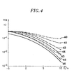
- the operation of the receiver of the invention has been simulated as part of the 8 kbit / s channel service on the uplink of the UMTS CDMA system.
- the data and control symbols are multiplexed respectively on the components in phase (I) and in quadrature (Q) of the transmitted modulated signal.
- the spreading factor of the control symbols was double that of the data symbols.
- N p 6 pilot symbols assumed to be grouped together at the rate of each power control period.
- the average power of the data symbols was assumed to be twice that of the control symbols. Average energy received E is therefore identical for all symbols received and checks:
- the terminal is supposed to move at speed 500 km / h and use a carrier frequency of 1.92 Ghz.
- the Doppler spread corresponding to these choices is 1.778 kHz.
- the performances of a receiver according to the invention in accordance with these assumptions were compared to those of two conventional receivers used in CDMA receivers.
- the first one uses the algorithm averaging estimate, which compensates for modulation suffered by the samples received corresponding to pilot symbols and takes the average of these as estimation of the multipath channel.
- the second uses the linear estimation algorithm which compensates also modulation of symbol samples pilots, but performs interpolation and / or linear extrapolation of the channel according to the criterion of minimum mean square error (MSEE).
- MSEE minimum mean square error
- the comparison is made through the evolution of the gross binary error rate (BER) (without taking into account error correction coding) for pilot symbols distributed or grouped using the three proposed channel estimation algorithms (depending on the invention, by averaging or by linear estimation).
- BER gross binary error rate
- the receiver according to the invention guarantees a gain in E / I 0 of the order of 3dB compared to the most favorable of the conventional receivers.
Landscapes
- Engineering & Computer Science (AREA)
- Computer Networks & Wireless Communication (AREA)
- Signal Processing (AREA)
- Mobile Radio Communication Systems (AREA)
- Circuits Of Receivers In General (AREA)
- Noise Elimination (AREA)
Claims (4)
- Empfänger für CDMA-Radiokommunikationssignale, wobei diese Signale ausgehend von Symbolen mit durch Pseudozufallssequenzen verbreitertem Spektrum erhalten wurden, und wobei sich die Signale dann folgend einer Mehrzahl von Bahnen ausbreiten, wobei dieser Empfänger umfasst:wobei dieser Empfänger dadurch gekennzeichnet ist, dass:Mittel (120, ..., 12 l , ..., 12L-1) zum Wiederherstellen von L verschiedenen Bahnen entsprechenden nicht verbreiterten Signalen für jedes Symbol,Mittel (140, ..., 14 l , ..., 14L-1) zum Berechnen von L Abschätzungen der L Bahnen,Demodulationsmittel (160, ..., 16 l , ..., 16L-1) zum Behandeln jedes der L nicht verbreiterten Signale mit Hilfe der L entsprechenden Abschätzungen zum Erhalten der Beiträge der L Bahnen,einen Addierer (18) zum Bilden der Summe dieser L Beiträge und zum Liefern einer Abschätzung des empfangenen Symbols,eine Entscheidungsschaltung (20) bezüglich des empfangenen Symbols ausgehend von dem Wert der durch den Addierer gelieferten Abschätzung,a) er Blöcke von N Symbolen behandelt, wobei jeder Block Datensymbole und Steuersymbole umfasst, wobei jedes Symbol durch den Rang k, den es in dem Block einnimmt, aufgefunden wird, wobei k von 0 bis N-1 geht,b) der Empfänger für jede durch einen Index ℓ, ℓ gehend von 0 bis L-1, auffindbare Bahn und für jeden Block einen Vektor Cℓ mit N Komponenten berücksichtigt, welche die Bahn während dieses Blocks charakterisiert,c) der Empfänger Mittel (30) zum Definieren einer Basis von Vektoren Bk umfasst, wobei diese Vektoren die N Eigenvektoren der Matrixsind, wobei jeder Vektor Cℓ bezüglich dieser Basis in Komponenten zerlegt ist, wobei die Koeffizienten dieser Zerlegung, genannt Gℓk, zufällige unabhängige Gaussvariablen bilden,
 d) die Koeffizienten Gℓk für jede Bahn ℓ einen Vektor Gℓ mit N Komponenten definieren, wobei die Abschätzungsmittel (14ℓ) ausgelegt sind, jeden Vektor Gℓ durch einen auf einem Abschätzungs-Maximierungs (AM)-Algorithmus, welcher auf einem Kriterium der maximalen Wahrscheinlichkeit a posteriori basiert, basierenden iterativen Prozess abzuschätzen.
 - Empfänger nach Anspruch 1, bei dem:a) der Ausgang des Addierers (18) auf die Abschätzmittel (14ℓ) zurückgeschleift ist,b) die Abschätzmittel (14ℓ) anfänglich () initialisiert sind, indem die in dem Block enthaltenen und als bekannt angenommenen Steuersymbole berücksichtigt werden, was es erlaubt, am Ausgang des Addierers eine erste Abschätzung für die in dem Block enthaltenen Datensymbole zu erhalten, wobei die Abschätzmittel (14ℓ) dann (...
 ,
, , ...) die am Ausgang des Addierers vorliegenden abgeschätzten Symbole berücksichtigen und die Abschätzmittel dann schließlich nach einer letzten Iteration (
 ) den quasioptimalen Wert (G (D) / ℓ) des Vektors Gℓ liefern.
- Verfahren zum Empfangen von CDMA-Radiokommunikationssignalen, wobei diese Signale ausgehend von Symbolen mit durch Pseudozufallssequenzen verbreitertem Spektrum erhalten wurden und diese Signale sich dann folgend einer Mehrzahl von Bahnen ausbreiten, wobei dieses Verfahren zum Empfangen die folgenden Schritte umfasst:wobei dieses Verfahren dadurch gekennzeichnet ist, dass:für jedes Symbol L werden nicht verbreiterte Signale entsprechend L verschiedenen Bahnen zurückgewonnen,L Abschätzungen der L Bahnen werden berechnet,jedes der L nicht verbreiterten Signale wird mit Hilfe der L entsprechenden Abschätzungen demoduliert, um die L Beiträge der Bahnen zu erhalten,die Summe dieser L Beiträge wird gebildet, was eine Abschätzung des empfangenen Symbols ergibt,ausgehend von dem Wert der erhaltenen Abschätzung wird eine Entscheidung betreffend das empfangene Symbol getroffen,a) Blöcke von N Symbolen behandelt werden, wobei jeder Block Datensymbole und Steuersymbole umfasst, wobei jedes Symbol durch den Rang k auffindbar ist, den es in dem Block einnimmt, wobei k von 0 bis N-1 geht,b) für jede Bahn, auffindbar durch einen Index ℓ, wobei ℓ von 0 bis L-1 geht, und für jeden Block ein Vektor Cℓ mit N Komponenten, welche die Bahn während dieses Blocks charakterisiert, in Betracht gezogen wird,c) die Matrixwelche N Bk genannte Eigenvektoren besitzt, betrachtet wird, und dass diese Eigenvektoren Bk als Basis verwendet werden, jeder Vektor Cℓ bezüglich dieser Basis in Komponenten zerlegt wird, wobei die Gℓ k genannten Koeffizienten der Zerlegung zufällige unabhängige Gaussche Variablen darstellen,
 d) die Koeffizienten Gℓk für jede Bahn ℓ einen Vektor Gℓ mit N Komponenten definieren und jeder Vektor Gℓ durch einen auf einen Abschätzungs-Maximierungs(AM)-Algorithmus, welcher auf einem Kriterium der maximalen Wahrscheinlichkeit a posteriori basiert, basierenden iterativen Algorithmus abgeschätzt wird.
 - Verfahren nach Anspruch 3, bei dem der iterative Prozess anfänglich initialisiert wird, indem die in dem Block enthaltenen und als bekannt angenommenen Steuersymbole berücksichtigt werden, was es erlaubt, eine erste Abschätzung für die in dem Block enthaltenen Datensymbole zu erhalten, wobei der iterative Prozess dann alle Symbole des Blocks entsprechend dieser ersten Abschätzung berücksichtigt, was es erlaubt, eine zweite Abschätzung der Symbole des Blocks zu erhalten, usw., bis zum Erhalten einer befriedigenden Abschätzung für Gℓ, welche für die Demodulierung benutzt wird.
Applications Claiming Priority (3)
| Application Number | Priority Date | Filing Date | Title |
|---|---|---|---|
| FR9810578 | 1998-08-20 | ||
| FR9810578A FR2782585B1 (fr) | 1998-08-20 | 1998-08-20 | Recepteur en rateau iteratif et procede de reception correspondant |
| PCT/FR1999/002013 WO2000011799A1 (fr) | 1998-08-20 | 1999-08-19 | Recepteur en rateau iteratif et procede de reception correspondant |
Publications (2)
| Publication Number | Publication Date |
|---|---|
| EP1105975A1 EP1105975A1 (de) | 2001-06-13 |
| EP1105975B1 true EP1105975B1 (de) | 2003-10-29 |
Family
ID=9529793
Family Applications (1)
| Application Number | Title | Priority Date | Filing Date |
|---|---|---|---|
| EP99939481A Expired - Lifetime EP1105975B1 (de) | 1998-08-20 | 1999-08-19 | Iterativer rake-empfänger und entsprechendes empfangsverfahren |
Country Status (9)
| Country | Link |
|---|---|
| US (1) | US6674740B1 (de) |
| EP (1) | EP1105975B1 (de) |
| JP (1) | JP4142255B2 (de) |
| CN (1) | CN1130845C (de) |
| AR (1) | AR025266A1 (de) |
| DE (1) | DE69912448T2 (de) |
| ES (1) | ES2209479T3 (de) |
| FR (1) | FR2782585B1 (de) |
| WO (1) | WO2000011799A1 (de) |
Families Citing this family (11)
| Publication number | Priority date | Publication date | Assignee | Title |
|---|---|---|---|---|
| JP2001203669A (ja) * | 2000-01-24 | 2001-07-27 | Matsushita Electric Ind Co Ltd | 無線基地局装置及び無線通信方法 |
| US6901120B2 (en) * | 2000-12-06 | 2005-05-31 | Telefonaktiebolaget L M Ericsson (Publ) | Method and apparatus for iterative parameter estimation |
| US20020129159A1 (en) | 2001-03-09 | 2002-09-12 | Michael Luby | Multi-output packet server with independent streams |
| JP3831229B2 (ja) * | 2001-10-31 | 2006-10-11 | 富士通株式会社 | 伝搬路特性推定装置 |
| US7308232B2 (en) * | 2002-06-21 | 2007-12-11 | Lucent Technologies Inc. | Method and apparatus for estimating a channel based on channel statistics |
| EP1447927A1 (de) * | 2003-02-17 | 2004-08-18 | France Telecom | Vorrichtung und Verfahren zur Signalverarbeitung |
| KR101175904B1 (ko) * | 2003-09-26 | 2012-08-21 | 인터디지탈 테크날러지 코포레이션 | 무선 통신 전송 파워용 이득 팩터들의 판정을 위한 장치 및 방법 |
| US7298799B1 (en) | 2004-03-08 | 2007-11-20 | Redpine Signals, Inc. | All-tap fractionally spaced, serial rake combiner apparatus and method |
| US7233777B2 (en) * | 2004-08-31 | 2007-06-19 | L-3 Integrated Systems Company | Separation of AM cochannel signals in an overloaded signal environment |
| US7957453B2 (en) * | 2008-03-20 | 2011-06-07 | Raytheon Company | Method for operating a rake receiver |
| EP2340661A1 (de) * | 2008-10-24 | 2011-07-06 | NEC Corporation | Gerät und verfahren zur messung der doppler-verbreiterung in einem mobilen kommunikationsendgerät |
Family Cites Families (11)
| Publication number | Priority date | Publication date | Assignee | Title |
|---|---|---|---|---|
| US5442661A (en) * | 1993-08-13 | 1995-08-15 | Motorola Inc. | Path gain estimation in a receiver |
| KR950035142A (ko) * | 1994-03-10 | 1995-12-30 | 가나미야지 준 | 수신장치, 기지국 수신 시스템 및 이동국 수신시스템 |
| JP2974274B2 (ja) * | 1994-05-12 | 1999-11-10 | エヌ・ティ・ティ移動通信網株式会社 | 送信電力制御方法および送信電力制御装置 |
| FI98108C (fi) * | 1995-05-17 | 1997-04-10 | Nokia Mobile Phones Ltd | Menetelmä yhteyden laadun arvioimiseksi ja vastaanotin |
| US5790588A (en) * | 1995-06-07 | 1998-08-04 | Ntt Mobile Communications Network, Inc. | Spread spectrum transmitter and receiver employing composite spreading codes |
| US5671221A (en) * | 1995-06-14 | 1997-09-23 | Sharp Microelectronics Technology, Inc. | Receiving method and apparatus for use in a spread-spectrum communication system |
| FR2737362B1 (fr) * | 1995-07-25 | 1997-10-10 | Matra Communication | Procede de selection des retards de propagation retenus pour recevoir des messages transmis par radiocommunication a etalement de spectre |
| US5692006A (en) * | 1995-07-31 | 1997-11-25 | Qualcomm Incorporated | Adaptive despreader |
| US5737327A (en) * | 1996-03-29 | 1998-04-07 | Motorola, Inc. | Method and apparatus for demodulation and power control bit detection in a spread spectrum communication system |
| FR2782587B1 (fr) * | 1998-08-20 | 2000-09-22 | France Telecom | Procedes de communications numeriques amrc a repartition des symboles de reference |
| FI106897B (fi) * | 1998-09-14 | 2001-04-30 | Nokia Networks Oy | RAKE-vastaanotin |
-
1998
- 1998-08-20 FR FR9810578A patent/FR2782585B1/fr not_active Expired - Fee Related
-
1999
- 1999-08-13 US US09/373,626 patent/US6674740B1/en not_active Expired - Fee Related
- 1999-08-19 JP JP2000566960A patent/JP4142255B2/ja not_active Expired - Fee Related
- 1999-08-19 WO PCT/FR1999/002013 patent/WO2000011799A1/fr active IP Right Grant
- 1999-08-19 CN CN99809793.4A patent/CN1130845C/zh not_active Expired - Fee Related
- 1999-08-19 ES ES99939481T patent/ES2209479T3/es not_active Expired - Lifetime
- 1999-08-19 EP EP99939481A patent/EP1105975B1/de not_active Expired - Lifetime
- 1999-08-19 DE DE69912448T patent/DE69912448T2/de not_active Expired - Lifetime
- 1999-08-20 AR ARP990104195A patent/AR025266A1/es unknown
Also Published As
| Publication number | Publication date |
|---|---|
| AR025266A1 (es) | 2002-11-20 |
| WO2000011799A1 (fr) | 2000-03-02 |
| DE69912448D1 (de) | 2003-12-04 |
| FR2782585B1 (fr) | 2000-09-22 |
| DE69912448T2 (de) | 2004-07-29 |
| CN1130845C (zh) | 2003-12-10 |
| FR2782585A1 (fr) | 2000-02-25 |
| JP2002523962A (ja) | 2002-07-30 |
| EP1105975A1 (de) | 2001-06-13 |
| JP4142255B2 (ja) | 2008-09-03 |
| US6674740B1 (en) | 2004-01-06 |
| CN1320306A (zh) | 2001-10-31 |
| ES2209479T3 (es) | 2004-06-16 |
Similar Documents
| Publication | Publication Date | Title |
|---|---|---|
| EP1212872B1 (de) | Ofdm-empfänger mit iterativer kanalschätzung und zugehöriges verfahren | |
| EP0867079B1 (de) | Verfahren und anordnung zur entzerrung von mehrfachantennensignalen für mehrfachelementempfang in gegenwart von störungen und mehrwegausbreitungen | |
| EP1325600A1 (de) | Verfahren zur optimalen schätzung eines ausbreitungskanals unter ausschliesslicher verwendung von pilotsymbolen und entsprechender schätzer | |
| FR2706709A1 (fr) | Procédé de synchronisation pour des communications radiotéléphoniques à accès multiple à répartition par codes. | |
| EP1105975B1 (de) | Iterativer rake-empfänger und entsprechendes empfangsverfahren | |
| EP1185004A1 (de) | Verfahren zum gemeinsamen Einfallswinkel- und Kanalschätzung | |
| EP1260071B1 (de) | Verfahren und vorrichtung für kanalschäztung | |
| EP1187366B1 (de) | Adaptiver uni-modularer CDMA-Empfänger | |
| EP1184997A1 (de) | Verfahren zur Mehrbenutzerdetektion | |
| EP0669729B1 (de) | Verfahren zur Durchführung von einer mehrkanalen Entzerrung in einem Rundfunkempfänger bei Störungen und Mehrwegeausbreitung | |
| EP0820157B1 (de) | Verfahren zur digitalen Differenzialdemodulation | |
| WO2000076160A1 (fr) | Procede de communications radiomobiles amrt iteratif | |
| EP1265374B1 (de) | Verfahren und Vorrichtung zur Signalverarbeitung in einem Spreizspektrum Funkkommunikationsempfänger | |
| EP0849889B1 (de) | Verfahren zum Mehrwegesignalempfang | |
| FR2803467A1 (fr) | Methode d'estimation d'un canal de transmission ou de telecommunication | |
| EP1184996B1 (de) | Ein nichtkoheräntes DP-MOK Empfangsverfahren mit Mehrwegkombination und Empfänger dafür | |
| WO2007028917A2 (fr) | Estimation iterative de canal de mimo dans un reseau cdma | |
| EP1288675A1 (de) | Verfahren und Vorrichtung zur Schätzung der Geschwindigkeit eines mobilen Endgeräts, insbesondere eines zellularen Mobiltelefons | |
| EP1283605A1 (de) | Verfahren zur Erhöhung der Datenrate in einem Kommunikationssystem mit N Sendern und M Empfängern | |
| EP1714511B1 (de) | Verfahren zur optimierung der planung in einem cdma-kommunikationssystem | |
| EP1240759A1 (de) | Vorrichtungen zur funkkanals-und demodulationsschätzung | |
| EP1693969B1 (de) | CDMA-Empfangsverfahren mit paralleler Interferenzunterdrückung, entsprechende Stufe und Empfänger | |
| WO2007031691A1 (fr) | Procede et dispositif de configuration d'un recepteur dans un dispositif de communication. | |
| WO2006131665A1 (fr) | Dispositif et procede de selection d'un recepteur en fonction de l'environnement |
Legal Events
| Date | Code | Title | Description |
|---|---|---|---|
| PUAI | Public reference made under article 153(3) epc to a published international application that has entered the european phase |
Free format text: ORIGINAL CODE: 0009012 |
|
| 17P | Request for examination filed |
Effective date: 20010130 |
|
| AK | Designated contracting states |
Kind code of ref document: A1 Designated state(s): AT BE CH CY DE DK ES FI FR GB GR IE IT LI LU MC NL PT SE |
|
| GRAH | Despatch of communication of intention to grant a patent |
Free format text: ORIGINAL CODE: EPIDOS IGRA |
|
| GRAS | Grant fee paid |
Free format text: ORIGINAL CODE: EPIDOSNIGR3 |
|
| GRAA | (expected) grant |
Free format text: ORIGINAL CODE: 0009210 |
|
| AK | Designated contracting states |
Kind code of ref document: B1 Designated state(s): DE ES FI GB IT SE |
|
| PG25 | Lapsed in a contracting state [announced via postgrant information from national office to epo] |
Ref country code: FI Free format text: LAPSE BECAUSE OF FAILURE TO SUBMIT A TRANSLATION OF THE DESCRIPTION OR TO PAY THE FEE WITHIN THE PRESCRIBED TIME-LIMIT Effective date: 20031029 |
|
| REG | Reference to a national code |
Ref country code: GB Ref legal event code: FG4D Free format text: NOT ENGLISH |
|
| REG | Reference to a national code |
Ref country code: IE Ref legal event code: FG4D Free format text: FRENCH |
|
| REF | Corresponds to: |
Ref document number: 69912448 Country of ref document: DE Date of ref document: 20031204 Kind code of ref document: P |
|
| PG25 | Lapsed in a contracting state [announced via postgrant information from national office to epo] |
Ref country code: SE Free format text: LAPSE BECAUSE OF FAILURE TO SUBMIT A TRANSLATION OF THE DESCRIPTION OR TO PAY THE FEE WITHIN THE PRESCRIBED TIME-LIMIT Effective date: 20040129 |
|
| GBT | Gb: translation of ep patent filed (gb section 77(6)(a)/1977) |
Effective date: 20040204 |
|
| REG | Reference to a national code |
Ref country code: ES Ref legal event code: FG2A Ref document number: 2209479 Country of ref document: ES Kind code of ref document: T3 |
|
| REG | Reference to a national code |
Ref country code: IE Ref legal event code: FD4D |
|
| PLBE | No opposition filed within time limit |
Free format text: ORIGINAL CODE: 0009261 |
|
| STAA | Information on the status of an ep patent application or granted ep patent |
Free format text: STATUS: NO OPPOSITION FILED WITHIN TIME LIMIT |
|
| 26N | No opposition filed |
Effective date: 20040730 |
|
| PGFP | Annual fee paid to national office [announced via postgrant information from national office to epo] |
Ref country code: GB Payment date: 20110728 Year of fee payment: 13 Ref country code: ES Payment date: 20110805 Year of fee payment: 13 Ref country code: DE Payment date: 20110803 Year of fee payment: 13 |
|
| PGFP | Annual fee paid to national office [announced via postgrant information from national office to epo] |
Ref country code: IT Payment date: 20110723 Year of fee payment: 13 |
|
| GBPC | Gb: european patent ceased through non-payment of renewal fee |
Effective date: 20120819 |
|
| PG25 | Lapsed in a contracting state [announced via postgrant information from national office to epo] |
Ref country code: IT Free format text: LAPSE BECAUSE OF NON-PAYMENT OF DUE FEES Effective date: 20120819 |
|
| PG25 | Lapsed in a contracting state [announced via postgrant information from national office to epo] |
Ref country code: DE Free format text: LAPSE BECAUSE OF NON-PAYMENT OF DUE FEES Effective date: 20130301 Ref country code: GB Free format text: LAPSE BECAUSE OF NON-PAYMENT OF DUE FEES Effective date: 20120819 |
|
| REG | Reference to a national code |
Ref country code: DE Ref legal event code: R119 Ref document number: 69912448 Country of ref document: DE Effective date: 20130301 |
|
| REG | Reference to a national code |
Ref country code: ES Ref legal event code: FD2A Effective date: 20131030 |
|
| PG25 | Lapsed in a contracting state [announced via postgrant information from national office to epo] |
Ref country code: ES Free format text: LAPSE BECAUSE OF NON-PAYMENT OF DUE FEES Effective date: 20120820 |