EP1184832A1 - Bildschirm, der betätigbar ist in einem Energiesparmodus mit reduziertem Impuls-Leistungsverbrauch des Heizwendels - Google Patents
Bildschirm, der betätigbar ist in einem Energiesparmodus mit reduziertem Impuls-Leistungsverbrauch des Heizwendels Download PDFInfo
- Publication number
- EP1184832A1 EP1184832A1 EP00307430A EP00307430A EP1184832A1 EP 1184832 A1 EP1184832 A1 EP 1184832A1 EP 00307430 A EP00307430 A EP 00307430A EP 00307430 A EP00307430 A EP 00307430A EP 1184832 A1 EP1184832 A1 EP 1184832A1
- Authority
- EP
- European Patent Office
- Prior art keywords
- power
- heater
- manager circuit
- power manager
- coupled
- Prior art date
- Legal status (The legal status is an assumption and is not a legal conclusion. Google has not performed a legal analysis and makes no representation as to the accuracy of the status listed.)
- Withdrawn
Links
Images


Classifications
-
- G—PHYSICS
- G09—EDUCATION; CRYPTOGRAPHY; DISPLAY; ADVERTISING; SEALS
- G09G—ARRANGEMENTS OR CIRCUITS FOR CONTROL OF INDICATING DEVICES USING STATIC MEANS TO PRESENT VARIABLE INFORMATION
- G09G1/00—Control arrangements or circuits, of interest only in connection with cathode-ray tube indicators; General aspects or details, e.g. selection emphasis on particular characters, dashed line or dotted line generation; Preprocessing of data
- G09G1/06—Control arrangements or circuits, of interest only in connection with cathode-ray tube indicators; General aspects or details, e.g. selection emphasis on particular characters, dashed line or dotted line generation; Preprocessing of data using single beam tubes, e.g. three-dimensional or perspective representation, rotation or translation of display pattern, hidden lines, shadows
- G09G1/14—Control arrangements or circuits, of interest only in connection with cathode-ray tube indicators; General aspects or details, e.g. selection emphasis on particular characters, dashed line or dotted line generation; Preprocessing of data using single beam tubes, e.g. three-dimensional or perspective representation, rotation or translation of display pattern, hidden lines, shadows the beam tracing a pattern independent of the information to be displayed, this latter determining the parts of the pattern rendered respectively visible and invisible
- G09G1/16—Control arrangements or circuits, of interest only in connection with cathode-ray tube indicators; General aspects or details, e.g. selection emphasis on particular characters, dashed line or dotted line generation; Preprocessing of data using single beam tubes, e.g. three-dimensional or perspective representation, rotation or translation of display pattern, hidden lines, shadows the beam tracing a pattern independent of the information to be displayed, this latter determining the parts of the pattern rendered respectively visible and invisible the pattern of rectangular co-ordinates extending over the whole area of the screen, i.e. television type raster
- G09G1/165—Details of a display terminal using a CRT, the details relating to the control arrangement of the display terminal and to the interfaces thereto
-
- G—PHYSICS
- G09—EDUCATION; CRYPTOGRAPHY; DISPLAY; ADVERTISING; SEALS
- G09G—ARRANGEMENTS OR CIRCUITS FOR CONTROL OF INDICATING DEVICES USING STATIC MEANS TO PRESENT VARIABLE INFORMATION
- G09G1/00—Control arrangements or circuits, of interest only in connection with cathode-ray tube indicators; General aspects or details, e.g. selection emphasis on particular characters, dashed line or dotted line generation; Preprocessing of data
- G09G1/005—Power supply circuits
-
- G—PHYSICS
- G09—EDUCATION; CRYPTOGRAPHY; DISPLAY; ADVERTISING; SEALS
- G09G—ARRANGEMENTS OR CIRCUITS FOR CONTROL OF INDICATING DEVICES USING STATIC MEANS TO PRESENT VARIABLE INFORMATION
- G09G2330/00—Aspects of power supply; Aspects of display protection and defect management
- G09G2330/02—Details of power systems and of start or stop of display operation
- G09G2330/021—Power management, e.g. power saving
Definitions
- the invention relates to a computer display monitor, more particularly to a computer display monitor that is operable in a power-saving mode.
- a computer conveys video signals, such as RGB signals, and horizontal and vertical synchronization (HSYNC, VSYNC) signals to a computer display monitor.
- video signals such as RGB signals
- horizontal and vertical synchronization (HSYNC, VSYNC) signals to a computer display monitor.
- a microprocessor of the computer detects a period of inactivity on peripheral input devices thereof, such as a mouse or keyboard, the computer will cease to provide at least one of the synchronization signals to the monitor.
- a video monitor with a power manager circuit which causes the video monitor to assume at least two reduced-power states in response to detection of computer inactivity.
- the video monitor has a port for receiving signals, such as RGB color signals and HSYNC and VSYNC signals, from a computer.
- a video circuit receives the RGB color signals, whereas a micro-controller receives the HSYNC and VSYNC signals from the port.
- the HSYNC and VSYNC signals are subsequently received by the video circuit via the micro-controller.
- the micro-controller is further coupled to the video circuit via first and second signal lines.
- both the first and second signal lines are in an inactive state. Power is supplied to all circuits of the monitor at this time.
- the first signal line changes to an active state when the micro-controller detects the absence of the VSYNC signal from the computer.
- the second signal line changes to an active state when the micro-controller detects the absence of the HSYNC signal from the computer. Both the first and second signal lines are reset to the inactive state when the HSYNC and VSYNC signals are restored.
- the monitor When the first signal line is in the active state, power to all circuits in the monitor, except the micro-controller, the port and the video circuit, is cut off.
- the monitor is operating in a first standby mode at this time. In the first standby mode, a longer warm-up time is required to resume normal operation of the monitor, which can inconvenience the user.
- the power consumption of the monitor in the first standby mode is typically less than 5 watts.
- the monitor When the second signal line is in the active state, power to all circuits in the monitor, except the micro-controller, the port, the video circuit and the filament heater of the cathode ray tube, is cut off.
- the monitor is operating in a second standby mode at this time. In the second standby mode, a shorter warm-up time, typically 5 seconds or less, is required to resume normal operation of the monitor because the cathode ray tube is maintained at the operating temperature.
- inefficient power use occurs because the power consumption of the monitor in the second standby mode is much greater than that when the monitor operates in the first standby mode.
- the object of the present invention is to provide a display monitor that is operable in a single power-saving mode, wherein the power consumption of the monitor can be minimized, and wherein resumption of normal operation of the monitor from the power-saving mode can be accomplished within a short amount of time.
- a display monitor includes a cathode ray tube with a filament heater, a power manager circuit coupled to the heater and adapted to be coupled to a power source, and a detector coupled to the power manager circuit and adapted to detect incoming signals, including synchronization signals, conveyed by a computer.
- the detector issues a command to the power manager circuit upon detecting absence of at least one of the incoming signals received from the computer.
- the power manager circuit operates in a power-saving mode to reduce power consumption of the monitor in response to the command from the detector.
- the power manager circuit reduces operating duty cycle of the heater to a predetermined value less than 100% but greater than 0% in order to maintain temperature of the heater to between ambient temperature and operating temperature of the heater at 100% operating duty cycle when the power manager circuit operates in the power-saving mode.
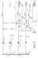
- the preferred embodiment of a display monitor comprises a known power rectifier 11 adapted to be connected to a commercial AC power source and to generate DC power, a known power supplying circuit 12 coupled to the power rectifier 11 so as to receive the DC power therefrom and so as to generate operating voltages and currents that are supplied to power-using circuitry of the display monitor, a known cathode ray tube with a filament heater 13 and horizontal and vertical deflection circuits 14, and a known control circuit (not shown) including a video signal processing circuit (not shown) for processing incoming signals conveyed by a computer (not shown).
- the incoming signals include video signals, such as RGB color signals, and horizontal and vertical synchronization (HSYNC, VSYNC) signals.
- the video signal processing circuit is adapted to perform brightness, contrast and color adjustment in a conventional manner.
- the control circuit further includes a video output circuit (not shown) for driving the cathode ray tube in a conventional manner.
- a micro-controller 15 is coupled to the power supplying circuit 12, and controls the operations of the various circuits of the display monitor. In general, a major portion of the total power consumed by the display monitor is attributed to the deflection circuits 14 and the heater 13. The invention is thus concerned primarily with the management of the power consumed by the deflection circuits 14 and the heater 13.
- the display monitor further comprises a detector 150 embedded in the micro-controller 15, and a power manager circuit 4 coupled to the heater 13, the deflection circuits 14 and the power supplying circuit 12.
- the detector 150 is coupled to the power manager circuit 4, and is adapted to detect the HSYNC and VSYNC signals conveyed by the computer (not shown).
- the detector 150 provides first and second control signals MCA0, MCA1 to the power manager circuit 4 in response to the HSYNC and VSYNC signals received from the computer.
- both the first and second control signals MCA0, MCA1 have a high logic state, and are used to maintain operation of the monitor in a normal operating mode.
- the first control signal MCA0 is in the form of a pulse train signal with alternating high and low logic states, as shown in Figure 3, whereas the second control signal MCA1 has a low logic state.
- the monitor is controlled to operate in a sole power-saving mode at this time.
- the power manager circuit 4 includes first and second switches 2, 3 whose switching actions are controlled by the first and second control signals MCA0, MCA1, respectively.
- the first switch 2 interconnects the power supplying circuit 12 and the heater 13.
- the first control signal MCA0 is at a high logic state
- the first switch 2 makes electrical connection between the power supplying circuit 12 and the heater 13, thereby enabling the supply of electric power to the heater 13.
- the first control signal MCA0 is at a low logic state
- the first switch 2 breaks electrical connection between the power supplying circuit 12 and the heater 13, thereby cutting off the supply of electric power to the heater 13.
- the first switch 2 when the first control signal MCA0 is in the form of the pulse train signal shown in Figure 3, the first switch 2 is enabled so that electric power is intermittently supplied to the heater 13 during operation of the monitor in the power-saving mode, as best illustrated in Figure 4.
- the operating duty cycle of the heater 13 is thus reduced to a predetermined value less than 100% but greater than 0% in order to maintain the heater 13 at a pre-heated condition with a temperature that is between ambient temperature and operating temperature of the heater 13 at 100% operating duty cycle.
- the predetermined value of the operating duty cycle of the heater 13 corresponds to the duty cycle of the first control signal MCA0. The heater 13 therefore consumes less power in the power-saving mode than that when the monitor operates in the normal operating mode.
- the first switch 2 includes two transistors Q942, Q943 and two resistors R950, R951.
- the base of the transistor Q943 receives the first control signal MCA0.
- the collector of the transistor Q943 is connected to the base of the transistor Q942 via the resistor R951.
- the base and emitter of the transistor Q942 are interconnected via the resistor R950.
- the emitter of the transistor Q943 is grounded.
- the collector of the transistor Q942 is connected to the heater 13, whereas the emitter of the transistor Q942 is connected to the power supplying circuit 12.
- the second switch 3 interconnects the power supplying circuit 12 and the deflection circuits 14.
- the second switch 3 makes electrical connection between the power supplying circuit 12 and the deflection circuits 14, thereby enabling the supply of electric power to the deflection circuits 14.
- the second switch 3 breaks electrical connection between the power supplying circuit 12 and the deflection circuits 14, thereby cutting off the supply of electric power to the deflection circuits 14.
- the second switch 3 includes two transistors Q940, Q941 and two resistors R945, R946.
- the base of the transistor Q941 receives the second control signal MCA1.
- the collector of the transistor Q941 is connected to the base of the transistor Q940 via the resistor R946.
- the base and emitter of the transistor Q940 are interconnected via the resistor R945.
- the emitter of the transistor Q941 is grounded.
- the collector of the transistor Q940 is connected to the deflection circuits 14, whereas the emitter of the transistor Q940 is connected to the power supplying circuit 12.
- the transistors Q941, Q940 When the second logic signal MCA1 is at the high logic state, the transistors Q941, Q940 conduct, and electric power is supplied to the deflection circuits 14 via the transistor Q940. Accordingly, when the second logic signal MCA1 is at the low logic state, the transistors Q941, Q940 are cut-off, and the supply of electric power to the deflection circuits 14 is interrupted.
- the operating duty cycle of the heater 13 is lower than 100%, and the average operating voltage of the heater 13 is thus less than the full operating voltage.
- the operating duty cycle of the heater 13 is also 50% (see Figure 4).
- the full operating voltage (V1) of the heater 13 is 5 volts
- the average operating voltage (V2) of the heater 13 in the power-saving mode is 2.5 volts. Therefore, the heater 13 is maintained at a pre-heated condition such that the warm-up time required to resume normal operation of the monitor may take as little as 3 seconds.
- the average operating voltage of the heater 13 in the power-saving mode depends on the full operating voltage and the operating duty cycle thereof. Therefore, by adjusting the operating duty cycle of the heater 13, the average operating voltage of the heater 13 in the power-saving mode can be adjusted as well to reduce the power consumed by the monitor to below 5 watts without prolonging undesirably the warm-up time required to resume normal operation of the monitor from the power-saving mode.
- the first and second switches 2, 3 are enabled via the first and second control signals MCA0, MCA1 to connect electrically the heater 13 and the deflection circuits 14 with the power supplying circuit 12.
- the monitor Upon detection by the detector 150 of the absence of at least one of the HSYNC and VSYNC signals, the monitor operates in the sole power-saving mode, wherein the first switch 2 is enabled via the first control signal MCA0 to supply electric power intermittently to the heater 13 and thus lower the average operating voltage of the heater 13 so as to maintain the latter at the pre-heated condition in order to ensure a relatively short warm-up time for resuming normal operation of the monitor from the power-saving mode, and wherein the second switch 3 is enabled via the second control signal MCA1 to break electrical connection between the deflection circuits 14 and the power supplying circuit 12.
Priority Applications (1)
| Application Number | Priority Date | Filing Date | Title |
|---|---|---|---|
| EP00307430A EP1184832A1 (de) | 2000-08-30 | 2000-08-30 | Bildschirm, der betätigbar ist in einem Energiesparmodus mit reduziertem Impuls-Leistungsverbrauch des Heizwendels |
Applications Claiming Priority (1)
| Application Number | Priority Date | Filing Date | Title |
|---|---|---|---|
| EP00307430A EP1184832A1 (de) | 2000-08-30 | 2000-08-30 | Bildschirm, der betätigbar ist in einem Energiesparmodus mit reduziertem Impuls-Leistungsverbrauch des Heizwendels |
Publications (1)
| Publication Number | Publication Date |
|---|---|
| EP1184832A1 true EP1184832A1 (de) | 2002-03-06 |
Family
ID=8173230
Family Applications (1)
| Application Number | Title | Priority Date | Filing Date |
|---|---|---|---|
| EP00307430A Withdrawn EP1184832A1 (de) | 2000-08-30 | 2000-08-30 | Bildschirm, der betätigbar ist in einem Energiesparmodus mit reduziertem Impuls-Leistungsverbrauch des Heizwendels |
Country Status (1)
| Country | Link |
|---|---|
| EP (1) | EP1184832A1 (de) |
Citations (5)
| Publication number | Priority date | Publication date | Assignee | Title |
|---|---|---|---|---|
| GB2264848A (en) * | 1992-03-02 | 1993-09-08 | Icl Personal Systems Oy | Video display with remote power switching. |
| JPH06165090A (ja) * | 1992-11-20 | 1994-06-10 | Fujitsu General Ltd | Crtのヒータ回路 |
| US5648799A (en) * | 1992-12-02 | 1997-07-15 | Elonex I.P. Holdings, Ltd. | Low-power-consumption monitor standby system |
| JPH09247577A (ja) * | 1996-03-12 | 1997-09-19 | Funai Electric Co Ltd | 映像装置 |
| US5870086A (en) * | 1996-08-14 | 1999-02-09 | Samsung Electronics Co., Ltd. | Power saving display device and method for controlling power thereof |
-
2000
- 2000-08-30 EP EP00307430A patent/EP1184832A1/de not_active Withdrawn
Patent Citations (5)
| Publication number | Priority date | Publication date | Assignee | Title |
|---|---|---|---|---|
| GB2264848A (en) * | 1992-03-02 | 1993-09-08 | Icl Personal Systems Oy | Video display with remote power switching. |
| JPH06165090A (ja) * | 1992-11-20 | 1994-06-10 | Fujitsu General Ltd | Crtのヒータ回路 |
| US5648799A (en) * | 1992-12-02 | 1997-07-15 | Elonex I.P. Holdings, Ltd. | Low-power-consumption monitor standby system |
| JPH09247577A (ja) * | 1996-03-12 | 1997-09-19 | Funai Electric Co Ltd | 映像装置 |
| US5870086A (en) * | 1996-08-14 | 1999-02-09 | Samsung Electronics Co., Ltd. | Power saving display device and method for controlling power thereof |
Non-Patent Citations (2)
| Title |
|---|
| PATENT ABSTRACTS OF JAPAN vol. 018, no. 488 (E - 1605) 12 September 1994 (1994-09-12) * |
| PATENT ABSTRACTS OF JAPAN vol. 1998, no. 01 30 January 1998 (1998-01-30) * |
Similar Documents
| Publication | Publication Date | Title |
|---|---|---|
| EP0590837B1 (de) | Steuerungschaltung für Stromversorgung eines Kathodenstrahlröhrenanzeigegeräts und entsprechendes Verfahren | |
| US6345364B1 (en) | Power supply of display apparatus with universal serial bus device | |
| KR100224085B1 (ko) | 전원절약형 디스플레이장치 및 전원제어 방법 | |
| KR101744927B1 (ko) | 슬립 모드에서의 최대 절전형 모니터 제어 방법 | |
| US6362541B1 (en) | System and method for reduced standby power consumption in a display device | |
| KR100234423B1 (ko) | 컴퓨터 주변기기의 전원제어 장치 및 방법 | |
| KR101759345B1 (ko) | 딥 슬립 모드를 지원하는 절전형 모니터의 제어 장치 및 방법 | |
| US5944830A (en) | Reducing power consumption in monitor by switching off heater power in power-off mode | |
| MXPA99010360A (es) | Circuito y metodo de ahorro de energia de monitor. | |
| US6515716B1 (en) | Terminal device, accounting system and data processing method | |
| EP0897562B1 (de) | Videoanzeigegerät | |
| EP1184832A1 (de) | Bildschirm, der betätigbar ist in einem Energiesparmodus mit reduziertem Impuls-Leistungsverbrauch des Heizwendels | |
| US20020169992A1 (en) | Device for reducing power consumption of a monitor and the method therof | |
| US6769070B1 (en) | Standby circuit for digital display monitor | |
| AU670987B2 (en) | Power saving apparatus for a monitor and method therefor | |
| KR100248289B1 (ko) | 초절전형 모니터의 전원회로 | |
| JPH0934600A (ja) | モニタパワーセーブ回路及びモニタ装置 | |
| KR0135908Y1 (ko) | 모니터의 오프모드 직접 제어회로 | |
| KR102051949B1 (ko) | Sync 신호 제어를 활용한 에너지 절감형 모니터장치의 제어방법 | |
| KR100394005B1 (ko) | 모니터의 전력 제어 방법 | |
| JP2004163455A (ja) | ディスプレイ装置および節電制御装置 | |
| KR0182927B1 (ko) | 모니터 일체형 컴퓨터의 절전형 회로장치 및 방법 | |
| JP2000358368A (ja) | スイッチング電源装置 | |
| KR0151490B1 (ko) | 모니터의 전원 안정화 회로 | |
| KR100287846B1 (ko) | 모니터의 디피앰 모드 소비전력 절감장치 |
Legal Events
| Date | Code | Title | Description |
|---|---|---|---|
| PUAI | Public reference made under article 153(3) epc to a published international application that has entered the european phase |
Free format text: ORIGINAL CODE: 0009012 |
|
| 17P | Request for examination filed |
Effective date: 20000929 |
|
| AK | Designated contracting states |
Kind code of ref document: A1 Designated state(s): AT BE CH CY DE DK ES FI FR GB GR IE IT LI LU MC NL PT SE |
|
| AX | Request for extension of the european patent |
Free format text: AL;LT;LV;MK;RO;SI |
|
| AKX | Designation fees paid |
Free format text: AT BE CH CY DE DK ES FI FR GB GR IE IT LI LU MC NL PT SE |
|
| STAA | Information on the status of an ep patent application or granted ep patent |
Free format text: STATUS: THE APPLICATION IS DEEMED TO BE WITHDRAWN |
|
| 18D | Application deemed to be withdrawn |
Effective date: 20040302 |