EP1184657A2 - Method for evaluating a delayed fracture of a steel member - Google Patents
Method for evaluating a delayed fracture of a steel member Download PDFInfo
- Publication number
- EP1184657A2 EP1184657A2 EP01307251A EP01307251A EP1184657A2 EP 1184657 A2 EP1184657 A2 EP 1184657A2 EP 01307251 A EP01307251 A EP 01307251A EP 01307251 A EP01307251 A EP 01307251A EP 1184657 A2 EP1184657 A2 EP 1184657A2
- Authority
- EP
- European Patent Office
- Prior art keywords
- stress
- steel member
- weibull
- steel
- finding
- Prior art date
- Legal status (The legal status is an assumption and is not a legal conclusion. Google has not performed a legal analysis and makes no representation as to the accuracy of the status listed.)
- Withdrawn
Links
Images


Classifications
-
- C—CHEMISTRY; METALLURGY
- C22—METALLURGY; FERROUS OR NON-FERROUS ALLOYS; TREATMENT OF ALLOYS OR NON-FERROUS METALS
- C22C—ALLOYS
- C22C38/00—Ferrous alloys, e.g. steel alloys
- C22C38/18—Ferrous alloys, e.g. steel alloys containing chromium
- C22C38/22—Ferrous alloys, e.g. steel alloys containing chromium with molybdenum or tungsten
-
- G—PHYSICS
- G01—MEASURING; TESTING
- G01N—INVESTIGATING OR ANALYSING MATERIALS BY DETERMINING THEIR CHEMICAL OR PHYSICAL PROPERTIES
- G01N3/00—Investigating strength properties of solid materials by application of mechanical stress
-
- C—CHEMISTRY; METALLURGY
- C22—METALLURGY; FERROUS OR NON-FERROUS ALLOYS; TREATMENT OF ALLOYS OR NON-FERROUS METALS
- C22C—ALLOYS
- C22C38/00—Ferrous alloys, e.g. steel alloys
- C22C38/04—Ferrous alloys, e.g. steel alloys containing manganese
-
- G—PHYSICS
- G01—MEASURING; TESTING
- G01N—INVESTIGATING OR ANALYSING MATERIALS BY DETERMINING THEIR CHEMICAL OR PHYSICAL PROPERTIES
- G01N33/00—Investigating or analysing materials by specific methods not covered by groups G01N1/00 - G01N31/00
- G01N33/20—Metals
- G01N33/202—Constituents thereof
- G01N33/2022—Non-metallic constituents
-
- G—PHYSICS
- G01—MEASURING; TESTING
- G01N—INVESTIGATING OR ANALYSING MATERIALS BY DETERMINING THEIR CHEMICAL OR PHYSICAL PROPERTIES
- G01N33/00—Investigating or analysing materials by specific methods not covered by groups G01N1/00 - G01N31/00
- G01N33/20—Metals
- G01N33/204—Structure thereof, e.g. crystal structure
- G01N33/2045—Defects
Definitions
- the present invention relates to a method to prevent a delayed fracture of a steel member, and relates to a method for setting a shape and working stress, and working environment of a steel member so as to prevent a delayed fracture. More specifically, the present invention relates to a method for setting a shape and working stress, and working environment of a steel member so as to prevent a delayed fracture in steel members using high strength steel or the like having tensile strength of more than 1,000 MPa.
- a delayed fracture is a phenomenon where high tensile steel suddenly fractures due to stress at less than tensile strength after a certain period.
- steel members Even when the same stress is applied to steel members, some members fracture and others do not due to a difference in stress concentration depending on the shape of the steel members. Thus, steel members have been conventionally designed to prevent stress concentration in the steel members from which a delayed fracture is expected. However, it is practically impossible to completely prevent a delayed fracture simply by changing the shape of steel members. Thus, steel members in complex shapes, such as bolts, have been designed with an extremely high safety factor.
- Another method to prevent a delayed fracture is to increase H c , in other words, a maximum value of diffusible hydrogen contents of unfailed specimens.
- H c a maximum value of diffusible hydrogen contents of unfailed specimens.
- the present invention addresses the above-noted conventional problems.
- the purposes of the present invention include: accurate prediction of a delayed fracture of a steel member, complete prevention of a delayed fracture by appropriately setting the shape, working stress and working environment of a steel member, and designing even a steel member in a complex shape with an appropriate safety factor.
- a method for setting a shape and working stress of a steel member includes the steps of finding the relationship between a maximum value of diffusible hydrogen contents (H c ) of unfailed specimens and the Weibull stress, and finding the content (H e ) of diffusible hydrogen which has entered the steel from the environment due to corrosion during the use of the steel member; finding the value of Weibull stress where the diffusible hydrogen content (H c ) is equal to the environmental value (H e ); and determining the shape and working stress of the steel member so as to ensure that stress on the member is below the Weibull stress.
- the Weibull stress is calculated by an electronic calculating unit in accordance with a finite element method based on the following Formula 1:
- a method for setting a working environment of a steel member includes the steps of finding the relationship between a maximum value of diffusible hydrogen contents (H c ) of unfailed specimens and Weibull stress ( ⁇ w A), and finding Weibull stress ( ⁇ w B) of the steel member in actual use based on a shape and working stress of the steel member in actual use; finding H c in the Weibull stress ( ⁇ w A) which is equal to the Weibull stress ( ⁇ w B); and determining a working environment of the steel member so as to provide the content (H e ) of diffusible hydrogen entered into steel from the environment due to corrosion during the use of the steel member which is less than the H c .
- the Weibull stress ( ⁇ w A) and the Weibull stress ( ⁇ w B) are calculated by an electronic calculating unit in accordance with a finite element method based on the Formula 1 mentioned above.
- a method for evaluating a delayed fracture of a steel member includes the steps of finding the relationship between a maximum value of diffusible hydrogen contents (H c ) of unfailed specimens and Weibull stress ( ⁇ w A), and finding the content (H e ) of diffusible hydrogen entered into steel from the environment due to corrosion during the use of the steel member; finding the Weibull stress ( ⁇ w A) for the hydrogen content H c which is equal to the in-use value H e ; and comparing the ⁇ w A to a Weibull stress ( ⁇ w B) which is calculated from the shape and working stress of the steel member in use, and determining that there will be no delayed fracture when the ⁇ w A is larger than the ⁇ w B.
- the present invention is based on the following knowledge obtained by the present inventors.
- a maximum value of diffusible hydrogen contents of unfailed specimens means a maximum diffusible hydrogen content in steel when specimens do not fracture under certain load.
- H c can be experimentally measured, for instance, by the following method.
- voltage is applied to steel samples as a cathode in electrolyte, hydrogen diffuses into the steel.
- the samples may be plated with Cd thereon, and are held or heated at room temperature. Constant load is applied to the samples, and a maximum diffusible hydrogen content is measured for the samples which did not fracture after 100 hours. Diffusible hydrogen contents are measured by the following method.
- the samples are heated up to 350°C at a constant gradient between 50°C and 800°C per hour, and the content of hydrogen released during the period is measured. Released hydrogen can be quantitatively measured, for instance, by quadrupole mass spectrometer or gas chromatography.
- the content of diffusible hydrogen which has entered steel from the environment due to corrosion means a maximum hydrogen content entered into steel from an actual working environment.
- H e is empirically and experimentally found from the actual working environment of a steel member. Experimentally, samples are placed into a testing machine where a working environment is reproduced as accurately as possible, and an exposure test is performed. The method of measuring hydrogen contents is the same as the hydrogen content measurement method for the H c .
- Weibull stress ( ⁇ w ) is calculated by a mathematical procedure, and can be calculated based on the shape and working stress of a steel member. There are several calculation methods.
- the Weibull stress ( ⁇ w ) is found by the finite element method of the following Formula 1: wherein ⁇ eff is maximum principal stress which influences a fracture; V o is a reference volume of a certain area where a fracture is likely to occur, and V o may be any constant and does not influence relative comparison with Weibull stress at any value, and can be, for instance, 1 mm 3 ; V f indicates an area where a fracture is likely to occur, for instance, a shaded area in relation to stress ( ⁇ ) as shown in FIG. 2; and m is a constant called Weibull shape parameter, which is normally 10 to 30.
- Weibull stress can be calculated by using an electronic arithmetic unit based on a finite element method.
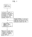
- FIG. 1 is a flowchart of steps in a method embodying the invention.
- a maximum value of diffusible hydrogen content of unfailed specimens H c
- Weibull stress is then calculated from samples in a simple shape. Relationships between H c and the Weibull stress are found, and a plotted curve of maximum values of diffusible hydrogen contents of unfailed specimens (H c ) and the Weibull stress ( ⁇ w ) is prepared.
- FIG. 4 is a typical example of this curve.
- the environmental hydrogen content of the steel member arising from the environment due to corrosion (H e ) is experimentally measured or predicted from empirical values.
- Weibull stress ( ⁇ w A) in H c which is equal to H e is calculated from the curve.
- the shape and working stress of a steel member in actual use are determined so as to provide Weibull stress ( ⁇ w B) which is less than the Weibull stress ( ⁇ w A).
- the shape and working stress of a steel member in actual use are stipulated to ensure that ⁇ ⁇ w A > ⁇ w B.
- ⁇ w A > ⁇ w B no delayed fracture is found in the steel member.
- ⁇ w A ⁇ ⁇ w B a delayed fracture is likely to be found in the steel member.
- the present invention determines a working environment of a steel member so as to provide the content of diffusible hydrogen entered into steel from the environment due to corrosion during the use of the steel member (H e ), which is smaller than the maximum value of diffusible hydrogen contents of unfailed specimens (H c ) in the Weibull stress ( ⁇ w B) calculated on the basis of the shape and working stress of the steel member in actual use.
- the working environment of the steel member in actual use is determined so as to provide H c > H e .
- the working environment indicates, for instance, temperature, humidity, components of atmospheric gas, salt content in the atmosphere and the like in a place where a steel member is used. Specifically, it means an environment where a steel member is used, such as the seaside, inside an engine room of a vehicle, inside a tunnel on a freeway, and the like.
- the present invention finds relationships between a maximum value of diffusible hydrogen contents of unfailed specimens (H c ) and Weibull stress ( ⁇ w A), and finds the content of diffusible hydrogen entered into steel from the environment due to corrosion during the use of the steel member (H e ). Subsequently, the Weibull stress ( ⁇ w A) is found in the H c which is equal to the H e , and the Weibull stress ( ⁇ w A) is compared to Weibull stress ( ⁇ w B) which is calculated from a shape and working stress of the steel member in use. It is determined that there will be no delayed fracture when ⁇ w A is larger than ⁇ w B. According to the present invention, the occurrence of a delayed fracture can be accurately predicted for a steel member.
- the present invention is applicable to any steel member as a component, without restriction as to the composition of the steel member.
- the present invention is preferably applied to high strength steel which has tensile strength of more than 1,000 MPa and has been rarely employed for practical use.
- Table 1 shows conditions of a delayed fracture test. Symbols in Table 1 will be explained.
- K t indicates a stress concentration factor, and is a constant which is determined by a notch shape of a sample. For instance, a sample having no notch has K t of 1.0.
- ⁇ w is calculated Weibull stress.
- ⁇ max is maximum applied stress.
- ⁇ ave is average applied stress.
- H c is a measured maximum value of diffusible hydrogen contents of unfailed specimens.
- a used steel member has tensile strength of about 1,400 MPa.
- the chemical components thereof are 0.40% of C, 0.24% of Si, 0.8% of Mn, 0.02% of P, 0.007% of S, 1.0% of Cr and 0.16% of Mo in mass%.
- the remainder consists of Fe and inevitable impurities.
- the sample is a round bar having a diameter of 10 mm, and has a ring notch at the center.
- H c was measured under each condition.
- Typical maximum applied stress ( ⁇ max ) for calculation is shown in FIG. 3.
- FIG. 3 Typical maximum applied stress ( ⁇ max ) for calculation is shown in FIG. 3.
- FIG. 3 shows the relationship between distances from a notch root of a sample and maximum principal stress ( ⁇ max ).
- the maximum applied stress ( ⁇ max ) changes in a tensile direction.
- the stress is at the maximum of 2,544 MPa near a notch root, and sharply decreases as one moves away from the notch root.
- the stress becomes constant at 587 MPa at a furthest distance from the notch root.
- the stress is not at the maximum level at the notch root because the material has a partial yield and plastic deformation in this example.
- FIG. 2 shows an area V f which is used for the calculation of the Weibull stress ( ⁇ w ).
- V f is an area which is likely to be fractured.
- FIG. 4 shows the relationship between calculation results of the Weibull stress ( ⁇ w ) and measurement results of maximum values of diffusible hydrogen contents of unfailed specimens (H c ). It is found from FIG. 4 that ⁇ w and H c have principal relations and are not influenced by K t . This knowledge is extremely useful in predicting the occurrence of a delayed fracture.
- the content of diffusible hydrogen entered into steel from the environment due to corrosion (H e ) of the steel member can be empirically predicted from the working environment. It is found that the H e of the steel member is 0.05 to 0.09 ppm. According to FIG. 4, ⁇ w is 2,300 MPa when H e is 0.09 ppm. Accordingly, it is possible to predict that the occurrence of a delayed fracture of the steel member is zero at less than 2,300 MPa of ⁇ w .
- FIG. 5 shows the relationship between calculation results of average applied stress ( ⁇ ave ) and measurement results of maximum values of diffusible hydrogen contents of unfailed specimens (H c ). It is found, from FIG. 5, that ⁇ ave and H c have no principal relations and are heavily influenced by K t . It is known that the steel member has 0.05 to 0.09 ppm of H e . However, it is almost impossible to predict, from FIG. 5, the level of the average applied stress ( ⁇ ave ) from which the steel member will have no delayed fracture. This is because ⁇ ave where H c is larger than H e becomes different when K t is different.
- the occurrence of a delayed fracture of the steel member is predicted to be zero when ⁇ w is less than 2,300 MPa.
- a test was carried out to confirm whether or not this prediction was correct.
- An exposure test was performed under the same stress conditions as for the delayed fracture test. For the test, predetermined load was applied to samples. Three-percent salt solution was sprayed on the samples twice, in the morning and in the evening, and the samples were examined for fracture after 100 hours. The occurrence of a delayed fracture is found by performing the exposure test to twenty samples under each condition, and is a value where the number of fractured samples is divided by 20.
- FIG. 6 shows the results of the exposure test.
- FIG. 6 shows the effects of ⁇ w on the occurrence of a delayed fracture.
- ⁇ w was less than 2,300 MPa
- the occurrence of a delayed fracture was zero.
- the occurrence of a delayed fracture went up as ⁇ w increased. Accordingly, it is realized that the prediction based on FIG. 4 was correct, that is the occurrence of a delayed fracture of the steel member is zero at less than 2,300 MPa of ⁇ w .
- a delayed fracture can be prevented if the steel member is designed at less than 2,300 MPa of ⁇ w .
- FIG. 7 shows the effects of ⁇ ave on the occurrence of a delayed fracture.
- FIG. 7 has been conventionally used for the prediction of a delayed fracture.
- K t stress concentration factor
- a critical ⁇ ave that provides zero occurrence of a delayed fracture becomes different. It is almost impossible to predict the level of ⁇ ave from which no delayed fracture is caused in the steel member. It is also difficult to predict the occurrence of a delayed fracture of a steel member having a different shape from that of the steel member to which the delayed fracture test was carried out. It is obvious that, in the conventional method, a delayed fracture test has to be carried out to every design shape of a steel member.
- the present invention can accurately predict whether or not a steel member will have a delayed fracture.
- the present invention can also effectively prevent a delayed fracture by appropriately setting the shape and working stress, and working environment of a steel member. Even a steel member having a complex shape can be designed with an appropriate safety factor for actual use.
Landscapes
- Chemical & Material Sciences (AREA)
- Engineering & Computer Science (AREA)
- Health & Medical Sciences (AREA)
- Life Sciences & Earth Sciences (AREA)
- Metallurgy (AREA)
- Materials Engineering (AREA)
- Organic Chemistry (AREA)
- Mechanical Engineering (AREA)
- Immunology (AREA)
- Pathology (AREA)
- Analytical Chemistry (AREA)
- Biochemistry (AREA)
- General Physics & Mathematics (AREA)
- Physics & Mathematics (AREA)
- General Health & Medical Sciences (AREA)
- Food Science & Technology (AREA)
- Medicinal Chemistry (AREA)
- Investigating Strength Of Materials By Application Of Mechanical Stress (AREA)
- Investigating And Analyzing Materials By Characteristic Methods (AREA)
- Sampling And Sample Adjustment (AREA)
Abstract
Description


| Conditions of Delayed Fracture Test | |||||||
| Sample diameter/ mm | Kt | Applied stress/ tensile strength of notched specimen | σw/MPa | σmax/MPa | σave/MPa | Hc/mass ppm | Occurrence of delayed fracture |
| 10 | 6.9 | 0.86 | 2930 | 3434 | 1849 | 0.0692 | 1.00 |
| 10 | 6.9 | 0.72 | 2715 | 3274 | 1543 | 0.0794 | 0.80 |
| 10 | 6.9 | 0.47 | 2334 | 2860 | 1004 | 0.0908 | 0.10 |
| 10 | 6.9 | 0.40 | 2196 | 2710 | 841 | 0.1408 | 0.00 |
| 10 | 6.9 | 0.33 | 2021 | 2494 | 701 | 0.3355 | 0.00 |
| 10 | 4.9 | 0.86 | 2828 | 3164 | 1849 | 0.0729 | 0.90 |
| 10 | 4.9 | 0.72 | 2606 | 2961 | 1543 | 0.0812 | 0.50 |
| 10 | 4.9 | 0.47 | 2203 | 2544 | 1004 | 0.1276 | 0.00 |
| 10 | 4.9 | 0.40 | 2047 | 2379 | 841 | 0.2151 | 0.00 |
| 10 | 4.9 | 0.33 | 1863 | 2187 | 701 | 0.5240 | 0.00 |
| 10 | 3.3 | 0.86 | 2732 | 2808 | 1849 | 0.0754 | 0.85 |
| 10 | 3.3 | 0.72 | 2478 | 2590 | 1543 | 0.0850 | 0.30 |
| 10 | 3.3 | 0.60 | 2194 | 2364 | 1291 | 0.1439 | 0.00 |
| 10 | 3.3 | 0.47 | 1921 | 2110 | 1004 | 0.3940 | 0.00 |
Claims (5)
- A method for setting a shape and working stress of a steel member comprising the steps of finding the relationship between a maximum value of diffusible hydrogen contents of unfailed specimens (Hc) and Weibull stress and finding a content of diffusible hydrogen entered into steel from the environment due to corrosion during use of the steel member (He); finding Weibull stress in the Hc which is equal to the He; and determining a shape and working stress of the steel member so as to provide stress below the Weibull stress.
- The method according to Claim 1, wherein the Weibull stress is calculated by an electronic arithmetic unit in accordance with a finite element method based on the following Formula 1:wherein σeff is maximum principal stress which influences a fracture; Vo is a reference volume of a certain area where a fracture is likely to occur; Vf is an area where a fracture is likely to occur; and m is a constant called Weibull shape parameter.

- A method for setting a working environment of a steel member comprising the steps of finding the relationship between a maximum value of diffusible hydrogen contents of unfailed specimens (Hc) and Weibull stress (σwA) and finding Weibull stress (σwB) of the steel member in actual use based on a shape and working stress of the steel member in actual use; finding Hc in the Weibull stress (σwA) which is equal to the Weibull stress (σwB) ; and determining a working environment of the steel member so as to provide a content of diffusible hydrogen entered into steel from the environment due to corrosion during use of the steel member (He) which is less than the Hc.
- The method according to Claim 3, wherein the Weibull stress is calculated by an electronic arithmetic unit in accordance with a finite element method based on the following Formula 1:wherein σeff is maximum principal stress which influences a fracture; Vo is a reference volume of a certain area where a fracture is likely to occur; Vf is an area where a fracture is likely to occur; and m is a constant called Weibull shape parameter.

- A method for evaluating a delayed fracture of a steel member comprising the steps of finding the relationship between a maximum value of diffusible hydrogen contents of unfailed specimens (Hc) and Weibull stress (σwA) and finding a content of diffusible hydrogen entered into steel from the environment due to corrosion during use of the steel member (He); finding the Weibull stress (σwA) in the Hc which is equal to the He; and comparing the σwA to Weibull stress (σwB) which is calculated from a shape and working stress of the steel member in use, and determining that there will be no delayed fracture when the σwA is larger than the σwB.
Applications Claiming Priority (2)
| Application Number | Priority Date | Filing Date | Title |
|---|---|---|---|
| JP2000264716 | 2000-08-31 | ||
| JP2000264716A JP4148639B2 (en) | 2000-08-31 | 2000-08-31 | How to use steel members and how to set them |
Publications (2)
| Publication Number | Publication Date |
|---|---|
| EP1184657A2 true EP1184657A2 (en) | 2002-03-06 |
| EP1184657A3 EP1184657A3 (en) | 2003-08-06 |
Family
ID=18752098
Family Applications (1)
| Application Number | Title | Priority Date | Filing Date |
|---|---|---|---|
| EP01307251A Withdrawn EP1184657A3 (en) | 2000-08-31 | 2001-08-28 | Method for evaluating a delayed fracture of a steel member |
Country Status (5)
| Country | Link |
|---|---|
| US (1) | US6523416B2 (en) |
| EP (1) | EP1184657A3 (en) |
| JP (1) | JP4148639B2 (en) |
| KR (1) | KR20020018136A (en) |
| CN (1) | CN1344932A (en) |
Cited By (3)
| Publication number | Priority date | Publication date | Assignee | Title |
|---|---|---|---|---|
| US7641742B2 (en) | 2004-01-15 | 2010-01-05 | Ntn Corporation | Rolling bearing and heat treatment method for steel |
| US7682087B2 (en) | 2003-02-28 | 2010-03-23 | Ntn Corporation | Transmission component, method of manufacturing the same, and tapered roller bearing |
| US8425690B2 (en) | 2001-11-29 | 2013-04-23 | Ntn Corporation | Bearing part, heat treatment method thereof, and rolling bearing |
Families Citing this family (82)
| Publication number | Priority date | Publication date | Assignee | Title |
|---|---|---|---|---|
| US6724220B1 (en) | 2000-10-26 | 2004-04-20 | Cyress Semiconductor Corporation | Programmable microcontroller architecture (mixed analog/digital) |
| US8103496B1 (en) | 2000-10-26 | 2012-01-24 | Cypress Semicondutor Corporation | Breakpoint control in an in-circuit emulation system |
| US8160864B1 (en) | 2000-10-26 | 2012-04-17 | Cypress Semiconductor Corporation | In-circuit emulator and pod synchronized boot |
| US8176296B2 (en) | 2000-10-26 | 2012-05-08 | Cypress Semiconductor Corporation | Programmable microcontroller architecture |
| US7765095B1 (en) | 2000-10-26 | 2010-07-27 | Cypress Semiconductor Corporation | Conditional branching in an in-circuit emulation system |
| US8149048B1 (en) | 2000-10-26 | 2012-04-03 | Cypress Semiconductor Corporation | Apparatus and method for programmable power management in a programmable analog circuit block |
| US7406674B1 (en) | 2001-10-24 | 2008-07-29 | Cypress Semiconductor Corporation | Method and apparatus for generating microcontroller configuration information |
| US8078970B1 (en) | 2001-11-09 | 2011-12-13 | Cypress Semiconductor Corporation | Graphical user interface with user-selectable list-box |
| US8042093B1 (en) | 2001-11-15 | 2011-10-18 | Cypress Semiconductor Corporation | System providing automatic source code generation for personalization and parameterization of user modules |
| US7844437B1 (en) | 2001-11-19 | 2010-11-30 | Cypress Semiconductor Corporation | System and method for performing next placements and pruning of disallowed placements for programming an integrated circuit |
| US6971004B1 (en) | 2001-11-19 | 2005-11-29 | Cypress Semiconductor Corp. | System and method of dynamically reconfiguring a programmable integrated circuit |
| US7774190B1 (en) | 2001-11-19 | 2010-08-10 | Cypress Semiconductor Corporation | Sleep and stall in an in-circuit emulation system |
| US8069405B1 (en) | 2001-11-19 | 2011-11-29 | Cypress Semiconductor Corporation | User interface for efficiently browsing an electronic document using data-driven tabs |
| US7770113B1 (en) | 2001-11-19 | 2010-08-03 | Cypress Semiconductor Corporation | System and method for dynamically generating a configuration datasheet |
| US8103497B1 (en) | 2002-03-28 | 2012-01-24 | Cypress Semiconductor Corporation | External interface for event architecture |
| US7308608B1 (en) | 2002-05-01 | 2007-12-11 | Cypress Semiconductor Corporation | Reconfigurable testing system and method |
| US7761845B1 (en) | 2002-09-09 | 2010-07-20 | Cypress Semiconductor Corporation | Method for parameterizing a user module |
| JP2004301321A (en) | 2003-03-14 | 2004-10-28 | Ntn Corp | Bearing for alternator and bearing for pulley |
| JP4152283B2 (en) * | 2003-08-29 | 2008-09-17 | Ntn株式会社 | Heat treatment method for bearing parts |
| US7594762B2 (en) | 2004-01-09 | 2009-09-29 | Ntn Corporation | Thrust needle roller bearing, support structure receiving thrust load of compressor for car air-conditioner, support structure receiving thrust load of automatic transmission, support structure for continuously variable transmission, and support structure receivin |
| US7295049B1 (en) | 2004-03-25 | 2007-11-13 | Cypress Semiconductor Corporation | Method and circuit for rapid alignment of signals |
| US7805177B2 (en) * | 2004-06-23 | 2010-09-28 | M2S, Inc. | Method for determining the risk of rupture of a blood vessel |
| US7899516B2 (en) * | 2004-06-23 | 2011-03-01 | M2S, Inc. | Method and apparatus for determining the risk of rupture of a blood vessel using the contiguous element defined area |
| US8069436B2 (en) | 2004-08-13 | 2011-11-29 | Cypress Semiconductor Corporation | Providing hardware independence to automate code generation of processing device firmware |
| US8286125B2 (en) | 2004-08-13 | 2012-10-09 | Cypress Semiconductor Corporation | Model for a hardware device-independent method of defining embedded firmware for programmable systems |
| US7332976B1 (en) | 2005-02-04 | 2008-02-19 | Cypress Semiconductor Corporation | Poly-phase frequency synthesis oscillator |
| US7400183B1 (en) | 2005-05-05 | 2008-07-15 | Cypress Semiconductor Corporation | Voltage controlled oscillator delay cell and method |
| US8089461B2 (en) | 2005-06-23 | 2012-01-03 | Cypress Semiconductor Corporation | Touch wake for electronic devices |
| JP2007046717A (en) * | 2005-08-10 | 2007-02-22 | Ntn Corp | Rolling-contact shaft with joint claw |
| US7307485B1 (en) | 2005-11-14 | 2007-12-11 | Cypress Semiconductor Corporation | Capacitance sensor using relaxation oscillators |
| US8085067B1 (en) | 2005-12-21 | 2011-12-27 | Cypress Semiconductor Corporation | Differential-to-single ended signal converter circuit and method |
| US7312616B2 (en) | 2006-01-20 | 2007-12-25 | Cypress Semiconductor Corporation | Successive approximate capacitance measurement circuit |
| US20070176903A1 (en) * | 2006-01-31 | 2007-08-02 | Dahlin Jeffrey J | Capacitive touch sensor button activation |
| US8067948B2 (en) | 2006-03-27 | 2011-11-29 | Cypress Semiconductor Corporation | Input/output multiplexer bus |
| US8144125B2 (en) | 2006-03-30 | 2012-03-27 | Cypress Semiconductor Corporation | Apparatus and method for reducing average scan rate to detect a conductive object on a sensing device |
| US8040142B1 (en) | 2006-03-31 | 2011-10-18 | Cypress Semiconductor Corporation | Touch detection techniques for capacitive touch sense systems |
| US7721609B2 (en) | 2006-03-31 | 2010-05-25 | Cypress Semiconductor Corporation | Method and apparatus for sensing the force with which a button is pressed |
| US8089472B2 (en) | 2006-05-26 | 2012-01-03 | Cypress Semiconductor Corporation | Bidirectional slider with delete function |
| US8537121B2 (en) * | 2006-05-26 | 2013-09-17 | Cypress Semiconductor Corporation | Multi-function slider in touchpad |
| US8040321B2 (en) | 2006-07-10 | 2011-10-18 | Cypress Semiconductor Corporation | Touch-sensor with shared capacitive sensors |
| US7253643B1 (en) | 2006-07-19 | 2007-08-07 | Cypress Semiconductor Corporation | Uninterrupted radial capacitive sense interface |
| US9507465B2 (en) * | 2006-07-25 | 2016-11-29 | Cypress Semiconductor Corporation | Technique for increasing the sensitivity of capacitive sensor arrays |
| US9766738B1 (en) | 2006-08-23 | 2017-09-19 | Cypress Semiconductor Corporation | Position and usage based prioritization for capacitance sense interface |
| US8547114B2 (en) * | 2006-11-14 | 2013-10-01 | Cypress Semiconductor Corporation | Capacitance to code converter with sigma-delta modulator |
| US8089288B1 (en) | 2006-11-16 | 2012-01-03 | Cypress Semiconductor Corporation | Charge accumulation capacitance sensor with linear transfer characteristic |
| US8058937B2 (en) | 2007-01-30 | 2011-11-15 | Cypress Semiconductor Corporation | Setting a discharge rate and a charge rate of a relaxation oscillator circuit |
| US7737724B2 (en) | 2007-04-17 | 2010-06-15 | Cypress Semiconductor Corporation | Universal digital block interconnection and channel routing |
| US8026739B2 (en) | 2007-04-17 | 2011-09-27 | Cypress Semiconductor Corporation | System level interconnect with programmable switching |
| US8516025B2 (en) | 2007-04-17 | 2013-08-20 | Cypress Semiconductor Corporation | Clock driven dynamic datapath chaining |
| US9564902B2 (en) | 2007-04-17 | 2017-02-07 | Cypress Semiconductor Corporation | Dynamically configurable and re-configurable data path |
| US8092083B2 (en) | 2007-04-17 | 2012-01-10 | Cypress Semiconductor Corporation | Temperature sensor with digital bandgap |
| US8040266B2 (en) | 2007-04-17 | 2011-10-18 | Cypress Semiconductor Corporation | Programmable sigma-delta analog-to-digital converter |
| US8130025B2 (en) | 2007-04-17 | 2012-03-06 | Cypress Semiconductor Corporation | Numerical band gap |
| US8266575B1 (en) | 2007-04-25 | 2012-09-11 | Cypress Semiconductor Corporation | Systems and methods for dynamically reconfiguring a programmable system on a chip |
| US9720805B1 (en) | 2007-04-25 | 2017-08-01 | Cypress Semiconductor Corporation | System and method for controlling a target device |
| US8065653B1 (en) | 2007-04-25 | 2011-11-22 | Cypress Semiconductor Corporation | Configuration of programmable IC design elements |
| US8144126B2 (en) | 2007-05-07 | 2012-03-27 | Cypress Semiconductor Corporation | Reducing sleep current in a capacitance sensing system |
| US9500686B1 (en) | 2007-06-29 | 2016-11-22 | Cypress Semiconductor Corporation | Capacitance measurement system and methods |
| US8570053B1 (en) | 2007-07-03 | 2013-10-29 | Cypress Semiconductor Corporation | Capacitive field sensor with sigma-delta modulator |
| WO2009006556A1 (en) | 2007-07-03 | 2009-01-08 | Cypress Semiconductor Corporation | Normalizing capacitive sensor array signals |
| US8089289B1 (en) | 2007-07-03 | 2012-01-03 | Cypress Semiconductor Corporation | Capacitive field sensor with sigma-delta modulator |
| US8169238B1 (en) | 2007-07-03 | 2012-05-01 | Cypress Semiconductor Corporation | Capacitance to frequency converter |
| US8049569B1 (en) | 2007-09-05 | 2011-11-01 | Cypress Semiconductor Corporation | Circuit and method for improving the accuracy of a crystal-less oscillator having dual-frequency modes |
| JP5038113B2 (en) * | 2007-12-05 | 2012-10-03 | 川崎重工業株式会社 | Destructive evaluation method for structures |
| JP5247160B2 (en) * | 2008-01-17 | 2013-07-24 | 株式会社アールデック | Hydrogen amount measuring device |
| US8525798B2 (en) | 2008-01-28 | 2013-09-03 | Cypress Semiconductor Corporation | Touch sensing |
| US8487912B1 (en) | 2008-02-01 | 2013-07-16 | Cypress Semiconductor Corporation | Capacitive sense touch device with hysteresis threshold |
| US8358142B2 (en) | 2008-02-27 | 2013-01-22 | Cypress Semiconductor Corporation | Methods and circuits for measuring mutual and self capacitance |
| US8319505B1 (en) | 2008-10-24 | 2012-11-27 | Cypress Semiconductor Corporation | Methods and circuits for measuring mutual and self capacitance |
| US9104273B1 (en) | 2008-02-29 | 2015-08-11 | Cypress Semiconductor Corporation | Multi-touch sensing method |
| US8321174B1 (en) | 2008-09-26 | 2012-11-27 | Cypress Semiconductor Corporation | System and method to measure capacitance of capacitive sensor array |
| US8487639B1 (en) | 2008-11-21 | 2013-07-16 | Cypress Semiconductor Corporation | Receive demodulator for capacitive sensing |
| US8866500B2 (en) | 2009-03-26 | 2014-10-21 | Cypress Semiconductor Corporation | Multi-functional capacitance sensing circuit with a current conveyor |
| JP2010256351A (en) * | 2009-04-01 | 2010-11-11 | Nippon Steel Corp | Fatigue failure probability estimation device for member, fatigue failure probability estimation method for member, and computer program |
| US9448964B2 (en) | 2009-05-04 | 2016-09-20 | Cypress Semiconductor Corporation | Autonomous control in a programmable system |
| US8723827B2 (en) | 2009-07-28 | 2014-05-13 | Cypress Semiconductor Corporation | Predictive touch surface scanning |
| US9268441B2 (en) | 2011-04-05 | 2016-02-23 | Parade Technologies, Ltd. | Active integrator for a capacitive sense array |
| JP6186658B2 (en) * | 2013-11-29 | 2017-08-30 | 三菱重工業株式会社 | Welded structure design method and welded structure manufacturing method |
| CN104198672B (en) * | 2014-09-01 | 2016-03-02 | 北京科技大学 | Based on the bridge cable corrosion monitoring method that plane stress state stress is concentrated |
| JP6973193B2 (en) * | 2017-03-22 | 2021-11-24 | 日本製鉄株式会社 | Hydrogen embrittlement resistance evaluation method |
| CN109753733B (en) * | 2019-01-08 | 2023-01-31 | 哈尔滨工业大学(深圳) | Method and system for determining closing temperature of space steel structure construction |
| EP4194583A4 (en) * | 2020-09-03 | 2024-06-05 | JFE Steel Corporation | METHOD FOR PREDICTING THE AMOUNT OF HYDROGEN ABSORBED IN A STEEL STRIP, METHOD FOR MANUFACTURING |
Family Cites Families (9)
| Publication number | Priority date | Publication date | Assignee | Title |
|---|---|---|---|---|
| US4475963A (en) * | 1981-02-05 | 1984-10-09 | Kabushiki Kaisha Kobe Seiko Sho | Method for postweld heat treatment |
| JPS58153140A (en) * | 1982-03-08 | 1983-09-12 | Masami Kobayashi | Breaking test apparatus for metal piece |
| US4552024A (en) * | 1984-04-10 | 1985-11-12 | Ford Motor Company | Device for directly analyzing strength of ceramic tool bits |
| CA1307880C (en) * | 1987-10-07 | 1992-09-29 | Bradley J. Miller | Thermally stable joints between materials with different thermal expansion coefficients |
| JPH08145862A (en) * | 1994-11-28 | 1996-06-07 | Nippon Steel Corp | Delayed fracture evaluation method for metallic materials |
| JPH08210958A (en) * | 1995-02-07 | 1996-08-20 | Mitsubishi Heavy Ind Ltd | Piping / pressure vessel breakage monitoring method |
| JPH08334445A (en) * | 1995-06-08 | 1996-12-17 | Mitsubishi Heavy Ind Ltd | WPS effect monitoring method for cracks |
| JP3020162B1 (en) * | 1998-12-17 | 2000-03-15 | 広島大学長 | Sacrificial specimen for long-term stress monitoring of structures and method of use |
| AU4658700A (en) * | 1999-04-23 | 2000-11-10 | Mai H. Doan-Trinh | Method of manufacturing a ceramic valve ball |
-
2000
- 2000-08-31 JP JP2000264716A patent/JP4148639B2/en not_active Expired - Fee Related
-
2001
- 2001-08-28 EP EP01307251A patent/EP1184657A3/en not_active Withdrawn
- 2001-08-29 US US09/940,669 patent/US6523416B2/en not_active Expired - Fee Related
- 2001-08-30 KR KR1020010052740A patent/KR20020018136A/en not_active Withdrawn
- 2001-08-31 CN CN01140712A patent/CN1344932A/en active Pending
Cited By (3)
| Publication number | Priority date | Publication date | Assignee | Title |
|---|---|---|---|---|
| US8425690B2 (en) | 2001-11-29 | 2013-04-23 | Ntn Corporation | Bearing part, heat treatment method thereof, and rolling bearing |
| US7682087B2 (en) | 2003-02-28 | 2010-03-23 | Ntn Corporation | Transmission component, method of manufacturing the same, and tapered roller bearing |
| US7641742B2 (en) | 2004-01-15 | 2010-01-05 | Ntn Corporation | Rolling bearing and heat treatment method for steel |
Also Published As
| Publication number | Publication date |
|---|---|
| KR20020018136A (en) | 2002-03-07 |
| EP1184657A3 (en) | 2003-08-06 |
| CN1344932A (en) | 2002-04-17 |
| JP2002071674A (en) | 2002-03-12 |
| JP4148639B2 (en) | 2008-09-10 |
| US20020043111A1 (en) | 2002-04-18 |
| US6523416B2 (en) | 2003-02-25 |
Similar Documents
| Publication | Publication Date | Title |
|---|---|---|
| US6523416B2 (en) | Method for setting shape and working stress, and working environment of steel member | |
| CN108398320B (en) | Method for measuring tensile stress corrosion of wrought aluminum alloy | |
| KR20080002410A (en) | Method of obtaining true strain-stress curve for high strain using tensile test and finite element method and tensile tester using the same | |
| EP2223089A1 (en) | Method of determining fatigue life and remaining life | |
| EP0517238B1 (en) | Method of and apparatus for estimating remaining service life of material being exposed to irradiation | |
| KR20150057553A (en) | Method for predicting fatigue life | |
| JP2001264240A (en) | Method for evaluating hydrogen embrittlement susceptibility of steel and steel excellent in hydrogen embrittlement resistance | |
| JP2018159701A (en) | Hydrogen embrittlement resistance evaluation method | |
| CN110489848A (en) | A kind of difference seawater velocity Corrosion Fatigue Crack Propagation rate prediction method | |
| CN113449432A (en) | Fatigue life prediction method based on unloading elastic strain energy density | |
| KR20260046510A (en) | Method, apparatus, and program for predicting delayed fracture of press-formed products, and method for manufacturing press-formed products | |
| Wan et al. | Interactions between mechanical and environmental variables for short fatigue cracks in a 2024-T3 aluminum alloy in 0.5 M NaCl solutions | |
| CN118734552A (en) | A method for identifying permanent stress in structures based on monitoring strain inversion | |
| Roebuck et al. | Data acquisition and analysis of tensile properties for metal matrix composites | |
| JP3281147B2 (en) | Method for predicting deterioration of metal materials and remaining life | |
| JPH09273992A (en) | Quantitative analysis method of oxide layer on metal surface | |
| JP2023145212A (en) | Method of evaluating delayed fracture properties | |
| RU2215280C1 (en) | Procedure evaluating residual service life of parts | |
| KR100660209B1 (en) | Recrystallization Method for Hot Rolling Process Analysis | |
| Babuska et al. | Quantitative assessment of the accuracy of constitutive laws for plasticity with an emphasis on cyclic deformation | |
| CN86103893A (en) | The method of fast measuring contact fatigue strength limit of material | |
| US20250190644A1 (en) | Method, device, and program for predicting delayed fracture in press formed part, and method of manufacturing press formed part | |
| CN121185732B (en) | Quality inspection methods and systems for battery pack housing production | |
| US11921065B2 (en) | X-ray fluorescence spectrometer | |
| JPH0968516A (en) | Glow discharge mass spectrometry |
Legal Events
| Date | Code | Title | Description |
|---|---|---|---|
| PUAI | Public reference made under article 153(3) epc to a published international application that has entered the european phase |
Free format text: ORIGINAL CODE: 0009012 |
|
| AK | Designated contracting states |
Kind code of ref document: A2 Designated state(s): AT BE CH CY DE DK ES FI FR GB GR IE IT LI LU MC NL PT SE TR |
|
| AX | Request for extension of the european patent |
Free format text: AL;LT;LV;MK;RO;SI |
|
| PUAL | Search report despatched |
Free format text: ORIGINAL CODE: 0009013 |
|
| AK | Designated contracting states |
Designated state(s): AT BE CH CY DE DK ES FI FR GB GR IE IT LI LU MC NL PT SE TR |
|
| AX | Request for extension of the european patent |
Extension state: AL LT LV MK RO SI |
|
| 17P | Request for examination filed |
Effective date: 20030922 |
|
| RAP1 | Party data changed (applicant data changed or rights of an application transferred) |
Owner name: NATIONAL INSTITUTE FOR MATERIALS SCIENCE Owner name: JFE STEEL CORPORATION |
|
| AKX | Designation fees paid |
Designated state(s): DE FR GB IT |
|
| STAA | Information on the status of an ep patent application or granted ep patent |
Free format text: STATUS: THE APPLICATION IS DEEMED TO BE WITHDRAWN |
|
| 18D | Application deemed to be withdrawn |
Effective date: 20070301 |