EP1184243A1 - Built-in hydraulic jack for a car - Google Patents
Built-in hydraulic jack for a car Download PDFInfo
- Publication number
- EP1184243A1 EP1184243A1 EP01600016A EP01600016A EP1184243A1 EP 1184243 A1 EP1184243 A1 EP 1184243A1 EP 01600016 A EP01600016 A EP 01600016A EP 01600016 A EP01600016 A EP 01600016A EP 1184243 A1 EP1184243 A1 EP 1184243A1
- Authority
- EP
- European Patent Office
- Prior art keywords
- automobile
- oil
- valves
- hydrostatic
- cycles
- Prior art date
- Legal status (The legal status is an assumption and is not a legal conclusion. Google has not performed a legal analysis and makes no representation as to the accuracy of the status listed.)
- Withdrawn
Links
Images
Classifications
-
- B—PERFORMING OPERATIONS; TRANSPORTING
- B60—VEHICLES IN GENERAL
- B60S—SERVICING, CLEANING, REPAIRING, SUPPORTING, LIFTING, OR MANOEUVRING OF VEHICLES, NOT OTHERWISE PROVIDED FOR
- B60S9/00—Ground-engaging vehicle fittings for supporting, lifting, or manoeuvring the vehicle, wholly or in part, e.g. built-in jacks
- B60S9/02—Ground-engaging vehicle fittings for supporting, lifting, or manoeuvring the vehicle, wholly or in part, e.g. built-in jacks for only lifting or supporting
- B60S9/10—Ground-engaging vehicle fittings for supporting, lifting, or manoeuvring the vehicle, wholly or in part, e.g. built-in jacks for only lifting or supporting by fluid pressure
- B60S9/12—Ground-engaging vehicle fittings for supporting, lifting, or manoeuvring the vehicle, wholly or in part, e.g. built-in jacks for only lifting or supporting by fluid pressure of telescopic type
-
- F—MECHANICAL ENGINEERING; LIGHTING; HEATING; WEAPONS; BLASTING
- F15—FLUID-PRESSURE ACTUATORS; HYDRAULICS OR PNEUMATICS IN GENERAL
- F15B—SYSTEMS ACTING BY MEANS OF FLUIDS IN GENERAL; FLUID-PRESSURE ACTUATORS, e.g. SERVOMOTORS; DETAILS OF FLUID-PRESSURE SYSTEMS, NOT OTHERWISE PROVIDED FOR
- F15B11/00—Servomotor systems without provision for follow-up action; Circuits therefor
- F15B11/003—Systems with load-holding valves
-
- F—MECHANICAL ENGINEERING; LIGHTING; HEATING; WEAPONS; BLASTING
- F15—FLUID-PRESSURE ACTUATORS; HYDRAULICS OR PNEUMATICS IN GENERAL
- F15B—SYSTEMS ACTING BY MEANS OF FLUIDS IN GENERAL; FLUID-PRESSURE ACTUATORS, e.g. SERVOMOTORS; DETAILS OF FLUID-PRESSURE SYSTEMS, NOT OTHERWISE PROVIDED FOR
- F15B11/00—Servomotor systems without provision for follow-up action; Circuits therefor
- F15B11/02—Systems essentially incorporating special features for controlling the speed or actuating force of an output member
- F15B11/04—Systems essentially incorporating special features for controlling the speed or actuating force of an output member for controlling the speed
- F15B11/0413—Systems essentially incorporating special features for controlling the speed or actuating force of an output member for controlling the speed in one direction only, with no control in the reverse direction, e.g. check valve in parallel with a throttle valve
-
- F—MECHANICAL ENGINEERING; LIGHTING; HEATING; WEAPONS; BLASTING
- F15—FLUID-PRESSURE ACTUATORS; HYDRAULICS OR PNEUMATICS IN GENERAL
- F15B—SYSTEMS ACTING BY MEANS OF FLUIDS IN GENERAL; FLUID-PRESSURE ACTUATORS, e.g. SERVOMOTORS; DETAILS OF FLUID-PRESSURE SYSTEMS, NOT OTHERWISE PROVIDED FOR
- F15B11/00—Servomotor systems without provision for follow-up action; Circuits therefor
- F15B11/16—Servomotor systems without provision for follow-up action; Circuits therefor with two or more servomotors
-
- F—MECHANICAL ENGINEERING; LIGHTING; HEATING; WEAPONS; BLASTING
- F15—FLUID-PRESSURE ACTUATORS; HYDRAULICS OR PNEUMATICS IN GENERAL
- F15B—SYSTEMS ACTING BY MEANS OF FLUIDS IN GENERAL; FLUID-PRESSURE ACTUATORS, e.g. SERVOMOTORS; DETAILS OF FLUID-PRESSURE SYSTEMS, NOT OTHERWISE PROVIDED FOR
- F15B2211/00—Circuits for servomotor systems
- F15B2211/20—Fluid pressure source, e.g. accumulator or variable axial piston pump
- F15B2211/205—Systems with pumps
- F15B2211/20507—Type of prime mover
- F15B2211/20515—Electric motor
-
- F—MECHANICAL ENGINEERING; LIGHTING; HEATING; WEAPONS; BLASTING
- F15—FLUID-PRESSURE ACTUATORS; HYDRAULICS OR PNEUMATICS IN GENERAL
- F15B—SYSTEMS ACTING BY MEANS OF FLUIDS IN GENERAL; FLUID-PRESSURE ACTUATORS, e.g. SERVOMOTORS; DETAILS OF FLUID-PRESSURE SYSTEMS, NOT OTHERWISE PROVIDED FOR
- F15B2211/00—Circuits for servomotor systems
- F15B2211/20—Fluid pressure source, e.g. accumulator or variable axial piston pump
- F15B2211/205—Systems with pumps
- F15B2211/2053—Type of pump
- F15B2211/20538—Type of pump constant capacity
-
- F—MECHANICAL ENGINEERING; LIGHTING; HEATING; WEAPONS; BLASTING
- F15—FLUID-PRESSURE ACTUATORS; HYDRAULICS OR PNEUMATICS IN GENERAL
- F15B—SYSTEMS ACTING BY MEANS OF FLUIDS IN GENERAL; FLUID-PRESSURE ACTUATORS, e.g. SERVOMOTORS; DETAILS OF FLUID-PRESSURE SYSTEMS, NOT OTHERWISE PROVIDED FOR
- F15B2211/00—Circuits for servomotor systems
- F15B2211/30—Directional control
- F15B2211/305—Directional control characterised by the type of valves
- F15B2211/30505—Non-return valves, i.e. check valves
- F15B2211/3051—Cross-check valves
-
- F—MECHANICAL ENGINEERING; LIGHTING; HEATING; WEAPONS; BLASTING
- F15—FLUID-PRESSURE ACTUATORS; HYDRAULICS OR PNEUMATICS IN GENERAL
- F15B—SYSTEMS ACTING BY MEANS OF FLUIDS IN GENERAL; FLUID-PRESSURE ACTUATORS, e.g. SERVOMOTORS; DETAILS OF FLUID-PRESSURE SYSTEMS, NOT OTHERWISE PROVIDED FOR
- F15B2211/00—Circuits for servomotor systems
- F15B2211/30—Directional control
- F15B2211/305—Directional control characterised by the type of valves
- F15B2211/30525—Directional control valves, e.g. 4/3-directional control valve
-
- F—MECHANICAL ENGINEERING; LIGHTING; HEATING; WEAPONS; BLASTING
- F15—FLUID-PRESSURE ACTUATORS; HYDRAULICS OR PNEUMATICS IN GENERAL
- F15B—SYSTEMS ACTING BY MEANS OF FLUIDS IN GENERAL; FLUID-PRESSURE ACTUATORS, e.g. SERVOMOTORS; DETAILS OF FLUID-PRESSURE SYSTEMS, NOT OTHERWISE PROVIDED FOR
- F15B2211/00—Circuits for servomotor systems
- F15B2211/30—Directional control
- F15B2211/31—Directional control characterised by the positions of the valve element
- F15B2211/3105—Neutral or centre positions
- F15B2211/3116—Neutral or centre positions the pump port being open in the centre position, e.g. so-called open centre
-
- F—MECHANICAL ENGINEERING; LIGHTING; HEATING; WEAPONS; BLASTING
- F15—FLUID-PRESSURE ACTUATORS; HYDRAULICS OR PNEUMATICS IN GENERAL
- F15B—SYSTEMS ACTING BY MEANS OF FLUIDS IN GENERAL; FLUID-PRESSURE ACTUATORS, e.g. SERVOMOTORS; DETAILS OF FLUID-PRESSURE SYSTEMS, NOT OTHERWISE PROVIDED FOR
- F15B2211/00—Circuits for servomotor systems
- F15B2211/30—Directional control
- F15B2211/315—Directional control characterised by the connections of the valve or valves in the circuit
- F15B2211/3157—Directional control characterised by the connections of the valve or valves in the circuit being connected to a pressure source, an output member and a return line
- F15B2211/31576—Directional control characterised by the connections of the valve or valves in the circuit being connected to a pressure source, an output member and a return line having a single pressure source and a single output member
-
- F—MECHANICAL ENGINEERING; LIGHTING; HEATING; WEAPONS; BLASTING
- F15—FLUID-PRESSURE ACTUATORS; HYDRAULICS OR PNEUMATICS IN GENERAL
- F15B—SYSTEMS ACTING BY MEANS OF FLUIDS IN GENERAL; FLUID-PRESSURE ACTUATORS, e.g. SERVOMOTORS; DETAILS OF FLUID-PRESSURE SYSTEMS, NOT OTHERWISE PROVIDED FOR
- F15B2211/00—Circuits for servomotor systems
- F15B2211/30—Directional control
- F15B2211/32—Directional control characterised by the type of actuation
- F15B2211/321—Directional control characterised by the type of actuation mechanically
- F15B2211/324—Directional control characterised by the type of actuation mechanically manually, e.g. by using a lever or pedal
-
- F—MECHANICAL ENGINEERING; LIGHTING; HEATING; WEAPONS; BLASTING
- F15—FLUID-PRESSURE ACTUATORS; HYDRAULICS OR PNEUMATICS IN GENERAL
- F15B—SYSTEMS ACTING BY MEANS OF FLUIDS IN GENERAL; FLUID-PRESSURE ACTUATORS, e.g. SERVOMOTORS; DETAILS OF FLUID-PRESSURE SYSTEMS, NOT OTHERWISE PROVIDED FOR
- F15B2211/00—Circuits for servomotor systems
- F15B2211/40—Flow control
- F15B2211/405—Flow control characterised by the type of flow control means or valve
- F15B2211/40515—Flow control characterised by the type of flow control means or valve with variable throttles or orifices
-
- F—MECHANICAL ENGINEERING; LIGHTING; HEATING; WEAPONS; BLASTING
- F15—FLUID-PRESSURE ACTUATORS; HYDRAULICS OR PNEUMATICS IN GENERAL
- F15B—SYSTEMS ACTING BY MEANS OF FLUIDS IN GENERAL; FLUID-PRESSURE ACTUATORS, e.g. SERVOMOTORS; DETAILS OF FLUID-PRESSURE SYSTEMS, NOT OTHERWISE PROVIDED FOR
- F15B2211/00—Circuits for servomotor systems
- F15B2211/40—Flow control
- F15B2211/41—Flow control characterised by the positions of the valve element
- F15B2211/413—Flow control characterised by the positions of the valve element the positions being continuously variable, e.g. as realised by proportional valves
-
- F—MECHANICAL ENGINEERING; LIGHTING; HEATING; WEAPONS; BLASTING
- F15—FLUID-PRESSURE ACTUATORS; HYDRAULICS OR PNEUMATICS IN GENERAL
- F15B—SYSTEMS ACTING BY MEANS OF FLUIDS IN GENERAL; FLUID-PRESSURE ACTUATORS, e.g. SERVOMOTORS; DETAILS OF FLUID-PRESSURE SYSTEMS, NOT OTHERWISE PROVIDED FOR
- F15B2211/00—Circuits for servomotor systems
- F15B2211/40—Flow control
- F15B2211/415—Flow control characterised by the connections of the flow control means in the circuit
- F15B2211/41527—Flow control characterised by the connections of the flow control means in the circuit being connected to an output member and a directional control valve
-
- F—MECHANICAL ENGINEERING; LIGHTING; HEATING; WEAPONS; BLASTING
- F15—FLUID-PRESSURE ACTUATORS; HYDRAULICS OR PNEUMATICS IN GENERAL
- F15B—SYSTEMS ACTING BY MEANS OF FLUIDS IN GENERAL; FLUID-PRESSURE ACTUATORS, e.g. SERVOMOTORS; DETAILS OF FLUID-PRESSURE SYSTEMS, NOT OTHERWISE PROVIDED FOR
- F15B2211/00—Circuits for servomotor systems
- F15B2211/40—Flow control
- F15B2211/42—Flow control characterised by the type of actuation
- F15B2211/428—Flow control characterised by the type of actuation actuated by fluid pressure
-
- F—MECHANICAL ENGINEERING; LIGHTING; HEATING; WEAPONS; BLASTING
- F15—FLUID-PRESSURE ACTUATORS; HYDRAULICS OR PNEUMATICS IN GENERAL
- F15B—SYSTEMS ACTING BY MEANS OF FLUIDS IN GENERAL; FLUID-PRESSURE ACTUATORS, e.g. SERVOMOTORS; DETAILS OF FLUID-PRESSURE SYSTEMS, NOT OTHERWISE PROVIDED FOR
- F15B2211/00—Circuits for servomotor systems
- F15B2211/50—Pressure control
- F15B2211/55—Pressure control for limiting a pressure up to a maximum pressure, e.g. by using a pressure relief valve
Definitions
- This invention refers to a hydraulic lift system situated properly on an automobile and composed of two hydraulic cycles independent from each other, which both end in two hydraulic cylinders double energy which are situated on both the left and right side of the automobile. With the help of these two cylinders we have the ability to elevate an automobile.
- This invention has the intention of improving the disadvantages above.
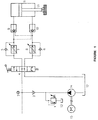
- Figure 1 shows one of the two identical hydraulic cycles, which compose the hydraulic lift system.
- the oil is absorbed from the oil lank(12) though simple direction of flow and stable special line(14) which starts up with an electric motor (15). After it passes the return valve (2) which protects the pump by not allowing the oil to return back, it divides into two hydrostatic cycles.
- the valve direction flow 4/3 (4 connections /3 positions) (4) and according to the position we manually set the oil:
- the two hydrostatic cycles are protected from possible undesired increase of oil pressure , with the adjustable valve minimal pressure (relief valve) (1) which checks the oil pressure in the conductor immediately after the pump opens when pressure is more than the preset pressure setting leads the oil to the oil tank (12).
- the adjustable valve minimal pressure (relief valve) (1) which checks the oil pressure in the conductor immediately after the pump opens when pressure is more than the preset pressure setting leads the oil to the oil tank (12).
- the oil measuring devise (manometer) (3) gives us the ability to oversee the pressure in the lift system.
Abstract
Description
- This invention refers to a hydraulic lift system situated properly on an automobile and composed of two hydraulic cycles independent from each other, which both end in two hydraulic cylinders double energy which are situated on both the left and right side of the automobile. With the help of these two cylinders we have the ability to elevate an automobile.
- The feeding of the system with oil is achieved by the use of a pump with simple direction flow and a stable special line, which starts with an electric motor.
In order to elevate an automobile in situations such as to change a tire or rise out of sand or mud etc. is now achieved by using a hand held jack , which all automobiles have. In order to correctly and safely use a jack to elevate an automobile we must first: a) have knowledge of how to use it b)have skill and experience in order to place it correctly especially when used on ground with a slope c) substantial muscle strength while working d) enough time which sometimes is precious. Finally we must take into consideration the possible soiling of hands and clothes from the parts of the jack which are covered with grease. - For all these reasons the use of a classic jack. today results in an unpleasant problem for many people which seek easy and simple solutions having safety in mind.
- This invention has the intention of improving the disadvantages above. One needs to do nothing more than adjust properly the direction of the oil flow to the hydrostatic cycle using the band lever of the 4 valve (figure 1) without much effort and avoiding contact with any other part of the system, we aachieve with safety the elevation of the automobile even if the ground has a slope. And all this is achieved in a short period of time.
- Figure 1 shows one of the two identical hydraulic cycles, which compose the hydraulic lift system. The oil is absorbed from the oil lank(12) though simple direction of flow and stable special line(14) which starts up with an electric motor (15). After it passes the return valve (2) which protects the pump by not allowing the oil to return back, it divides into two hydrostatic cycles. When reaching the valve direction flow 4/3 (4 connections /3 positions)
(4) and according to the position we manually set the oil: - a)returns to the oil tank if the valve(4) is positioned in the middle without starting up the remaining system of the cycle,
- b)is directed to the regulated choke valve (7) if valve (4) is in the upper position and after it passes to the return valve with the possibility of opposite flow (9) it reaches the upper part at the hydrostatic cylinder (11) and forces the piston (13) to rise coming out of the cylinder and thus elevating the automobile,
- c)is directed to the choke valve (8) if the valve (4) is in the lower position and after it passes the return valve with possible opposite flow (10) it reaches the lower part of the hydrostatic cylinder (11) and forces the piston (13) to rise going into the cylinder and thus lowering the automobile which was elevated earlier.
-
- In the second case b) the of which is compressed in the lower part of the cylinder through valve (10) which allows the opposite flow through the valve (6) and through valve (4) (upper position) returns to the oil tank.
- In the third case c) the oil which is compressed in the upper part of the cylinder through valve (9) which allows the opposite flow through ,passes the return valve (5) and trough valve (4) lower position returns to the oil tank.
- The two hydrostatic cycles are protected from possible undesired increase of oil pressure , with the adjustable valve minimal pressure (relief valve) (1) which checks the oil pressure in the conductor immediately after the pump opens when pressure is more than the preset pressure setting leads the oil to the oil tank (12).
- At the point where the oil divides into two cycles the oil measuring devise (manometer) (3) gives us the ability to oversee the pressure in the lift system.
Claims (2)
- The hydraulic automobile lift is composed of two identical hydrostatic cycles. Which are supplied with oil from the oil tank (12) through a simple direction pump a stable special line (14) which starts with an electric motor (15).
Each hydrostatic cycle is composed of a direction valve 4/3 (4 connections/3 positions) (4) which the oil is led according to the situation, to the regulated choke valves (7)(8) and from there through the return valves with possible opposite flow (9) (10) ends in the double energy hydrostatic cylinder (1) which moves piston (13) out or in to accomplish the elevation or lowering of the automobile. The oil is compressed in cylinder (11) with the movement of piston (13) returns to the oil tank (12) through valves (9) (10) and (5) or (6) accordingly after passing valve (4).
The hydraulic lift system is characteristic in that the two hydrostatic cycles which it is composed of are independent between them, and can work simultaneously or individually according to circumstance. There are also safety features for the protection of pump (14) relief valves (1) and return valves (2) as well as the safe function of the circuits and valves (5)(6)(7)(8)(9)(10). - The hydraulic automobile lift according to capability 1. is characteristic that the position of the hydrostatic cylinder is standard on the left and right side of the car nd that the piston ends (13) have the ability to slightly revolve at the point of support so that they can safely stabilize the automobile even on grounds with a slope.
Applications Claiming Priority (2)
| Application Number | Priority Date | Filing Date | Title |
|---|---|---|---|
| GR2000100295 | 2000-09-01 | ||
| GR20000100295A GR1003759B (en) | 2000-09-01 | 2000-09-01 | HYDRAULIC CAR LIFT. |
Publications (1)
| Publication Number | Publication Date |
|---|---|
| EP1184243A1 true EP1184243A1 (en) | 2002-03-06 |
Family
ID=10944367
Family Applications (1)
| Application Number | Title | Priority Date | Filing Date |
|---|---|---|---|
| EP01600016A Withdrawn EP1184243A1 (en) | 2000-09-01 | 2001-06-07 | Built-in hydraulic jack for a car |
Country Status (2)
| Country | Link |
|---|---|
| EP (1) | EP1184243A1 (en) |
| GR (1) | GR1003759B (en) |
Cited By (10)
| Publication number | Priority date | Publication date | Assignee | Title |
|---|---|---|---|---|
| FR2865246A1 (en) * | 2004-01-15 | 2005-07-22 | Gouache Ind Soc | Hydraulic energy storing device, has hydraulic distributor connected with hydraulic accumulator and elastomer pipe modules to distribute energy to actuators, and electronic system to send signal to allow/cut distribution to actuators |
| WO2013060232A1 (en) * | 2011-10-24 | 2013-05-02 | 中联重科股份有限公司 | Leg device for engineering machinery and concrete pump truck |
| CN103174690A (en) * | 2013-03-20 | 2013-06-26 | 大连奥托股份有限公司 | Air actuated control system used for translation mechanism |
| CN103321981A (en) * | 2013-07-01 | 2013-09-25 | 武汉船用机械有限责任公司 | Pressure protection system for oil cylinder of shark pincers |
| CN103591064A (en) * | 2013-11-18 | 2014-02-19 | 长沙中联消防机械有限公司 | Landing leg control hydraulic system and engineering vehicle |
| CN103625441A (en) * | 2013-12-13 | 2014-03-12 | 中联重科股份有限公司 | Control system and control method of landing legs |
| CN103727290A (en) * | 2013-07-16 | 2014-04-16 | 郭俊杰 | Energy-saving electric-hydraulic control device of large-torque high-temperature high-pressure valve |
| CN104329305A (en) * | 2014-10-17 | 2015-02-04 | 国家电网公司 | Hydraulic device of transformer substation cable drum carriage |
| CN105508321A (en) * | 2016-01-29 | 2016-04-20 | 中矿金业股份有限公司 | Unloading station distribution trolley hydraulic drive device and method |
| US11059324B2 (en) | 2015-09-18 | 2021-07-13 | Paul Rivera | Electrically actuated apparatus and method for tire replacement |
Citations (3)
| Publication number | Priority date | Publication date | Assignee | Title |
|---|---|---|---|---|
| US2472294A (en) * | 1947-03-07 | 1949-06-07 | Monroe D Hall | Hydraulic system for vehicle jacks |
| US2630787A (en) * | 1947-10-06 | 1953-03-10 | Sr Raymond Verch | Hydraulic jacking system |
| US2837312A (en) * | 1954-10-04 | 1958-06-03 | J H Holan Corp | Automatic jack |
-
2000
- 2000-09-01 GR GR20000100295A patent/GR1003759B/en unknown
-
2001
- 2001-06-07 EP EP01600016A patent/EP1184243A1/en not_active Withdrawn
Patent Citations (3)
| Publication number | Priority date | Publication date | Assignee | Title |
|---|---|---|---|---|
| US2472294A (en) * | 1947-03-07 | 1949-06-07 | Monroe D Hall | Hydraulic system for vehicle jacks |
| US2630787A (en) * | 1947-10-06 | 1953-03-10 | Sr Raymond Verch | Hydraulic jacking system |
| US2837312A (en) * | 1954-10-04 | 1958-06-03 | J H Holan Corp | Automatic jack |
Cited By (15)
| Publication number | Priority date | Publication date | Assignee | Title |
|---|---|---|---|---|
| FR2865246A1 (en) * | 2004-01-15 | 2005-07-22 | Gouache Ind Soc | Hydraulic energy storing device, has hydraulic distributor connected with hydraulic accumulator and elastomer pipe modules to distribute energy to actuators, and electronic system to send signal to allow/cut distribution to actuators |
| WO2013060232A1 (en) * | 2011-10-24 | 2013-05-02 | 中联重科股份有限公司 | Leg device for engineering machinery and concrete pump truck |
| CN103174690A (en) * | 2013-03-20 | 2013-06-26 | 大连奥托股份有限公司 | Air actuated control system used for translation mechanism |
| CN103321981A (en) * | 2013-07-01 | 2013-09-25 | 武汉船用机械有限责任公司 | Pressure protection system for oil cylinder of shark pincers |
| CN103321981B (en) * | 2013-07-01 | 2015-09-02 | 武汉船用机械有限责任公司 | Shark jaw oil cylinder working-pressure protective system |
| CN103727290A (en) * | 2013-07-16 | 2014-04-16 | 郭俊杰 | Energy-saving electric-hydraulic control device of large-torque high-temperature high-pressure valve |
| CN103727290B (en) * | 2013-07-16 | 2015-12-30 | 郭俊杰 | High pulling torque high-temperature high pressure valve energy-saving electric-hydraulic control gear |
| CN103591064A (en) * | 2013-11-18 | 2014-02-19 | 长沙中联消防机械有限公司 | Landing leg control hydraulic system and engineering vehicle |
| CN103591064B (en) * | 2013-11-18 | 2016-04-06 | 长沙中联消防机械有限公司 | Supporting leg hydraulic control system and engineering vehicle |
| CN103625441A (en) * | 2013-12-13 | 2014-03-12 | 中联重科股份有限公司 | Control system and control method of landing legs |
| CN103625441B (en) * | 2013-12-13 | 2016-09-21 | 中联重科股份有限公司 | The control system of supporting leg and control method |
| CN104329305A (en) * | 2014-10-17 | 2015-02-04 | 国家电网公司 | Hydraulic device of transformer substation cable drum carriage |
| CN104329305B (en) * | 2014-10-17 | 2017-02-15 | 山东大学 | Hydraulic device of transformer substation cable drum carriage |
| US11059324B2 (en) | 2015-09-18 | 2021-07-13 | Paul Rivera | Electrically actuated apparatus and method for tire replacement |
| CN105508321A (en) * | 2016-01-29 | 2016-04-20 | 中矿金业股份有限公司 | Unloading station distribution trolley hydraulic drive device and method |
Also Published As
| Publication number | Publication date |
|---|---|
| GR1003759B (en) | 2002-01-18 |
Similar Documents
| Publication | Publication Date | Title |
|---|---|---|
| EP1184243A1 (en) | Built-in hydraulic jack for a car | |
| US3952516A (en) | Hydraulic pressure amplifier | |
| EP2240361B1 (en) | Segmented platform | |
| EP1900676A3 (en) | Hoisting platform for hoisting loads | |
| DE10239140A1 (en) | Motorcycle with adjustable rear wheel swinging arm for standing on folding stand has adjustable length spring leg with coil spring between spring bases, hydraulic adjustment device for spring base(s) | |
| DE2242109C3 (en) | Lorry with a tiltable driver's cab and operating device | |
| CN104121242B (en) | Telescopic control system and engineering machinery | |
| CN108640014A (en) | A kind of clamping lifting gear for parking robot platform | |
| EP0163544A2 (en) | Caravan or trailer stabilizing & levelling system | |
| US20170298963A1 (en) | Integral Hydraulic System | |
| US4473213A (en) | Service jack including rack and pinion driven pump piston | |
| US4509723A (en) | Portable hydraulic lifting jack | |
| DE20112716U1 (en) | Manually operated no-load high-speed hoist | |
| US4359205A (en) | Hydraulically operated lifting apparatus and pump therefor | |
| GB2066188A (en) | Trailer jacking system | |
| US3166298A (en) | Fluid operated motor vehicle lifting jack | |
| DE687552C (en) | Truck trailer tipping device operated by liquid pressure for power and manual operation | |
| GB2237329A (en) | Jacking apparatus | |
| EP3231765A1 (en) | Integral hydraulic system | |
| US3243060A (en) | Vertical gate lift apparatus | |
| AT407514B (en) | Emergency brake for motor vehicles | |
| US3431727A (en) | Jack arrangement for trailers | |
| US3940338A (en) | Lifting vehicle having a control member adjustable into three different positions | |
| EP0155592B1 (en) | Fluid pump | |
| CN110127539A (en) | Lifting platform is used in a kind of assembly of automobile rear protective plate |
Legal Events
| Date | Code | Title | Description |
|---|---|---|---|
| PUAI | Public reference made under article 153(3) epc to a published international application that has entered the european phase |
Free format text: ORIGINAL CODE: 0009012 |
|
| AK | Designated contracting states |
Kind code of ref document: A1 Designated state(s): AT BE CH CY DE DK ES FI FR GB GR IE IT LI LU MC NL PT SE TR |
|
| AX | Request for extension of the european patent |
Free format text: AL;LT;LV;MK;RO;SI |
|
| AKX | Designation fees paid | ||
| 17P | Request for examination filed |
Effective date: 20020820 |
|
| RBV | Designated contracting states (corrected) |
Designated state(s): AT BE CH CY DE DK ES FI FR GB GR IE IT LI LU MC NL PT SE TR |
|
| REG | Reference to a national code |
Ref country code: DE Ref legal event code: 8566 |
|
| 17Q | First examination report despatched |
Effective date: 20030902 |
|
| STAA | Information on the status of an ep patent application or granted ep patent |
Free format text: STATUS: THE APPLICATION IS DEEMED TO BE WITHDRAWN |
|
| 18D | Application deemed to be withdrawn |
Effective date: 20040113 |