EP1184189B1 - Druckträgertransportvorrichtung - Google Patents
Druckträgertransportvorrichtung Download PDFInfo
- Publication number
- EP1184189B1 EP1184189B1 EP01307113A EP01307113A EP1184189B1 EP 1184189 B1 EP1184189 B1 EP 1184189B1 EP 01307113 A EP01307113 A EP 01307113A EP 01307113 A EP01307113 A EP 01307113A EP 1184189 B1 EP1184189 B1 EP 1184189B1
- Authority
- EP
- European Patent Office
- Prior art keywords
- media
- paper
- unit
- path
- edge
- Prior art date
- Legal status (The legal status is an assumption and is not a legal conclusion. Google has not performed a legal analysis and makes no representation as to the accuracy of the status listed.)
- Expired - Lifetime
Links
Images


Classifications
-
- B—PERFORMING OPERATIONS; TRANSPORTING
- B41—PRINTING; LINING MACHINES; TYPEWRITERS; STAMPS
- B41J—TYPEWRITERS; SELECTIVE PRINTING MECHANISMS, i.e. MECHANISMS PRINTING OTHERWISE THAN FROM A FORME; CORRECTION OF TYPOGRAPHICAL ERRORS
- B41J11/00—Devices or arrangements of selective printing mechanisms, e.g. ink-jet printers or thermal printers, for supporting or handling copy material in sheet or web form
- B41J11/36—Blanking or long feeds; Feeding to a particular line, e.g. by rotation of platen or feed roller
- B41J11/42—Controlling printing material conveyance for accurate alignment of the printing material with the printhead; Print registering
-
- B—PERFORMING OPERATIONS; TRANSPORTING
- B41—PRINTING; LINING MACHINES; TYPEWRITERS; STAMPS
- B41J—TYPEWRITERS; SELECTIVE PRINTING MECHANISMS, i.e. MECHANISMS PRINTING OTHERWISE THAN FROM A FORME; CORRECTION OF TYPOGRAPHICAL ERRORS
- B41J11/00—Devices or arrangements of selective printing mechanisms, e.g. ink-jet printers or thermal printers, for supporting or handling copy material in sheet or web form
- B41J11/0095—Detecting means for copy material, e.g. for detecting or sensing presence of copy material or its leading or trailing end
Definitions
- This invention relates to the formation of images on media. More particularly this invention relates to the movement of media in a media path.
- units of media are loaded sequentially into a media path so that after a first unit of media is moved into the media path, a second unit of the media is not moved into the media path until an imaging operation is completed on a first unit of media.
- One way in which throughput in an imaging device can be defined is as the average rate at which units of media move through the media path during an imaging operation.
- the time delay between a trailing edge of the first unit of the media and a leading edge of a second unit of the media contributes to a reduction in the throughput of the inkjet printer because this time delay can correspond to a substantial portion of the length of a unit of media.
- successive units of the media can be moved into the media path so that the time delay between the trailing edge of the first unit of the media and the leading edge of the second unit of the media is reduced. Operating in this mode can introduce difficulties in the process of moving media through the media path.
- US 5,564,8408 there is disclosed a method and apparatus for locating an edge of media in an inkjet imaging device.
- the method includes the optical detection of a leading edge of a skewed sheet of media. After detection, the leading part of that sheet is moved in a backward direction to align the sheet The aligned sheet is then moved once again in the forward direction and the aligned leading edge is detected.
- EP 1160184 which comprises part of the state of the art under Article 54(3) EPC, discloses an optical edge detector located within a print zone. Pick, feed and metering rollers move in forward and reverse directions as needed. There is no teaching, however, of detection of a media edge while moving the media backward.
- a method for locating an edge of media in an inkjet imaging device having a media path includes moving the media backward in the media path and making a plurality of measurements of light reflected from within the media path while moving the media backward.
- the method also includes stopping movement of the media if the plurality of measurements indicates detection of the edge.
- An apparatus to locate an edge of media in an inkjet imaging device includes a sensor configured to measure light reflected from the media.
- the apparatus also includes a media movement mechanism configured to move the media backward in a media path.
- the apparatus includes a processing device arranged to receive a plurality of measurements of light reflected from within the media path from the sensor whilst, in use, the media is moved backward in the media path and configured to command the media movement mechanism to stop movement of the media if, in use, the plurality of measurements indicates detection of an edge of the media.
- An imaging device includes a printhead to eject ink onto media and a printhead controller configured to provide a signal to the printhead to eject ink according to image data.
- the imaging device further includes the apparatus defined above.
- a fax machine using an inkjet print engine could make use of the disclosed techniques for controlling the movement of media.
- a scanner-copier using an inkjet print engine could make use of the disclosed techniques for controlling the movement of media.
- the disclosed techniques will be discussed in the context of media such as paper, they are applicable to other types of media such as transparencies, envelopes, post cards, and the like.
- Shown in Figure 1 is an exemplary imaging device, inkjet printer 10, in which an embodiment of a media movement apparatus is included.
- Media such as paper 12
- Media is stored in an embodiment of a media input device, input tray 14.
- Units of paper 12 are pulled from input tray 14 and moved through inkjet printer 10.
- images are formed onto units of paper 12.
- the units of paper 12 are deposited into an embodiment of a media output device, output tray 16.
- FIG. 2 Shown in Figure 2 is a simplified cross sectional view of input tray 14.
- Input tray 14 includes bias springs, of which bias spring 100 is exemplary, loaded against pressure plate 102.
- bias spring 100 is exemplary, loaded against pressure plate 102.
- member 104 holds pressure plate 102 down so that paper 12 is not in contact with pick roller 106 (pick roller 106 is one of multiple pick rollers not shown in Figure 2).
- Member 104 is coupled to solenoid shaft 108. The position of solenoid shaft 108 is controlled by solenoid coil 110.
- solenoid shaft 108 is pulled into solenoid coil 110, bias spring 112 is compressed, and member 104 moves upward and out of contact with input tray 14. Moving member 104 out of contact with input tray 14 permits a unit of paper 12 to move into contact with pick roller 106. Rotation of pick roller 106 will then move a unit of paper 12 into the media path.
- a servo motor within inkjet printer 10 rotates pick roller 106 to move units of paper 12 into the media path at the beginning of an imaging operation. It should be recognized that although one particular mechanism for controlling the position of pressure plate 102 has been disclosed, other mechanisms for controlling the position of pressure plate 102 could be used. For example, a mechanism using a mechanical linkage to control the rotation of a cam contacting pressure plate 102 could be used to control its position.
- the print zone is a region along the media path in which ink can be placed by a cartridge onto units of paper 12 or other media.
- the print zone is bounded in the dimension substantially perpendicular to the direction units of paper 12 move through the media path by range over which the cartridge can move in this dimension.
- the print zone is bounded in the dimension substantially parallel to the direction units of paper 12 move through the media path by the size of the swath the cartridge can print in this dimension.
- inkjet printer 10 In a first mode of operation of a typical inkjet printer, units of paper 12 are moved into the media path so that in forming images on two successive units of paper 12, the second unit of paper 12 is not moved into the media path until the imaging operation on the first unit of paper 12 is substantially complete.
- inkjet printer 10 has the capability to control the loading of units of paper 12 into the media path so that in forming images on two successive units of paper 12, the second of the two units of paper 12 is moved into the media path shortly after a trailing edge of the first unit of paper is moved into the media path. By controlling the movement of paper 12 into the media path in this fashion, the throughput of inkjet printer 10 in the first mode over the first mode of operation.
- Thethroughput is improved because in the second mode of operation there is less distance between the trailing edge of the first unit of paper 12 and the leading edge of the second unit of paper 12 than in the second mode of operation.
- An example of the second mode of operation in an alternative embodiment of inkjet printer 10 in which an embodiment of the media movement apparatus could be used is disclosed in US 6,325,559.
- the solenoid coil 110 moves member 104 out of contact with pressure plate 102 holds member 104 in the non-contact position.
- the servo motor that rotates pick roller 106 to move units of paper 12 into the media path also rotates other rollers (not shown in Figure 2) within inkjet printer 10) that move units of paper 12 through the media path. Typically, these other rollers are mechanically linked to pick roller 106 so that both are rotating at the same time.
- member 104 is held in a position that does not contact pressure plate 102, paper 12 contacts the rotating pick roller 106 and as a result units of paper 12 are loaded into the media path of inkjet printer 10 in relatively rapid succession.
- the gap between successive units of paper 12 may range from overlap (a negative gap) to up to 6 mm of the length of a unit of paper 12.
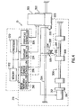
- Shown in Figure 3 is a second view of inkjet printer 10 with cover 200 raised to display a part of the internal mechanism.
- print cartridges of which print cartridge 202 is exemplary, are positioned outside of the media path.
- the print cartridges contain ink of the colors necessary for forming an image on media.
- the print cartridges are moved on a carriage into the media path. Signals are supplied to the print cartridges causing them to eject the color of ink necessary to form the image on the media.
- Carriage 300 holds the print cartridges 302 (the four cartridge colors are shown as a single unit for convenience). Carriage 300 carries print cartridges 302 along guide 304. Not shown in Figure 4 (to simplify the illustration) is a belt coupled to carriage 300 that moves carriage 300 on guide 304 during the placement of ink onto units of paper 12. The movement of carriage 300 across the media is carefully controlled so that ink ejected from print cartridges 302 is precisely placed on units of paper 12.
- Each of the cartridges include in print cartridges 302 includes an embodiment of a printhead, printhead 303.
- the printhead includes resistive elements associated with a corresponding array of nozzles.
- Units of paper 12 are moved into a print zone (the region along the media path in which print cartridges can direct ink onto media) by an embodiment of a media drive mechanism, media drive mechanism 306.
- Media drive mechanism 306 includes drive rollers, of which drive roller 308 is exemplary.
- media drive mechanism 306 includes pinch rollers (represented in Figures 5A and 5B for simplicity of illustration as exemplary pinch rollers 310).
- Units of paper are moved by pick roller 106 out of input tray 14. The leading edge of units of paper 12 move through the nip region formed between the pinch rollers.
- a circularly shaped guide (not shown in Figure 4 for simplicity of illustration) forces units of paper 12 to wrap around the drive rollers to guide it into the nip region between the pinch rollers.
- Units of paper 12 enter the print zone when the leading edge is moved below print cartridges 302 and over a flat member (shown in Figure 5A and 5B as pivot 311).
- a motor such as servo motor 312, is coupled to shaft 314 on which the drive rollers are mounted.
- An encoder such as rotary position encoder 316 is coupled to a shaft of servo motor 312.
- Rotary position encoder 316 is used to count the number of steps servo motor 312 rotates in response to a command. The steps are generally some predetermined fraction of a single rotation of the shaft of servo motor 312. The size of the rotational steps will depend on the maximum resolution with which it is desired to make incremental movements of media.
- the use of rotary position encoder 316 allows precise distance movements of units of paper 12.
- Rotary position encoder 316 allows counting of the number of incremental movements performed by servo motor 312.
- Media movement controller 318 generates the signals applied to servo motor 312 to perform a movement of units of paper 12 a predetermined distance.
- Servo motor 312, rotary position encoder 316, media movement controller 318, the drive rollers, and the pinch rollers are included in media movement mechanism 319 used to control the forward and backward movement of units of paper 12 in the media path.
- a processing device such as processor 320, executes firmware stored in memory 322. The moves that media movement controller 318 commands servo motor 312 to perform are based upon commands received by media movement controller 318 from processor 320 executing the firmware stored in memory 322.
- processor 320 In commanding a move of a specific distance at a specific velocity, processor 320 monitors the count provided by rotary position encoder 316 to determine when to begin deceleration to perform a move of the desired distance.
- Carriage controller 324 controls the movement of carriage 300 by controlling the rotation of another servo motor (not shown in Figure 4) based upon commands received from processor 320 through the execution of firmware.
- Carriage 300 is moved across the media path during each printing swath so that ink can be ejected from print cartridges 302 at the necessary locations on units of paper 12 to form images.
- Printhead controller 326 generates the signals used by print cartridges 302 to eject ink at the correct location on units of paper 12.
- Processor 320 is coupled to printhead controller 326 and provides the print data used by printhead controller 326 to generate the signals supplied to print cartridges 302.
- Inkjet printer 10 includes first sensor, such as media sensor 328, and a second sensor, such as optical sensor 330.
- Media sensor 328 detects the presence of units of paper 12 or other media at the location in the media path corresponding to the position of media sensor 328 in the media path.
- Optical sensor 330 is used to measure the intensity of the diffuse lightreflected from the surface of media.
- Optical sensor 330 is used for the calibration and alignment of print cartridges 302.
- optical sensor 330 is used to measure the performance of inkjet printer 10 in forming images on media.
- optical sensor 330 is used in an embodiment of the media movement apparatus to determine the position of the leading edge of units of paper 12 or other types of media.
- Media sensor 328 detects edges of units of paper 12 or other types of media using lever 332 and an optical emitter/detector 334.
- Media sensor 328 is positioned inside of the media path.
- the optical emitter/detector 334 does not detect reflected light.
- the detector in optical emitter/detector 334 generates a signal indicating that no light has been detected.
- the signal generated by optical emitter/detector 334 is coupled to sensor controller 336.
- Sensor controller 336 generates digital signals that are supplied to processor 320.
- Sensor controller 336 interprets the signal indicating no detection of light as the absence of units of paper 12 at lever 332.
- processor 320 polls sensor controller 336 to determine the state of the sensors. As will be described in more detail later, the states of the sensors will be used in the embodiment of the media movement apparatus.
- lever 332 When the leading edge of a unit of paper 12 contacts lever 332, it rotates about pivot 338.
- lever 332 rotates after contacting the leading edge of a unit of paper 12, light is reflected off lever 332 and detected by optical emitter/detector 334.
- emitter/detector 334 In response, emitter/detector 334 generates a signal indicating that light has been detected.
- Sensor controller 336 interprets this signal to indicate the presence of a unit of paper 12 at lever 332 and generates a digital signal indicating that media sensor 328 has detected a unit of paper 12.
- lever 332 rotates back into its position without units of paper 12 in the media path.
- sensor controller 336 generates a digital signal indicating that media sensor 328 does not detect the presence of a unit of paper 12.
- media sensor 328 is of a mechanical-optical type, it should be recognized that other types of sensors could be used. For example, a sensor having an optical emitter/detector positioned above and below the media path could be used. The important functional characteristic of media sensor 328 is its ability to detect the presence or absence of media at a location in the media path. In addition, although media sensor 328 is positioned near the edge of the media path, it could be located at other positions across the width of the media path.
- Optical sensor 330 is used to measure light reflected from the surface of units of paper 12 for a calibration and alignment of print cartridges 302. Performing this alignment involves the placement of a pattern on a unit of paper 12 and measuring the intensity of light reflected from the surface. For purposes of performing the calibration and alignment, optical sensor 330 measures diffuse and specular light reflected from the surface of units of paper 12. Optical sensor 330 generates analog signals corresponding to the measured specular and diffuse reflected light. The analog signals are converted to digital signals by an analog to digital (A/D) converter included within sensor controller 336. The output of the A/D converter represents the intensity of the reflected light measured by optical sensor 330. As will be discussed in more detail below, optical sensor 330 is used in an embodiment of the media movement apparatus to detect the presence of media at the location of optical sensor 330 within the media path.
- A/D analog to digital
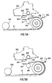
- Figure 5A and Figure 5B Shown in Figure 5A and Figure 5B are simplified views of components associated with the media path in inkjet printer 10.
- Figure 5Aa and Figure 5B are included for the purpose of illustrating the spatial relationship between pick roller 106, media sensor 328, optical sensor 330, drive roller 308, pinch roller 310, and pivot 311.
- Figure 5A shows the position of lever 332 before contact by the leading edge of a unit of paper 12.
- Figure 5B shows the position of lever 332 after contact by the leading edge of a unit of paper 12.
- Guide 340 directs units of paper 12 around the circumference of the drive rollers and into the nip region between the pinch rollers.
- processor 320 After a unit of paper 12 is moved into the media path, processor 320, under firmware control, begins polling sensor controller 336 to determine if media sensor 328 has detected the presence of a unit of paper 12. The position of the unit of paper 12 in the media path when media sensor 328 first indicates the presence of the unit of paper 12 establishes the position of the leading edge. When the polling of sensor controller 336 by processor 320 indicates that media is present at lever 332, then processor 320 signals media movement controller 318 to stop rotation of servo motor 312. The more rapidly sensor controller 336 is polled, the more accurately the position of the leading edge of the unit of paper 12 can be ascertained. Polling every 1.6 ms has been found to locate the leading edge with sufficient accuracy.
- processor 320 After determining the leading edge position of the unit of paper 12, processor 320 commands media movement controller 318 to rotate servo motor 312 to advance the unit of paper 12 in the media path a predetermined distance.
- This predetermined distance corresponds to the distance necessary to move the leading edge of the unit of paper 12 to the input side of the print zone.
- the imaging operation in the first mode is performed by advancing the unit of paper 12 to a location in the print zone corresponding to the image that will be formed on that swath of the unit of paper 12, moving carriage 300 and print cartridges 302 across the swath while ejecting ink to form the image on that swath, and then advancing the unit of paper 12 in the media for forming the image on the next swath.
- Operation in the second mode provides a substantial improvement in the throughput at which images can formed on units of paper 12.
- the spacing between successive units of paper 12 is variable.
- Media jams may occur because the media ejection process used for the first mode of operation does not work in the second mode of operation.
- Media jams are avoided by rapidly moving a unit of media upon which imaging has been performed out of the media path.
- Another difficulty arising in performing imaging operations in the second mode is in locating the leading edge and the trailing edge.
- Performing imaging operations in the second mode does not rely exclusively upon media sensor 328 to locate the leading edge of units of paper 12.
- the gap between successive units of paper 12 while operating in the second mode will be, in many cases, too small to permit the trailing edge of the earlier unit of paper 12 or the leading edge of the later unit of paper 12 to be detected by media sensor 328 because lever 332 will not rotate sufficiently in the gap between units of paper 12 to generate a change in the signal supplied to sensor controller 336. Therefore, for imaging operations performed in the second mode, the trailing edge and the leading edge of units of paper 12 will be detected in a different way.
- the decision to perform imaging operations in the first mode or the second mode is made by processor 320 according to information received from driver software operating in a computer.
- driver software operating in a computer.
- an imaging operation is started after a user generates data in an application program or opens a file using the application program.
- the driver software is executed when the user elects to print the data generated in the application.
- information specifying the number of units of media upon which images will be formed is passed to processor 320.
- processor 320 would decide to operate in the second mode if three or more units of media were included in the imaging operation. However, processor 320 cannot make a decision regarding operation in either the first mode or the second mode until information relating to the number of units in the imaging operation is passed to processor 320 from the computer executing the driver software. The time at which this information is passed depends upon the operating system of the computer. The information is supplied by the driver operating within the computer. The information corresponds to the number of pages in the imaging operation that have been rendered by the driver.
- the drivers operating in different operating systems may report the rendering of pages differently.
- the number of pages in imaging operation is rendered and then reported.
- the firmware executing in processor 320 makes a determination to operate in the first or second mode using the information supplied by the driver. To correctly make the decision to operate in the first mode or the second mode in the WINDOWS 98 operating system the firmware checks both the number of pages rendered by the driver and a flag indicating completion of the rendering operation by the driver on all pages on which images will be formed.
- inkjet printer 10 For example, if the driver operating in WINDOWS 98 reported that 2 pages had been rendered, but the rendering operation was not complete, then the firmware would decide to operate in the second mode.
- the default mode in which inkjet printer 10 performs imaging operations is the first mode. Until processor 320 decides that imaging operations should be performed in the second mode, inkjet printer 10 operates in the first mode.
- Operation in the second mode is only performed on imaging operations using letter size paper or A4 size paper. Because of this, the decision to operate in the second mode is made after an imaging operation is performed on the first unit of paper 12 in the imaging operation and the length of the first unit of paper 12 can be measured.
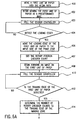
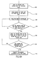
- Shown in Figure 6A through Figure 6H is a high level flow diagram corresponding to an exemplary imaging operation in inkjet printer 10 performed using the second mode.
- a first unit of paper 12 is moved into the media path.
- step 402 processor 320 commands media movement controller 318 to begin a moving the first unit of paper 12 up to a predetermined distance at a predetermined rate (in one embodiment of the media movement apparatus the move can correspond to up to 30,000 counts of rotary position encoder 316 at 50.8 cm (20 inches) per second).
- processor 320 polls sensor controller 336.
- step 404 processor 320 determines if media sensor 328 has detected the leading edge of the first unit of paper 12. If it has not, then control is returned to step 403.
- processor 320 commands media movement controller 318 to move the first unit of paper 12 an additional predetermined distance from the location at which the leading edge was detected to bring the leading edge to the input side of the print zone (in one embodiment of the media movement apparatus this additional predetermined distance corresponds to 4500 counts of rotary position encoder 316). Then in step 407, processor 320 establishes the rotary position encoder count at the location where the leading edge of the first unit of paper 12 is at the input side of the print zone.
- inkjet printer 10 begins forming image is formed on the first unit of paper 12 corresponding to data generated by an application program executed on a computer by moving carriage 300 across the media path and ejecting ink from print cartridges 302 onto the first unit of paper 12.
- processor 320 While formation of the image on the first unit of paper 12 is underway, processor 320, in step 410, polls sensor controller 336. In step 412, processor determines if the trailing edge of the first unit of paper 12 has been detected from the results of polling sensor controller 336. If the trailing edge is not detected, control is returned to step 410 to continue to poll sensor controller 336 while the image continues to be formed on the first unit of paper 12 is underway.
- the region on units of paper 12 on which ink can be placed is the imaging zone. There are four boundaries for the imaging zone. The two boundaries of the imaging zone that are substantially perpendicular to the direction of the media path will be referred to as the leading edge and the trailing edge of the imaging zone.
- processor 320 determines, in step 414, the number of counts of rotary position encoder 316 (that is, incremental rotational movements of servo motor 312) until the trailing edge of the imaging zone reaches the output side of the print zone.
- processor 320 polls media movement controller 318 to receive the count from rotary position encoder 316. Then, in step 418, processor 320 determines if the trailing edge of the imaging zone on the first unit of paper 12 has reached the output side of the print zone. If the trailing edge of the imaging zone has not reached the output side of the print zone, then control is returned to step 416. If the trailing edge of the imaging zone has reached the output side of the print zone, then, in step 420, processor 320 stops the formation of the image on the first unit of paper 12. Next, in step 422, processor 320 determines the length of the first unit of paper 12 using the encoder counts corresponding to detection of the leading edge and the trailing edge by media sensor 328.
- predetermined count values (representing the media lengths) corresponding to each of the types media used.
- the media type (and the length of the media type in terms of count values) on which the imaging operation will be performed is determined by determining which of the predetermined count values is with + /- 500 counts of the measured length of the first unit of paper 12.
- the first unit of paper 12 is ejected into output tray 16.
- step 425 processor determines that the imaging operation should be performed in the second mode using the information supplied by the driver and causes member 104 to move out of contact with pressure plate 102 to enter the second mode of operation.
- media movement controller 318 begins moving a second unit of paper 12 through the media path. This movement can be up to a predetermined distance.
- step 428 processor 320 polls sensor controller 336 as the second unit of paper 12 moves through the media path.
- step 430 processor 320 determines if the leading edge of the second unit of paper 12 has been detected. If the leading edge is not detected control is returned to step 428.
- step 432 the second unit of paper 12 is moved a predetermined distance until the leading edge of the imaging zone is at the input side of the print zone.
- step 434 processor 320 determines the count of rotary position encoder 316 at which the trailing edge of the imaging zone on the second unit of paper 12 will reach the output side of the print zone of print cartridges 302. This is done using the predetermined number of counts for the length of the media type used, the known distance, in terms of counts of rotary position encoder 316, between the location at which media sensor 328 detects the leading edge and the output side of the print zone, and the count of rotary position encoder 316 when the leading edge of the second unit of paper 12 is detected.
- each of the units of paper 12 is of the same size class, for example, letter size paper.
- the time at which the trailing edge of the imaging zone of the second unit of paper 12 is at the output side of the print zone is determined this manner because media sensor 328 cannot be relied upon to sense the trailing edge of the second unit of paper 12 in the second mode of operation.
- inkjet printer 10 begins forming an image on the second unit of paper 12 corresponding to data generated by an application program executed on a computer by moving carriage 300 across the media path and ejecting ink from print cartridges 302 onto the second unit of paper 12 while the second unit of paper 12 is being advanced through the print zone.
- media movement controller 318 begins moving a third unit of paper 12 is moved into the media path. While the image is formed on the second unit of paper 12, processor 320, in step 440, polls media movement controller 318 to receive the count supplied by rotary position encoder 316.
- step 442 processor 320 determines if the trailing edge of the imaging zone on the second unit of paper 12 has reached the output side of the print zone for print cartridges 302. If the trailing edge of the imaging zone on the second unit of paper 12 has not reached the output side of the print zone, control is returned to step 440.
- processor 320 stops forming an image on the second unit of paper 12. Then, in step 446, processor 320 commands media movement controller 318 to begin moving the second unit of paper 12 and the third unit of paper 12 at the high speed of the velocity profiles shown in Figure 7.
- the velocity profile shown in Figure 7 permits ejection of the second unit of paper 12 while preventing contact with the third unit of paper 12.
- the speed in region 600 depends upon the fraction of the length of the imaging zone upon which ink is placed. If ink is placed on a large fraction of the length of the imaging zone, then the units of paper 12 are moved at 76.2 cm (30 inches) per second.
- the units of paper 12 are moved at 63.5 cm (25 inches) per second.
- the media movement apparatus with less than 22 millimeters remaining until the trailing edge of the unit of paper 12 reaches the pinch roller movement is done at 76.2 cm (30 inches) per second. With 22 millimeters or more remaining movement is done at 63.5 cm (25 inches) per second.
- processor 320 polls media movement controller 318. Then, in step 450, processor 320 determines (by looking at counts from rotary position encoder 316) if the trailing edge of the second unit of paper 12 reaches the nip region between the pinch rollers using the count of rotary position encoder 316 obtained from media movement controller 318 at the detection of the leading edge of the second unit of paper 12, the length of the second unit of paper 12, and the known distance from lever 332 of media sensor 328 to the nip region. If the trailing edge of the second unit of paper 12 has not reached the nip region, control is returned to step 448.
- processor 320 commands, in step 452, media movement controller 318 to decelerate movement of the third unit of paper 12 at the rate shown in region 602.
- the rate at which the deceleration occurs is determined empirically to allow the second unit of paper 12 to move out of the media path.
- processor 320 polls media movement controller 318 to determine the count of rotary position encoder 316.
- processor 320 determines if the third unit of paper 12 has moved a predetermined distance corresponding to a predetermined number of counts of rotary position encoder 316. If it has not, control is returned to step 454. If the third unit of paper 12 has moved the predetermined distance, then, in step 458, processor 320 commands media movement controller 18 to stop the movement of the third unit of paper 12.
- the speed in region 600 moves the second unit of paper 12 sufficiently fast so that its momentum carries it into output tray 16 without requiring the use of the media ejection mechanism.
- the deceleration rate region 602 is done to permit the second unit of paper 12 to move toward the output tray without contacting the third unit of paper 12 following closely behind it. Contact between successive units of paper 12 in the media path increases the likelihood that a media jam can result.
- the deceleration rate shown in Figure 7 is empirically determined from the objective of having the third unit of paper 12 gently contact the second unit of paper 12 as it is ejected from the media path. The speed profile could achieve the desired objectives with a wide range of media acceleration and deceleration rates.
- inkjet printer 10 uses a particular speed in region 600 and a particular deceleration rate in region 602, it should be recognized that other speed profiles may be used.
- the important characteristic of the speed profile is that it imparts sufficient momentum to units of media to move them into the output tray while reducing the likelihood of a strong impact between successive units of media in the media path.
- the mechanical configuration of other printers may make a different velocity profile appropriate.
- a first possibility is that there is a gap of sufficient width between these units of paper 12 so that the leading edge of the third unit of paper 12 does not move beneath the optical sensor 330 (located within the print zone) after movement of the third unit of paper 12 is stopped.
- a second possibility is that the gap between these units of paper 12 is sufficiently small so that the leading edge of the third unit of paper 12 is in the print zone after movement of the third unit of paper 12 is stopped.
- a third possibility is that there is sufficient overlap between the second unit of paper 12 and the third unit of paper 12 so that executing the move associated with the speed profile of Figure 7 pushes the leading edge of the third unit of paper 12 well beyond the input side of the print zone of print cartridges 302.
- the second possibility is the most frequently occurring.
- the firmware initially operates assuming that the second possibility has occurred. For this case, the leading edge of the third unit of paper 12 has moved within the range that can be detected by optical sensor 330.
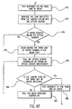
- the firmware controlling processor 320 commands media movement controller 318 to begin moving the third unit of paper 12 backwards in the media path.
- processor 320 polls sensor controller 336 to obtain the output from optical sensor 330.
- the value returned from optical sensor 330 will be close to the maximum possible value (a value of 256 for an embodiment of optical sensor 330 that could be used in inkjet printer 10).
- the value returned from optical sensor 330 will be close to the minimum possible value (a value of 0).
- processor 320 determines if the leading edge of the third unit of paper 12 has been detected using the collected values of the output from optical sensor 330.
- the position of the leading edge is determined as the position of the third unit of paper 12 when the value generated by optical sensor 330 decreases by a value of 50.
- processor 320 polls media movement controller 318.
- processor 320 determines if the third unit of paper 12 has moved a predetermined distance backward in the media path.
- the predetermined distance corresponds to 1500 counts of rotary position encoder 316. If the third unit of paper 12 has not moved the predetermined distance backward, then control is returned to step 462. If the third unit of paper 12 has moved the predetermined distance, then, in step 470, processor 320 commands media movement controller 318 to stop movement of the third unit of paper 12.
- step 472 movement of the third unit of paper 12 is stopped and then control is transferred to step 502. !f in step 468, processor 320 determines that the third unit of paper 12 moves backward in the paper path the distance corresponding to the predetermined number of counts without detecting the leading edge of the third unit of paper 12, then there are two primary options corresponding to the previously mentioned first possibility and third possibility.
- the first possibility is that the gap between the second unit of paper 12 and the third unit of paper 12 was sufficiently large so that after completion of the move associated with the speed profile of Figure 7, the leading edge of the third unit of paper 12 was behind optical sensor 330 in the media path.
- the third possibility is that the leading edge of the third unit of paper 12 had advanced so far in the media path that the movement backward the maximum distance was not sufficient to place the leading edge behind optical sensor 330 in the media path (as would occur when the third unit of paper 12 overlapped the second unit of paper 12), thereby preventing detection of the leading edge.
- step 472 the firmware controlling processor 320 polls sensor controller 336. Then, in step 474, processor 320 determines if the third unit of paper 12 is present below optical sensor 330. If the value corresponds to the presence of the third unit of paper 12 (at the high end of the 0 to 256 range), then it is likely that there was overlap between the second unit of paper 12 and the third unit of paper 12. If the third unit of paper 12 is below optical sensor 330, then control is transferred to step 500 because there was overlap between the second unit of paper 12 and the third unit of paper 12.
- processor 320 commands media movement controller 318 to begin moving the third unit of paper 12 forward in the media path up to a predetermined distance so that the leading edge of the third unit of paper 12 is likely pass beneath optical sensor 330.
- this predetermined distance is empirically determined to correspond to a move of 30,000 counts of rotary position encoder 316.
- the gap between successive units of paper 12 will almost always be much less than this. Typically, the gap between successive units of paper 12 will not exceed the circumference of the drive roller in inkjet printer 10.
- step 478 processor 320 polls optical sensor controller 336 to obtain the measurement generated by optical sensor 330.
- step 480 processor 320 determines if the leading edge of the third unit of paper 12 has been detected. If the leading edge of the third unit of paper 12 is detected, then, in step 482, movement of the third unit of paper 12 is stopped and then control is transferred to step 490. If the leading edge of the third unit of paper 12 is not detected, then, in step 484, processor 320 polls media movement controller 318 to obtain a value from rotary position encoder 316. Next, in step 486, processor 320 determines if the third unit of paper 12 has moved the predetermined distance forward in the media path. If it has not, control is returned to step 478.
- step 488 processor stops attempting to move of the third unit of paper 12 and signals that there is a media jam.
- step 490 processor 320 commands media movement controller 318 to begin moving the third unit of paper 12 forward in the media path a predetermined distance.
- this predetermined distance corresponds to 900 counts of rotary position encoder 316.
- processor 320 polls media movement controller 318.
- step 494 processor 320 determines if the third unit of paper 12 has moved forward the predetermined distance. If it has not, then control is returned to step 492.
- this predetermined distance forward corresponds to 900 additional counts of rotary position encoder 316.
- This additional advance is to move the third unit of paper 12 forward so that the leading edge of the third unit of paper 12 can be located by moving the third unit of paper 12 backward. It is desirable to have the leading edge of units of paper 12 positioned at substantially the same location after detection of the leading edge.
- the edge on the third unit of paper 12 is detected while it is moving backward in the media path. Detecting the leading edge of units of paper 12 while moving backward is done in one embodiment of the media movement apparatus because of the characteristics of optical sensor 330.
- Detecting the position of the leading edge with optical sensor 330 while moving the third unit of paper 12 forward in the media path will not provide the same location of the leading edge as when detection is done while moving the third unit of paper 12 backward in the media path. It should be recognized that with a different kind of optical sensor, detection of the leading edge may be done with units of paper 12 moving either forward or backward in the media path. If, in step 494, processor 320 determines that the third unit of paper 12 has been moved forward the predetermined distance, then control is returned to step 460.
- step 464 If, in step 464, the leading edge of the third unit of paper 12 is detected while moving it backward, then control is transferred to step 496.
- processor 320 commands media movement controller 318 to move the leading edge of the third unit of paper 12 to the input side of the print zone.
- the distance from the location at which the leading edge is located using optical sensor 330 to the input side of the print zone of print cartridges 302 is available to the firmware as a predetermined value for inkjet printer 10.
- step 498 an image is formed on the third unit of paper 12.
- step 500 the firmware executing in processor 320 moves member 104 into contact with pressure plate 102 and commands media movement controller 318 to move all units of paper 12 in the media path into output tray 16.
- step 502 processor 320 commands media movement controller 318 to begin moving the third unit of paper 12 out of the media path. While the media path is clearing, in step 504, processor 320 polls sensor controller 336 to detect the trailing edge of the third unit of paper 12.
- processor 320 determines if the trailing edge of the third unit of paper 12 has been detected. If it has not, control is transferred to step 504. If the trailing edge has been detected, then in step 508, processor 320 commands media movement controller 318 to move the trailing edge of the third unit of paper to the nip region between the pinch rollers and eject it in to the output tray.
- processor 320 determines whether imaging on the remaining units in the imaging operation will be performed in the second mode. If the imaging operation is to be done in the first mode, in step 512, the imaging operation is completed in the first mode. If the imaging operation is to be completed in the second mode, control is returned to step 426.
Landscapes
- Ink Jet (AREA)
- Accessory Devices And Overall Control Thereof (AREA)
- Handling Of Sheets (AREA)
- Controlling Sheets Or Webs (AREA)
Claims (7)
- Ein Verfahren zum Lokalisieren einer Kante eines Mediums (12) in einer Tintenstrahlbilderzeugungsvorrichtung (10), die einen Medienweg aufweist, das folgende Schritte aufweist:Bewegen (460) des Mediums (12) rückwärts in dem Medienweg;Vornehmen (462) einer Mehrzahl von Messungen von Licht, das von innerhalb des Medienwegs reflektiert wird, während des rückwärts Bewegens des Mediums (12); undAnhalten (472) einer Bewegung des Mediums (12), falls die Mehrzahl von Messungen eine Erfassung der Kante angibt.
- Das Verfahren gemäß Anspruch 1, das ferner folgende Schritte aufweist:Bewegen (490) des Mediums (12) vorwärts in dem Medienweg nach einem Erfassen der Kante; undAnhalten (470) einer Bewegung des Mediums (12), falls sich das Medium eine vorbestimmte Strecke in dem Medienweg ohne eine Erfassung der Kante rückwärts bewegt.
- Das Verfahren gemäß Anspruch 2, das ferner folgende Schritte aufweist:Vornehmen (472) einer Messung des Lichts, das von innerhalb des Medienwegs reflektiert wird, falls das Medium (12) sich die vorbestimmte Strecke in dem Medienweg rückwärts bewegt;Bewegen (476) des Mediums vorwärts in dem Medienweg, falls sich das Medium (12) die vorbestimmte Strecke in dem Medienweg rückwärts bewegt und die Messung das Nichtvorhandensein des Mediums (12) angibt;Vornehmen (478) einer zweiten Mehrzahl von Messungen des Lichts, das von innerhalb des Medienwegs reflektiert wird, während das Medium (12) bewegt wird, wobei die Mehrzahl von Messungen einer ersten Mehrzahl von Messungen entspricht; undBewegen (490) des Mediums (12) vorwärts um eine zweite vorbestimmte Strecke, falls die zweite Mehrzahl von Messungen eine Erfassung der Kante angibt, wobei die vorbestimmte Strecke einer ersten vorbestimmten Strecke entspricht.
- Das Verfahren gemäß Anspruch 3, das ferner folgende Schritte aufweist:Bewegen (502) des Mediums aus dem Medienweg, falls das Medium (12) sich in dem Medienweg die erste vorbestimmte Strecke ohne eine Erfassung der Kante rückwärts bewegt und die Messung das Vorhandensein des Mediums (12) angibt; undAnhalten (488) einer Bewegung des Mediums (12) und Signalisieren einer Fehlerbedingung, falls sich das Medium (12) eine dritte vorbestimmte Strecke ohne eine Erfassung der Kante vorwärts bewegt.
- Das Verfahren gemäß Anspruch 4, das ferner folgende Schritte aufweist:Bewegen (460) des Mediums rückwärts in dem Medienweg nach einem Bewegen um die zweite vorbestimmte Strecke;Vornehmen (462) einer dritten Mehrzahl von Messungen des Lichts, das von innerhalb des Medienwegs reflektiert wird, während des Bewegens des Mediums (12);Anhalten (472) einer Bewegung des Mediums (12), falls die dritte Mehrzahl von Messungen eine Erfassung der Kante angibt;Bewegen (496) des Mediums (12) eine vierte vorbestimmte Strecke vorwärts, falls die erste Mehrzahl von Messungen oder die dritte Mehrzahl von Messungen die Kante erfasst; undErzeugen eines Bilds an dem Medium (12).
- Eine Vorrichtung, um eine Kante eines Mediums (12) in einer Tintenstrahlbilderzeugungsvorrichtung (10) zu lokalisieren, die folgende Merkmale aufweist:einen Sensor (330), der konfiguriert ist, um Licht zu messen, das von dem Medium (12) reflektiert wird;einen Medienbewegungsmechanismus (319), der konfiguriert ist, um das Medium (12) in einem Medienweg rückwärts zu bewegen; undeine Verarbeitungsvorrichtung (320), die angeordnet ist, um eine Mehrzahl von Messungen von Licht, das von innerhalb des Medienwegs reflektiert wird, von dem Sensor (330) zu empfangen, während in Gebrauch das Medium (12) rückwärts in dem Medienweg bewegt wird, und konfiguriert ist, um dem Medienbewegungsmechanismus (319) zu befehlen, eine Bewegung des Mediums (12) anzuhalten, falls in Gebrauch die Mehrzahl von Messungen eine Erfassung einer Kante des Mediums (12) angibt.
- Eine Bilderzeugungsvorrichtung (10), die folgende Merkmale aufweist:einen Druckkopf (303), um Tinte auf ein Medium (12) auszustoßen;eine Druckkopfsteuerung (326), die konfiguriert ist, um ein Signal zu dem Druckkopf (303) zu liefern, um Tinte gemäß Bilddaten auszustoßen; unddie Vorrichtung gemäß Anspruch 6.
Applications Claiming Priority (2)
| Application Number | Priority Date | Filing Date | Title |
|---|---|---|---|
| US651698 | 2000-08-30 | ||
| US09/651,698 US6435641B1 (en) | 2000-08-30 | 2000-08-30 | Media movement apparatus |
Publications (3)
| Publication Number | Publication Date |
|---|---|
| EP1184189A2 EP1184189A2 (de) | 2002-03-06 |
| EP1184189A3 EP1184189A3 (de) | 2002-10-16 |
| EP1184189B1 true EP1184189B1 (de) | 2007-06-06 |
Family
ID=24613856
Family Applications (1)
| Application Number | Title | Priority Date | Filing Date |
|---|---|---|---|
| EP01307113A Expired - Lifetime EP1184189B1 (de) | 2000-08-30 | 2001-08-21 | Druckträgertransportvorrichtung |
Country Status (3)
| Country | Link |
|---|---|
| US (1) | US6435641B1 (de) |
| EP (1) | EP1184189B1 (de) |
| DE (1) | DE60128757T2 (de) |
Families Citing this family (18)
| Publication number | Priority date | Publication date | Assignee | Title |
|---|---|---|---|---|
| JP3762228B2 (ja) * | 2001-01-31 | 2006-04-05 | キヤノン株式会社 | 記録装置および記録方法 |
| US6779868B2 (en) * | 2001-07-06 | 2004-08-24 | Benq Corporation | Printer with a calibration position positioned within a printing range |
| US6637852B2 (en) * | 2002-01-24 | 2003-10-28 | Hewlett-Packard Company | Method for media handling in an imaging device |
| KR100449019B1 (ko) * | 2002-08-06 | 2004-09-18 | 삼성전자주식회사 | 여백없는 인쇄를 위한 용지에지 검출장치 및 방법 |
| US6830328B2 (en) * | 2002-11-05 | 2004-12-14 | Oki Data Americas, Inc. | Combination input and output tray assembly for a printing device |
| US6850264B2 (en) * | 2003-01-28 | 2005-02-01 | Fujifilm Electronic Imaging Limited | Edge detection apparatus and method |
| US7063018B2 (en) * | 2003-05-23 | 2006-06-20 | Eastman Kodak Company | Method and apparatus for detecting the edge of an imaging media |
| US20050248644A1 (en) * | 2003-07-02 | 2005-11-10 | Lexmark International, Inc. | Method for enhancing perforation speed |
| US7410317B2 (en) * | 2003-08-26 | 2008-08-12 | Oki Data Corporation | Method for processing medium, image processing apparatus, and printer apparatus |
| US7393075B2 (en) * | 2003-09-05 | 2008-07-01 | Canon Kabushiki Kaisha | Recording apparatus, and feed control method of recording medium in the apparatus |
| US7778589B2 (en) * | 2004-11-30 | 2010-08-17 | Hewlett-Packard Development Company, L.P. | Method and apparatus for sheet handling in an imaging device |
| US7753371B2 (en) * | 2005-12-12 | 2010-07-13 | Hewlett-Packard Development Company, L.P. | Media jam and bent corner detector |
| US20090283565A1 (en) * | 2008-05-19 | 2009-11-19 | Jose Miguel Ibanez | Determination of roll media dimensions |
| US8579430B2 (en) * | 2009-07-31 | 2013-11-12 | Zamtec Ltd | Wide format printer with aerosol collection from both sides of media path |
| JP5729946B2 (ja) * | 2010-08-27 | 2015-06-03 | キヤノン株式会社 | インクジェット記録装置 |
| US9132672B2 (en) * | 2011-11-08 | 2015-09-15 | Xerox Corporation | Controlling exit velocity of printed sheets being stacked to optimize stack quality |
| US9145011B2 (en) * | 2013-01-31 | 2015-09-29 | Hewlett-Packard Development Company, L.P. | Printing system with force control mode |
| JP6160384B2 (ja) * | 2013-09-13 | 2017-07-12 | セイコーエプソン株式会社 | 画像記録装置 |
Family Cites Families (12)
| Publication number | Priority date | Publication date | Assignee | Title |
|---|---|---|---|---|
| US5252991A (en) | 1991-12-17 | 1993-10-12 | Hewlett-Packard Company | Media edge sensor utilizing a laser beam scanner |
| EP0622230A3 (de) | 1993-04-30 | 1995-07-05 | Hewlett Packard Co | Verfahren zum bidirektionalen Drucken. |
| JPH08142433A (ja) * | 1994-11-18 | 1996-06-04 | Seiko Epson Corp | 印字方法およびその方法を用いたプリンタ |
| US5466079A (en) | 1995-01-27 | 1995-11-14 | Hewlett-Packard Company | Apparatus for detecting media leading edge and method for substantially eliminating pick skew in a media handling subsystem |
| US5580046A (en) | 1995-01-31 | 1996-12-03 | Hewlett-Packard Company | Selective ejection of sensed paper jams in single sheet paper processing equipment |
| US5563686A (en) | 1995-01-31 | 1996-10-08 | Hewlett-Packard Company | Input paper sensor for single sheet paper processing equipment |
| US5521674A (en) | 1995-08-22 | 1996-05-28 | Hewlett-Packard Company | System and method for controlling a printer device |
| JPH09235033A (ja) * | 1995-12-26 | 1997-09-09 | Tohoku Ricoh Co Ltd | 給紙装置 |
| US5969371A (en) | 1996-08-29 | 1999-10-19 | Hewlett-Packard Company | Method and apparatus for finding media top-of-page in an optical image scanner |
| US5856833A (en) | 1996-12-18 | 1999-01-05 | Hewlett-Packard Company | Optical sensor for ink jet printing system |
| US6005683A (en) | 1997-12-05 | 1999-12-21 | Hewlett-Packard Company | Document edge detection by linear image sensor |
| US6325559B1 (en) * | 2000-06-02 | 2001-12-04 | Hewlett-Packard Company | Single transmission state media handling for ejecting, picking and loading |
-
2000
- 2000-08-30 US US09/651,698 patent/US6435641B1/en not_active Expired - Fee Related
-
2001
- 2001-08-21 DE DE60128757T patent/DE60128757T2/de not_active Expired - Lifetime
- 2001-08-21 EP EP01307113A patent/EP1184189B1/de not_active Expired - Lifetime
Also Published As
| Publication number | Publication date |
|---|---|
| DE60128757D1 (de) | 2007-07-19 |
| DE60128757T2 (de) | 2008-03-13 |
| EP1184189A3 (de) | 2002-10-16 |
| EP1184189A2 (de) | 2002-03-06 |
| US6435641B1 (en) | 2002-08-20 |
Similar Documents
| Publication | Publication Date | Title |
|---|---|---|
| EP1184189B1 (de) | Druckträgertransportvorrichtung | |
| US7830564B2 (en) | Method of obtaining correction value of optical sensor and recording apparatus | |
| US8142087B2 (en) | Printing device with paper width detector mounted to carriage and method of controlling the printing device | |
| US20060203028A1 (en) | Apparatus and method for print quality control | |
| JP2008012815A (ja) | 搬送制御装置及び該装置を備えた記録装置、搬送制御方法 | |
| EP2095967B1 (de) | Bildaufzeichnungsvorrichtung und -verfahren | |
| CA1254850A (en) | Paper loading system for use in a printer | |
| US7681974B2 (en) | Recording apparatus and method | |
| CN108454241B (zh) | 印刷装置以及印刷控制方法 | |
| EP0712728B1 (de) | Druckverfahren und Drucker unter Verwendung desselben | |
| US7455380B2 (en) | Printing apparatus, media detection apparatus, media detection method, measurement method, computer-readable storage medium, and printing system | |
| US7591602B2 (en) | Gap detector, liquid ejecting apparatus incorporating the same, and gap detecting method executed in the apparatus | |
| EP3524438B1 (de) | Druckvorrichtung | |
| JP3876734B2 (ja) | 印刷シートの判別装置、印刷装置、コンピュータプログラム、コンピュータシステム、及び、印刷シートの判別方法 | |
| JP2717491B2 (ja) | プリンタ動作方法 | |
| JP2012045860A (ja) | 記録装置および記録方法 | |
| EP1308301B1 (de) | Medienvorderkantensensor | |
| US5856835A (en) | Ink jet print recording apparatus having a single sensor controlling paper feed and print head recovery | |
| JP3951858B2 (ja) | 記録装置、印刷装置、記録方法、プログラム及びコンピュータシステム | |
| US20190217641A1 (en) | Printing apparatus, home position setting method, and recording medium | |
| JP4032886B2 (ja) | 傾き検出装置及び傾き検出方法 | |
| JP2002254780A (ja) | プリンタ制御装置及びプリンタ制御方法 | |
| US20230202214A1 (en) | Printing apparatus | |
| JP3952827B2 (ja) | 給紙装置、給紙装置を備えた記録装置及び給紙方法 | |
| JP2004160844A (ja) | インクジェット記録装置 |
Legal Events
| Date | Code | Title | Description |
|---|---|---|---|
| PUAI | Public reference made under article 153(3) epc to a published international application that has entered the european phase |
Free format text: ORIGINAL CODE: 0009012 |
|
| AK | Designated contracting states |
Kind code of ref document: A2 Designated state(s): AT BE CH CY DE DK ES FI FR GB GR IE IT LI LU MC NL PT SE TR |
|
| AX | Request for extension of the european patent |
Free format text: AL;LT;LV;MK;RO;SI |
|
| PUAL | Search report despatched |
Free format text: ORIGINAL CODE: 0009013 |
|
| AK | Designated contracting states |
Kind code of ref document: A3 Designated state(s): AT BE CH CY DE DK ES FI FR GB GR IE IT LI LU MC NL PT SE TR |
|
| AX | Request for extension of the european patent |
Free format text: AL;LT;LV;MK;RO;SI |
|
| 17P | Request for examination filed |
Effective date: 20030107 |
|
| AKX | Designation fees paid |
Designated state(s): DE FR GB |
|
| 17Q | First examination report despatched |
Effective date: 20041005 |
|
| GRAP | Despatch of communication of intention to grant a patent |
Free format text: ORIGINAL CODE: EPIDOSNIGR1 |
|
| GRAS | Grant fee paid |
Free format text: ORIGINAL CODE: EPIDOSNIGR3 |
|
| GRAA | (expected) grant |
Free format text: ORIGINAL CODE: 0009210 |
|
| AK | Designated contracting states |
Kind code of ref document: B1 Designated state(s): DE FR GB |
|
| REG | Reference to a national code |
Ref country code: GB Ref legal event code: FG4D |
|
| REF | Corresponds to: |
Ref document number: 60128757 Country of ref document: DE Date of ref document: 20070719 Kind code of ref document: P |
|
| ET | Fr: translation filed | ||
| PLBE | No opposition filed within time limit |
Free format text: ORIGINAL CODE: 0009261 |
|
| STAA | Information on the status of an ep patent application or granted ep patent |
Free format text: STATUS: NO OPPOSITION FILED WITHIN TIME LIMIT |
|
| 26N | No opposition filed |
Effective date: 20080307 |
|
| REG | Reference to a national code |
Ref country code: GB Ref legal event code: 732E Free format text: REGISTERED BETWEEN 20120329 AND 20120404 |
|
| PGFP | Annual fee paid to national office [announced via postgrant information from national office to epo] |
Ref country code: GB Payment date: 20120828 Year of fee payment: 12 |
|
| PGFP | Annual fee paid to national office [announced via postgrant information from national office to epo] |
Ref country code: FR Payment date: 20120830 Year of fee payment: 12 Ref country code: DE Payment date: 20120829 Year of fee payment: 12 |
|
| GBPC | Gb: european patent ceased through non-payment of renewal fee |
Effective date: 20130821 |
|
| PG25 | Lapsed in a contracting state [announced via postgrant information from national office to epo] |
Ref country code: DE Free format text: LAPSE BECAUSE OF NON-PAYMENT OF DUE FEES Effective date: 20140301 |
|
| REG | Reference to a national code |
Ref country code: FR Ref legal event code: ST Effective date: 20140430 |
|
| REG | Reference to a national code |
Ref country code: DE Ref legal event code: R119 Ref document number: 60128757 Country of ref document: DE Effective date: 20140301 |
|
| PG25 | Lapsed in a contracting state [announced via postgrant information from national office to epo] |
Ref country code: GB Free format text: LAPSE BECAUSE OF NON-PAYMENT OF DUE FEES Effective date: 20130821 |
|
| PG25 | Lapsed in a contracting state [announced via postgrant information from national office to epo] |
Ref country code: FR Free format text: LAPSE BECAUSE OF NON-PAYMENT OF DUE FEES Effective date: 20130902 |