EP1184146A2 - Rundtakt-Bearbeitungsmaschine, insbesondere Putzmaschine, für keramische Artikel - Google Patents
Rundtakt-Bearbeitungsmaschine, insbesondere Putzmaschine, für keramische Artikel Download PDFInfo
- Publication number
- EP1184146A2 EP1184146A2 EP01115420A EP01115420A EP1184146A2 EP 1184146 A2 EP1184146 A2 EP 1184146A2 EP 01115420 A EP01115420 A EP 01115420A EP 01115420 A EP01115420 A EP 01115420A EP 1184146 A2 EP1184146 A2 EP 1184146A2
- Authority
- EP
- European Patent Office
- Prior art keywords
- tool
- turntable
- processing
- processing machine
- machine according
- Prior art date
- Legal status (The legal status is an assumption and is not a legal conclusion. Google has not performed a legal analysis and makes no representation as to the accuracy of the status listed.)
- Withdrawn
Links
- 239000000919 ceramic Substances 0.000 title claims abstract description 25
- 238000004140 cleaning Methods 0.000 title claims description 9
- 238000003754 machining Methods 0.000 claims description 7
- 238000001514 detection method Methods 0.000 claims 1
- 238000003801 milling Methods 0.000 description 7
- 238000000034 method Methods 0.000 description 2
- 239000000969 carrier Substances 0.000 description 1
- 230000000052 comparative effect Effects 0.000 description 1
- 238000010586 diagram Methods 0.000 description 1
- 238000005516 engineering process Methods 0.000 description 1
- 239000011159 matrix material Substances 0.000 description 1
- 230000003287 optical effect Effects 0.000 description 1
- 229910052573 porcelain Inorganic materials 0.000 description 1
Images

Classifications
-
- B—PERFORMING OPERATIONS; TRANSPORTING
- B28—WORKING CEMENT, CLAY, OR STONE
- B28B—SHAPING CLAY OR OTHER CERAMIC COMPOSITIONS; SHAPING SLAG; SHAPING MIXTURES CONTAINING CEMENTITIOUS MATERIAL, e.g. PLASTER
- B28B11/00—Apparatus or processes for treating or working the shaped or preshaped articles
- B28B11/18—Apparatus or processes for treating or working the shaped or preshaped articles for removing burr
-
- B—PERFORMING OPERATIONS; TRANSPORTING
- B23—MACHINE TOOLS; METAL-WORKING NOT OTHERWISE PROVIDED FOR
- B23Q—DETAILS, COMPONENTS, OR ACCESSORIES FOR MACHINE TOOLS, e.g. ARRANGEMENTS FOR COPYING OR CONTROLLING; MACHINE TOOLS IN GENERAL CHARACTERISED BY THE CONSTRUCTION OF PARTICULAR DETAILS OR COMPONENTS; COMBINATIONS OR ASSOCIATIONS OF METAL-WORKING MACHINES, NOT DIRECTED TO A PARTICULAR RESULT
- B23Q1/00—Members which are comprised in the general build-up of a form of machine, particularly relatively large fixed members
- B23Q1/25—Movable or adjustable work or tool supports
- B23Q1/44—Movable or adjustable work or tool supports using particular mechanisms
- B23Q1/48—Movable or adjustable work or tool supports using particular mechanisms with sliding pairs and rotating pairs
- B23Q1/4852—Movable or adjustable work or tool supports using particular mechanisms with sliding pairs and rotating pairs a single sliding pair followed perpendicularly by a single rotating pair
- B23Q1/4857—Movable or adjustable work or tool supports using particular mechanisms with sliding pairs and rotating pairs a single sliding pair followed perpendicularly by a single rotating pair followed perpendicularly by a single rotating pair
-
- B—PERFORMING OPERATIONS; TRANSPORTING
- B23—MACHINE TOOLS; METAL-WORKING NOT OTHERWISE PROVIDED FOR
- B23Q—DETAILS, COMPONENTS, OR ACCESSORIES FOR MACHINE TOOLS, e.g. ARRANGEMENTS FOR COPYING OR CONTROLLING; MACHINE TOOLS IN GENERAL CHARACTERISED BY THE CONSTRUCTION OF PARTICULAR DETAILS OR COMPONENTS; COMBINATIONS OR ASSOCIATIONS OF METAL-WORKING MACHINES, NOT DIRECTED TO A PARTICULAR RESULT
- B23Q1/00—Members which are comprised in the general build-up of a form of machine, particularly relatively large fixed members
- B23Q1/25—Movable or adjustable work or tool supports
- B23Q1/44—Movable or adjustable work or tool supports using particular mechanisms
- B23Q1/50—Movable or adjustable work or tool supports using particular mechanisms with rotating pairs only, the rotating pairs being the first two elements of the mechanism
- B23Q1/54—Movable or adjustable work or tool supports using particular mechanisms with rotating pairs only, the rotating pairs being the first two elements of the mechanism two rotating pairs only
- B23Q1/5468—Movable or adjustable work or tool supports using particular mechanisms with rotating pairs only, the rotating pairs being the first two elements of the mechanism two rotating pairs only a single rotating pair followed parallelly by a single rotating pair
-
- B—PERFORMING OPERATIONS; TRANSPORTING
- B23—MACHINE TOOLS; METAL-WORKING NOT OTHERWISE PROVIDED FOR
- B23Q—DETAILS, COMPONENTS, OR ACCESSORIES FOR MACHINE TOOLS, e.g. ARRANGEMENTS FOR COPYING OR CONTROLLING; MACHINE TOOLS IN GENERAL CHARACTERISED BY THE CONSTRUCTION OF PARTICULAR DETAILS OR COMPONENTS; COMBINATIONS OR ASSOCIATIONS OF METAL-WORKING MACHINES, NOT DIRECTED TO A PARTICULAR RESULT
- B23Q39/00—Metal-working machines incorporating a plurality of sub-assemblies, each capable of performing a metal-working operation
- B23Q39/04—Metal-working machines incorporating a plurality of sub-assemblies, each capable of performing a metal-working operation the sub-assemblies being arranged to operate simultaneously at different stations, e.g. with an annular work-table moved in steps
- B23Q39/042—Metal-working machines incorporating a plurality of sub-assemblies, each capable of performing a metal-working operation the sub-assemblies being arranged to operate simultaneously at different stations, e.g. with an annular work-table moved in steps with circular arrangement of the sub-assemblies
- B23Q39/046—Metal-working machines incorporating a plurality of sub-assemblies, each capable of performing a metal-working operation the sub-assemblies being arranged to operate simultaneously at different stations, e.g. with an annular work-table moved in steps with circular arrangement of the sub-assemblies including a loading and/or unloading station
-
- B—PERFORMING OPERATIONS; TRANSPORTING
- B23—MACHINE TOOLS; METAL-WORKING NOT OTHERWISE PROVIDED FOR
- B23Q—DETAILS, COMPONENTS, OR ACCESSORIES FOR MACHINE TOOLS, e.g. ARRANGEMENTS FOR COPYING OR CONTROLLING; MACHINE TOOLS IN GENERAL CHARACTERISED BY THE CONSTRUCTION OF PARTICULAR DETAILS OR COMPONENTS; COMBINATIONS OR ASSOCIATIONS OF METAL-WORKING MACHINES, NOT DIRECTED TO A PARTICULAR RESULT
- B23Q5/00—Driving or feeding mechanisms; Control arrangements therefor
- B23Q5/22—Feeding members carrying tools or work
- B23Q5/34—Feeding other members supporting tools or work, e.g. saddles, tool-slides, through mechanical transmission
-
- B—PERFORMING OPERATIONS; TRANSPORTING
- B23—MACHINE TOOLS; METAL-WORKING NOT OTHERWISE PROVIDED FOR
- B23Q—DETAILS, COMPONENTS, OR ACCESSORIES FOR MACHINE TOOLS, e.g. ARRANGEMENTS FOR COPYING OR CONTROLLING; MACHINE TOOLS IN GENERAL CHARACTERISED BY THE CONSTRUCTION OF PARTICULAR DETAILS OR COMPONENTS; COMBINATIONS OR ASSOCIATIONS OF METAL-WORKING MACHINES, NOT DIRECTED TO A PARTICULAR RESULT
- B23Q5/00—Driving or feeding mechanisms; Control arrangements therefor
- B23Q5/22—Feeding members carrying tools or work
- B23Q5/34—Feeding other members supporting tools or work, e.g. saddles, tool-slides, through mechanical transmission
- B23Q5/36—Feeding other members supporting tools or work, e.g. saddles, tool-slides, through mechanical transmission in which a servomotor forms an essential element
Definitions
- the invention relates to a rotary cycle machine, in particular a cleaning machine, for ceramic articles especially with complex ones geometric contour shapes.
- rotary cycle processing machines are in the ceramics industry known, usually a machine frame and several, over have distributed machining stations around the circumference of the machine frame. The latter are each with processing tools for the ceramic Item populated. Such processing machines also have a Task and an acceptance station for the ceramic to be processed Article on. To transport them between the stations is a multi-armed Turnstile provided, on the arms of each holder for a ceramic Articles are arranged.
- the processing tools of such rotary transfer machines have traditionally been can only be moved in one axis direction via a fixed delivery path, so that the tool is radial to the rotating workpiece is brought up and carries out the cleaning process.
- the must Tool usually still have to be compliant to weak of the circular shape deviating article contours, as they are especially due to the existing article tolerances and positioning inaccuracies occur in the machine.
- the object of the invention based on a rotary cycle processing machine of the generic type Kind in such a way that even complex structures with comparative low machine effort and can be carried out quickly.
- the processing stations - provided that they carry out the corresponding processing operations have - on the one hand, a turntable that is controllable in its rotating position to hold a ceramic article.
- the editing tool itself is attached to a manipulator unit, on the one hand a tool slide that can be adjusted linearly to the turntable and on the other hand has a tool carrier rotatably mounted thereon.
- the latter can also be controlled in a defined manner in its rotational position, so that with the defined linear drive of the tool slide and the defined
- the rotary position control of the turntable gives a total of three axes.
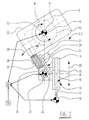
- the rotary cycle cleaning machine has a machine frame 1, which has a total of six processing stations 2.1 - 2.6 for Cleaning and a feed station 3 and a delivery station 4 provides. All stations 2.1 - 2.6, 3 and 4 are even over the circumference of the Distributed machine frame 1.
- a turnstile 6 is provided, which is mounted centrally on the machine frame 1 and can be rotated in cycles via a drive unit 7 indicated in FIG. 1.
- the arms 8.1 to 8.8 of the turnstile 6 have the same division as that Arrangement of the processing stations 2.1 - 2.6 as well as loading and removal stations 3, 4 with respect to the circumference of the machine frame 1, so that by rotating the turnstile 6 by 45 ° each article 5 is transported by one station.
- Suction cups 9 are provided for holding the porcelain plates 5 on the turnstile 6 provided at the free ends of the arms 8.1 - 8.8.
- the station 2.3 in FIG. 2 is representative of the processing stations 2.1-2.6 and shown enlarged. As can be seen from this drawing, is in the processing station 2.3 a mounted on the machine frame 1
- Turntable 10 is provided, which is about a vertical axis with the aid of a servo motor 11 is driven by rotation.
- the turntable 10 is used to hold the each ceramic article to be processed (plate 5). By using it of the servo motor 11, the turntable 10 is in its rotational position controllable in a defined manner with respect to the axis of rotation 12.
- a manipulator unit 13 for the Machining tool provided.
- this has one on one Linear guide 14 horizontally and essentially radially to the center of the Turnstile 6 slidable tool carriage 15 on a usual spindle drive 16 with spindle 17 and spindle nut 18 driven is.
- the spindle 17 is actuated by a further servo motor 19, so that the tool slide 15 defines in the linear direction to the turntable 10th and is therefore deliverable to the ceramic plate 5 to be processed (Infeed direction 20).
- a tool carrier 21 On the tool slide 15 is a tool carrier 21 around a vertical Axis 22 rotatably mounted.
- the rotary drive is operated by another servo motor 23 taken over.
- a boom 24 of the tool carrier 21 On a boom 24 of the tool carrier 21 is a milling tool 25 about a horizontal axis 26 using the motor 27 rotation driven. With the help of the tool carrier 21, this can be done Adjust milling tool 25 in the direction of rotation 28.
- the servomotors 11, 19 and 23 of the turntable 10, spindle drive 16 and Tool carriers 21 are coupled to a common control unit 29, which controls the superimposed movements of these three machine parts.
- the coordinates of the target contour of the ceramic are first Plate 5 determined outside the cleaning machine. Different can do this Procedures are applied, such as. B. mechanical scanning a template or an already finished article. Also the Application of optical image recognition systems, such as vision systems Basis of line or matrix cameras is possible.
- This input unit 30 is only indicated schematically in FIG. 2 as a diagram block.
- the input unit 30 transmits the coordinates of the contour points of the respective ceramic article to the control unit 29, which with a suitable Control program for the contour points and the associated tangent directions determined that the milling tool 25 must take. In doing so the kinematically relevant data stored in the control unit 29 of the individual processing stations 2.1 - 2.6 in the calculation of the Tangent directions included.
- Corresponding travel program for the servomotors 11, 19, 23 is the milling tool depending on the angle of rotation W of the turntable 10 25 by a superimposed movement along the linear guide 14 and about the axis of rotation 22 so that the milling surface 31 - as mentioned - Tangential to the contour 32 of the substantially rectangular plate 5th attacks.
Landscapes
- Engineering & Computer Science (AREA)
- Mechanical Engineering (AREA)
- Structural Engineering (AREA)
- Chemical & Material Sciences (AREA)
- Ceramic Engineering (AREA)
- Manipulator (AREA)
- Devices For Post-Treatments, Processing, Supply, Discharge, And Other Processes (AREA)
Abstract
Description
- Fig. 1
- eine Draufsicht auf eine Rundtakt-Bearbeitungsmaschine, und
- Fig. 2.
- eine vergrößerte Detail-Draufsicht einer Bearbeitungsstation der Rundtakt-Maschine gemäß Fig. 1.
Claims (8)
- Rundtakt-Bearbeitungsmaschine, insbesondere Putzmaschine, für keramische Artikel insbesondere mit komplexen geometrischen Konturformen umfassenddadurch gekennzeichnet, daßein Maschinengestell (1),mehrere, über den Umfang des Maschinengestells (1) verteilte Bearbeitungsstationen (2.1 - 2.6), die jeweils mit Bearbeitungswerkzeugen (25) für den keramischen Artikel (5) bestückt sind,eine Aufgabestation (3) und eine Abnahmestation (4) für die zu bearbeitenden keramischen Artikel (5), undein mehrarmiges Drehkreuz (6) zum Transport der keramischen Artikel (5) zwischen den Stationen (2.1 - 2.6, 3, 4), an dessen Armen (8.1 - 8.8) jeweils Halter (9) für einen keramischen Artikel (5) angeordnet sind,
mindestens eine der Bearbeitungsstationen (2.1 - 2.6) aufweisteinen in seiner Drehstellung definiert steuerbaren Drehteller (10) zur Aufnahme eines keramischen Artikels (5) undeine Manipulatoreinheit (13) für das Bearbeitungswerkzeug (25) mit= einem definiert linear zum Drehteller (10) zustellbaren Werkzeugschlitten (15) und= einem in seiner Drehstellung definiert steuerbaren, drehbar am Werkzeugschlitten (15) gelagerten Werkzeugträger (21) für das Bearbeitungswerkzeug (25). - Bearbeitungsmaschine nach Anspruch 1, dadurch gekennzeichnet, daß der Drehteller (10), der Werkzeugschlitten (15) und der Werkzeugträger (21) jeweils durch Servomotoren (11, 19, 23) angetrieben sind.
- Bearbeitungsmaschine nach Anspruch 1 oder 2, dadurch gekennzeichnet, daß die Zustellrichtung (20) des Werkzeugschlittens (15) horizontal und radial bezüglich dem Drehkreuz (6) weist.
- Bearbeitungsmaschine nach einem der Ansprüche 1 bis 3, dadurch gekennzeichnet, daß die Drehachsen (12, 22) des Drehtellers (10) und des Werkzeugträgers (21) zueinander parallel und vertikal gerichtet sind.
- Bearbeitungsmaschine nach einem der Ansprüche 1 bis 4, dadurch gekennzeichnet, daß eine dem Drehteller (10), dem Werkzeugschlitten (15) und dem Werkzeugträger (21) zugeordnete zentrale Steuereinheit (29) vorgesehen ist, die die sich einander überlagernden Bewegungen von Drehteller (10), Werkzeugschlitten (15) und Werkzeugträger (21) steuert.
- Bearbeitungsmaschine nach Anspruch 5, dadurch gekennzeichnet, daß die Steuereinheit (29) den Drehteller (10), Werkzeugschlitten (15) und Werkzeugträger (21) derart steuert, daß das Bearbeitungswerkzeug (25) die zu bearbeitende Kontur des keramischen Artikels (5) tangential beaufschlagt.
- Bearbeitungsmaschine nach Anspruch 5 oder 6, dadurch gekennzeichnet, daß die Steuereinheit (29) mit einer Eingabeeinheit (30) für die Sollkontur des zu bearbeitenden keramischen Artikels (5) versehen ist.
- Bearbeitungsmaschine nach Anspruch 7, dadurch gekennzeichnet, daß die Eingabeeinheit (30) eine mechanische Schablonen-Abtasteinrichtung oder ein optisch arbeitendes Erkennungssystem für die Artikelkontur ist.
Applications Claiming Priority (2)
| Application Number | Priority Date | Filing Date | Title |
|---|---|---|---|
| DE2000140365 DE10040365C1 (de) | 2000-08-18 | 2000-08-18 | Rundtakt-Bearbeitungsmaschine, insbesondere Putzmaschine, für keramische Artikel |
| DE10040365 | 2000-08-18 |
Publications (2)
| Publication Number | Publication Date |
|---|---|
| EP1184146A2 true EP1184146A2 (de) | 2002-03-06 |
| EP1184146A3 EP1184146A3 (de) | 2003-05-21 |
Family
ID=7652850
Family Applications (1)
| Application Number | Title | Priority Date | Filing Date |
|---|---|---|---|
| EP01115420A Withdrawn EP1184146A3 (de) | 2000-08-18 | 2001-06-27 | Rundtakt-Bearbeitungsmaschine, insbesondere Putzmaschine, für keramische Artikel |
Country Status (2)
| Country | Link |
|---|---|
| EP (1) | EP1184146A3 (de) |
| DE (1) | DE10040365C1 (de) |
Cited By (2)
| Publication number | Priority date | Publication date | Assignee | Title |
|---|---|---|---|---|
| CN104227840A (zh) * | 2014-09-22 | 2014-12-24 | 东莞信柏结构陶瓷有限公司 | 陶瓷制品制备装置及陶瓷制品制备方法 |
| CN108436941A (zh) * | 2018-05-11 | 2018-08-24 | 萍乡学院 | 冰壶机器人 |
Families Citing this family (1)
| Publication number | Priority date | Publication date | Assignee | Title |
|---|---|---|---|---|
| TR201601991A2 (tr) * | 2016-02-16 | 2016-08-22 | Ng Lojistik Pazarlama Yatirim Ve Gayrimenkul Anonim Sirketi | Servo Rütuş Makinası |
Family Cites Families (6)
| Publication number | Priority date | Publication date | Assignee | Title |
|---|---|---|---|---|
| DE2935004A1 (de) * | 1979-08-30 | 1981-03-19 | Fa. Elmetherm, St.-Laurent-sur-Gorre | Putzmaschine fuer keramische formlinge |
| DE3150431A1 (de) * | 1981-12-19 | 1983-07-14 | Maschinen- und Stahlbau Julius Lippert GmbH & Co, 8487 Pressath | Putzmaschine fuer keramisches gut |
| DE3429280C1 (de) * | 1984-08-08 | 1985-11-21 | Gebrüder Netzsch, Maschinenfabrik GmbH & Co, 8672 Selb | Vorrichtung zum Bearbeiten keramischer Gegenstände mit nichtkreisförmigem Rand |
| FR2575100B1 (fr) * | 1984-12-21 | 1989-02-03 | Fonderie Soc Gen De | Machine a surfacer |
| DE4222790C1 (de) * | 1992-07-10 | 1994-01-05 | Netzsch Erich Holding | Verfahren und Anlage zum Entgraten und Weiterbearbeiten von Werkstücken, insbesondere aus keramischem Material |
| GB2278808A (en) * | 1993-06-03 | 1994-12-14 | Central Ceramic Services Limit | Apparatus for treating the edge of an article |
-
2000
- 2000-08-18 DE DE2000140365 patent/DE10040365C1/de not_active Expired - Fee Related
-
2001
- 2001-06-27 EP EP01115420A patent/EP1184146A3/de not_active Withdrawn
Cited By (4)
| Publication number | Priority date | Publication date | Assignee | Title |
|---|---|---|---|---|
| CN104227840A (zh) * | 2014-09-22 | 2014-12-24 | 东莞信柏结构陶瓷有限公司 | 陶瓷制品制备装置及陶瓷制品制备方法 |
| CN104227840B (zh) * | 2014-09-22 | 2016-08-24 | 东莞信柏结构陶瓷股份有限公司 | 陶瓷制品制备装置及陶瓷制品制备方法 |
| CN108436941A (zh) * | 2018-05-11 | 2018-08-24 | 萍乡学院 | 冰壶机器人 |
| CN108436941B (zh) * | 2018-05-11 | 2023-04-11 | 萍乡学院 | 冰壶机器人 |
Also Published As
| Publication number | Publication date |
|---|---|
| EP1184146A3 (de) | 2003-05-21 |
| DE10040365C1 (de) | 2001-11-15 |
Similar Documents
| Publication | Publication Date | Title |
|---|---|---|
| EP2308644B1 (de) | Vorrichtung zur Feinbearbeitung von optisch wirksamen Flächen an Brillengläsern | |
| EP1418019B2 (de) | Werkzeugmaschine mit mindestens zwei Werkzeugrevolvern, die jeweils eine Werkstückgreifvorrichtung aufweisen | |
| DE10026069C2 (de) | CNC-Bearbeitungszentrum sowie Verfahren zur Holzbearbeitung | |
| EP3784432B1 (de) | Werkzeugmaschine mit einer arbeitspindel auf einer schrägfläche | |
| DE202013012320U1 (de) | Honmaschine mit mehreren Arbeitsstationen und Rundtisch | |
| EP3061564B1 (de) | Fräsvorrichtung und verfahren für die brillenglasfertigung mit zwei frässtationen | |
| DE19521846A1 (de) | Numerisch gesteuerte Bearbeitungsmaschine | |
| WO2015110259A2 (de) | Bearbeitungsvorrichtung zur maschinengestützten herstellung und bearbeitung von dentalen werkstücken | |
| DE69109055T2 (de) | Verfahren zum automatischen Bearbeiten der Ränder von Glasscheiben und Gerät zur Durchführung des Verfahrens. | |
| EP0885686B1 (de) | Bearbeitungszelle | |
| DE60219267T2 (de) | Greifeinheit für die automatisierte Bearbeitung von Werkstücken, und Vorrichtung und Verfahren mit einer solchen Einheit | |
| DE19518965A1 (de) | Bearbeitungszentrum und Bearbeitungsverfahren für Holz- und Kunststoff-Werkstoffe | |
| EP3034221A1 (de) | Schleifmaschine mit einem Schleifwerkzeug zum Wälzschleifen zweier Werkstücke | |
| DE10213755A1 (de) | Bearbeitungsmaschine zum mehrachsigen Bewegen eines Werkzeuges oder Werkstückes | |
| EP3291943B1 (de) | Werkzeugmaschine | |
| EP1187700A1 (de) | Positioniervorrichtung für werkstückträger oder werkstücke | |
| DE4237024A1 (de) | Verfahren zum Putzen und Bearbeiten von Gußteilen sowie Putz- und Bearbeitungsanlage für Gußteile | |
| DE10160280B4 (de) | Vorrichtung zur mechanischen Oberflächenbearbeitung von Werkstücken | |
| DE10040365C1 (de) | Rundtakt-Bearbeitungsmaschine, insbesondere Putzmaschine, für keramische Artikel | |
| DE4120781A1 (de) | Verfahren zur bearbeitung der randkontur von vornehmlich unrunden keramischen formteilen sowie vorrichtung zur durchfuehrung des verfahrens | |
| DE202014104881U1 (de) | Schleifmaschine mit einem Schleifwerkzeug zum gleichzeitigen Wälzschleifen zweier Werkstücke | |
| EP1647358A1 (de) | Mehrseitenbearbeitungsmaschine und Positioniervorrichtung für ein Werkstück | |
| EP1604776B1 (de) | Werkzeugmaschine mit Vertikalspindeln | |
| DE202007018833U1 (de) | Werkzeugmaschine | |
| EP4180177B1 (de) | Bearbeitungsvorrichtung für optische werkstücke |
Legal Events
| Date | Code | Title | Description |
|---|---|---|---|
| PUAI | Public reference made under article 153(3) epc to a published international application that has entered the european phase |
Free format text: ORIGINAL CODE: 0009012 |
|
| AK | Designated contracting states |
Kind code of ref document: A2 Designated state(s): AT BE CH CY DE DK ES FI FR GB GR IE IT LI LU MC NL PT SE TR |
|
| AX | Request for extension of the european patent |
Free format text: AL;LT;LV;MK;RO;SI |
|
| RIN1 | Information on inventor provided before grant (corrected) |
Inventor name: FLUEGEL, WERNER Inventor name: MASLOWSKI, JUERGEN |
|
| PUAL | Search report despatched |
Free format text: ORIGINAL CODE: 0009013 |
|
| AK | Designated contracting states |
Designated state(s): AT BE CH CY DE DK ES FI FR GB GR IE IT LI LU MC NL PT SE TR |
|
| AX | Request for extension of the european patent |
Extension state: AL LT LV MK RO SI |
|
| RAP1 | Party data changed (applicant data changed or rights of an application transferred) |
Owner name: SAMA MASCHINENBAU GMBH |
|
| AKX | Designation fees paid | ||
| REG | Reference to a national code |
Ref country code: DE Ref legal event code: 8566 |
|
| STAA | Information on the status of an ep patent application or granted ep patent |
Free format text: STATUS: THE APPLICATION IS DEEMED TO BE WITHDRAWN |
|
| 18D | Application deemed to be withdrawn |
Effective date: 20040402 |