EP1183806B1 - Apparatus and method for gated transmission in cdma communication system - Google Patents
Apparatus and method for gated transmission in cdma communication system Download PDFInfo
- Publication number
- EP1183806B1 EP1183806B1 EP00935679A EP00935679A EP1183806B1 EP 1183806 B1 EP1183806 B1 EP 1183806B1 EP 00935679 A EP00935679 A EP 00935679A EP 00935679 A EP00935679 A EP 00935679A EP 1183806 B1 EP1183806 B1 EP 1183806B1
- Authority
- EP
- European Patent Office
- Prior art keywords
- transmission
- uplink
- dpcch
- downlink
- power control
- Prior art date
- Legal status (The legal status is an assumption and is not a legal conclusion. Google has not performed a legal analysis and makes no representation as to the accuracy of the status listed.)
- Expired - Lifetime
Links
Images


Classifications
-
- H—ELECTRICITY
- H04—ELECTRIC COMMUNICATION TECHNIQUE
- H04W—WIRELESS COMMUNICATION NETWORKS
- H04W52/00—Power management, e.g. TPC [Transmission Power Control], power saving or power classes
- H04W52/04—TPC
- H04W52/06—TPC algorithms
-
- H—ELECTRICITY
- H04—ELECTRIC COMMUNICATION TECHNIQUE
- H04W—WIRELESS COMMUNICATION NETWORKS
- H04W52/00—Power management, e.g. TPC [Transmission Power Control], power saving or power classes
- H04W52/04—TPC
- H04W52/54—Signalisation aspects of the TPC commands, e.g. frame structure
-
- H—ELECTRICITY
- H04—ELECTRIC COMMUNICATION TECHNIQUE
- H04W—WIRELESS COMMUNICATION NETWORKS
- H04W52/00—Power management, e.g. TPC [Transmission Power Control], power saving or power classes
- H04W52/04—TPC
- H04W52/38—TPC being performed in particular situations
- H04W52/44—TPC being performed in particular situations in connection with interruption of transmission
-
- H—ELECTRICITY
- H04—ELECTRIC COMMUNICATION TECHNIQUE
- H04W—WIRELESS COMMUNICATION NETWORKS
- H04W52/00—Power management, e.g. TPC [Transmission Power Control], power saving or power classes
- H04W52/04—TPC
- H04W52/54—Signalisation aspects of the TPC commands, e.g. frame structure
- H04W52/58—Format of the TPC bits
-
- H—ELECTRICITY
- H04—ELECTRIC COMMUNICATION TECHNIQUE
- H04W—WIRELESS COMMUNICATION NETWORKS
- H04W52/00—Power management, e.g. TPC [Transmission Power Control], power saving or power classes
- H04W52/04—TPC
- H04W52/18—TPC being performed according to specific parameters
- H04W52/26—TPC being performed according to specific parameters using transmission rate or quality of service QoS [Quality of Service]
Definitions
- the present invention relates generally to a CDMA mobile communication system, and in particular, to an apparatus and method for gated transmission that assigns channels and does not require a separate resynchronization process.
- a conventional CDMA (Code Division Multiple Access) mobile communication system primarily provides voice services.
- the future CDMA mobile communication system will support the IMT-2000 standard, which provides a high-speed data service as well as the voice service. More specifically, the IMT-2000 standard provides a high-quality voice service, a moving picture service, and an Internet search service.
- a data communication service typically alternates between a transmission of burst data period and a long non-transmission periods.
- the bursts of data are referred to as "packets" or "packages" of data.
- traffic data is transmitted over a dedicated traffic channel for a data transmission duration, and the dedicated traffic channel is maintained for a predetermined time even when a base station and a mobile station have no traffic data to transmit.
- the mobile communication system transmits the traffic data over the dedicated traffic channel for the data transmission duration and maintains the dedicated traffic channel between the base station and the mobile station for a predetermined time even when there is no traffic data to transmit in order to minimize a time delay due to sync reacquisition when there is traffic data to transmit.
- UTRA Universal Mobile Telecommunications System
- Terrestrial Radio Access UMTS (Universal Mobile Telecommunications System) Terrestrial Radio Access) mobile communication system.
- UMTS Universal Mobile Telecommunications System
- Terrestrial Radio Access UMTS (Universal Mobile Telecommunications System) Terrestrial Radio Access) mobile communication system.
- Such a mobile communication system requires many states according to channel assignment circumstances and the existence/nonexistence of state information in order to provide a packet data service as well as a voice service.
- FIG. 1A shows state transition in the cell connected state of the mobile communication system.
- the cell connected state includes a paging channel (PCH) state, a random access channel (RACH)/downlink shared channel (DSCH) state, a RACH/forward link access channel (FACH) state, and a dedicated channel (DCH)/DCH, DCH/DCH+DSCH, DCH/DSCH+DSCH Ctrl (Control Channel) state.
- PCH paging channel
- RACH random access channel
- DSCH downlink shared channel
- FACH forward link access channel
- DCH dedicated channel
- DCH dedicated channel
- FIG. 1B shows a user data active substate and a control-only substate of the DCH/DCH, DCH/DCH+DSCH, DCH/DSCH+DSCH Ctrl state. It should be noted that the novel gated transmission device and method is applied to a state where there is no traffic data to transmit for a predetermined time (e.g., DCH/DCH control-only substate).
- the existing CDMA mobile communication system which mainly provides the voice service releases a channel after completion of data transmission and connects the channel again when there is further data to transmit.
- the conventional data transmission method has many delaying factors such as a reconnection delay, thus making it difficult to provide a high-quality service. Therefore, to provide the packet data service as well as the voice service, an improved data transmission method is required. For example, in many cases, data transmission is performed intermittently for Internet access and file downloading. Thus, there are transmission and non-transmission periods. During the non-transmission period, the conventional data transmission method releases or maintains the traffic (or data) channel(DPDCH OR DSCH) and associated control channel(DPCCH). Releasing the traffic channel and associated control channel require a long time to reconnect the channels, and maintaining the traffic channel and associated control channel waste the channel resources.
- a downlink (or forward link) for transmitting signals from the base station to the mobile station or an uplink (or reverse link) for transmitting signals from the mobile station to the base station includes the following physical channels.
- the physical channels include a dedicated physical control channel (hereinafter, referred to as DPCCH) in which pilot symbols are included for sync acquisition and channel estimation, and a dedicated physical data channel (hereinafter, referred to as DPDCH) for exchanging traffic data with a specific mobile station.
- DPCCH dedicated physical control channel
- DPDCH dedicated physical data channel
- the downlink DPDCH includes the traffic data
- the downlink DPCCH includes, at each slot (or power control group), transport format combination indicator (hereinafter, referred to as TFCI) which is information about the format of transmission data, transmit power control (hereinafter, referred to as TPC) information which is a power control command, and control information such as the pilot symbols for providing a reference phase so that a receiver (the base station or the mobile station) can compensate the phase.
- TFCI transport format combination indicator
- TPC transmit power control
- control information such as the pilot symbols for providing a reference phase so that a receiver (the base station or the mobile station) can compensate the phase.
- the DPDCH and the DPCCH are time multiplexed within one power control group and the DPDCH and DPCCH signals are spread with one orthogonal code in downlink, and DPDCH and DPCCH signals are separated by using different orthogonal codes in the uplink.
- each frame length is 10msec and each frame includes 16 or 15 power control groups (PCGs), i.e., each power control group has a length of 0.625msec or 0.667msec. It will be assumed herein that the power control group (0.625msec or 0.667 ms) has the same time period as the slot (0.625msec or 0.667 ms).
- the power control group (or slot) is comprised of pilot symbol, traffic data, transmission data format concerning information TFCI, and power control information TPC. The values stated above are given by way of example only.
- FIG. 2A shows a slot structure including the downlink DPDCH and DPCCH.
- the DPDCH is divided into traffic data 1 and traffic data 2
- traffic data 1 does not exist and only the traffic data 2 exists according to the types of the traffic data.
- Table 1 shows the symbols constituting the downlink DPDCH/DPCCH fields, wherein the number of TFCI, TPC and pilot bits in each slot can vary according to a data rate and a spreading factor.
- uplink DPDCH and DPCCH for transmitting signals from the mobile station to the base station are separated by channel separation codes.
- FIG. 2B shows a slot structure including the uplink DPDCH and DPCCH.
- the number of TFCI, FBI (FeedBack Information), TPC and pilot bits can vary according to the circumstances influencing the type of the traffic data, such as a provided service, transmit antenna diversity, or a handover (or handoff).
- the FBI is information about two antennas that the mobile station requests, when the base station uses transmit diversity antennas. Tables 2 and 3 below show the symbols constituting the uplink DPDCH and DPCCH fields, respectively.
- Tables 1 to 3 show an example where one DPDCH is a traffic channel. However, there may exist second, third and fourth DPDCHs according to the service types. Further, the downlink and uplink both may include several DPDCHs.
- SF indicates a Spreading Factor.
- a hardware structure of the conventional mobile communication system (base station transmitter and mobile station transmitter) will be described below with reference to FIGS. 3A and 3B .
- the base station transmitter and mobile station transmitter will be described with reference to three DPDCHs, the number of DPDCHs is not limited.
- FIG. 3A shows a structure of the conventional base station transmitter.
- multiplier 111 multiply a DPCCH signal by gain coefficient G1
- multipliers 121, 131 and 132 multiply DPDCH 1 , DPDCH 2 and DPDCH 3 signals, which have undergone channel encoding and interleaving, by gain coefficients G 2 , G 3 and G 4 , respectively.
- the gain coefficients G 1 , G 2 , G 3 and G 4 may have different values according to circumstances such as the service option and the handover.
- a multiplexer (MUX) 112 time-multiplexes the DPCCH signal and the DPDCH 1 signal into the slot structure of FIG. 2A .
- MUX multiplexer
- a first serial-to-parallel (S/P) converter 113 distributes the output of the multiplexer 112 to an I channel and a Q channel.
- Second and third S/P converters 133 and 134 S/P-convert the DPDCH 2 and DPDCH 3 signals and distribute them to the I channel and the Q channel, respectively.
- the S/P converted I and Q channel signals are multiplied by channelization codes C ch1 , C ch2 and E ch3 in multipliers 114, 122, 135, 136, 137 and 138, for spreading and channel separation. Orthogonal codes are used for the channelization codes.
- the I and Q channel signals multiplied by the channelization codes in the multipliers 114, 122, 135, 136, 137 and 138 are summed by first and second summers 115 and 123, respectively. That is, the I channel signals are summed by the first summer 115, and the Q channel signals are summed by the second summer 123.
- the output of the second summer 123 is phase shifted by 90° by a phase shifter 124.
- a summer 116 sums an output of the first summer 115 and an output of the phase shifter 124 to generate a complex signal I+jQ.
- a multiplier 117 scrambles the complex signal with a PN sequence C scramb which is uniquely assigned to each base station, and a signal separator 118 separates the scrambled signal into a real part and an imaginary part and distributes them to the I channel and the Q channel.
- the I and Q channel outputs of the signal separator 118 are filtered by lowpass filters 119 and 125, respectively, to generate bandwidth-limited signals.
- the output signals of the filters 119 and 125 are multiplied by carriers cos ⁇ 2 ⁇ f c t ⁇ and sin ⁇ 2 ⁇ f c t ⁇ in multipliers 120 and 126, respectively, to frequency shift the signals to a radio frequency (RF) band.
- RF radio frequency
- FIG. 3B shows a structure of the conventional mobile station transmitter.
- multipliers 211, 221, 223 and 225 multiply a DPCCH signal and DPDCH 1 , DPDCH 2 and DPDCH 3 signals, which have undergone channel encoding and interleaving, by channelization codes C ch1 , C ch2 , C ch3 and C ch4 , respectively, for spreading and channel separation.
- Orthogonal codes are used for the channelization codes.
- the output signals of the multipliers 211, 221, 223 and 225 are multiplied by gain coefficients G 1 , G 2 , G 3 and G 4 in multipliers 212, 222, 224 and 226, respectively.
- the gain coefficients G 1 , G 2 , G 3 and G 4 may have different values.
- the outputs of the multipliers 212 and 222 are summed by a first summer 213 and output as an I channel signal, and the outputs of the multipliers 224 and 226 are summed by a second summer 227 and output as a Q channel signal.
- the Q channel signal output from the second summer 227 is phase shifted by 90° in a phase shifter 228.
- a summer 214 sums the output of the first summer 213 and the output of the phase shifter 228 to generate a complex signal I+jQ.
- a multiplier 215 scrambles the complex signal with a PN sequence C scramb which is uniquely assigned to each base station, and a signal separator 229 separates the scrambled signal into a real part and an imaginary part and distributes them to the I channel and the Q channel.
- the I and Q channel outputs of the signal separator 229 are filtered by lowpass filters 216 and 230, respectively, to generate bandwidth-limited signals.
- the output signals of the filters 216 and 230 are multiplied by carriers cos ⁇ 2 ⁇ f c t ⁇ and sin ⁇ 2 ⁇ f c t ⁇ in multipliers 217 and 231, respectively, to frequency shift the signals to a radio frequency (RF) band.
- RF radio frequency
- FIG. 5A shows how to transmit the downlink DPCCH and the uplink DPCCH when transmission of the uplink DPDCH is discontinued in a state where there is no data to transmit for a predetermined time.
- FIG. 5B shows how to transmit the downlink DPCCH and the uplink DPCCH when transmission of the downlink DPDCH is discontinued in a state where there is no data to transmit for a predetermined time.
- the mobile station constantly transmits the uplink DPCCH signal even when the DPDCH data is not existing in order to avoid a resync acquisition process in the base station.
- the base station and the mobile station make a transition to an RRC (Radio Resource Control) connection release state (not shown).
- RRC Radio Resource Control
- a method for transmitting a frame comprised of a plurality of slots over a dedicated control channel in a duration where there is no transmission message from a mobile station to a base station Each slot in the frame is comprised of a first slot duration and a second slot duration.
- the first slot duration is provided with a power control signal and the second slot duration is provided with no signal at a partial duration thereof.
- normal transmission refers to continuously transmitting DPCCH signal, control information included in the downlink DPCCH, i.e., TFCI, TPC and pilot symbols or control information included in the uplink DPCCH, ie., TFCI, TPC, FBI and pilot symbols
- gate transmission refers to transmitting the control information included in the downlink DPCCH (i.e., TFCI, TPC and pilot symbols) only at a specific power control group (or slot) according to a predetermined time pattern.
- gate transmission refers to transmitting the control information included in the uplink DPCCH (i.e., TFCI, TPC, FBI and pilot symbols) only at a specific power control group (or slot) according to a predetermined time pattern.
- the information, transmission of which is discontinued in the downlink DPCCH during gated transmission may include all of the TFCI, TPC and pilot symbols in an nth power control group (or one slot), or may include the pilot symbols in an nth power control group (or one slot), and TFCI and TPC in an (n+1)th power control group.
- the information, transmission of which is discontinued in the uplink DPCCH during gated transmission includes all of TFCI, TPC, FBI and pilot symbols in a specific power control group (or one slot).
- a gated transmission unit is identical to a slot unit
- TFCI, TPC and pilot symbols within one power control group are set as a gated transmission unit in uplink.
- a gated transmission unit is not identical to a slot unit” means that an nth pilot symbol and (n+1)th TFCI and TPC are set as a gated transmission unit in downlink.
- the invention locates the TPC for controlling power of the first slot of the next frame at the last slot of one frame. That is, TPC bits for the downlink DPCCH and the uplink DPCCH are located at the last slot of the nth frame, and power of the first slot of the (n+1)th frame is controlled using the TPC bits existing at the last slot of the nth frame.
- a power control rate can be maintained even when transmission data is generated during gated transmission of the control information according to the present invention. That is, gating of power control information (TPC) is maintained even when transmission data is generated during gated transmission of the control information.
- a gating pattern (or gated transmission pattern) for the downlink DPCCH and a gating pattern for the uplink DPCCH are determined to have an offset. That is, the control information for the downlink DPCCH and the control information for the uplink DPCCH are transmitted at different time points.
- FIG. 4A shows a structure of a base station transmitter according to an embodiment of the present invention.
- the base station transmitter is different from the conventional one of FIG. 3A in that with regard to the downlink DPCCH, the output of the multiplier 111 is gated by a gated transmission controller 141. That is, the gated transmission controller 141 performs gated transmission on the TFCI and TPC bits for the downlink DPCCH at a power control group (or time slot) scheduled with the mobile station in a state where the traffic data is not transmitted over the downlink and uplink DPDCHs for a predetermined period of time.
- the gated transmission controller 141 performs gated transmission on one power control group (or one entire slot) including the pilot symbols, TFCI and TPC bits for the downlink DPCCH at a power control group (or time slot) scheduled with the mobile station in a state where the traffic data is not transmitted over the downlink and uplink DPDCHs for a predetermined period of time.
- the downlink gated transmission pattern is identical to the uplink gated transmission pattern, an offset may exist between them for efficient power control.
- the offset is given as a system parameter.
- the gated transmission controller 141 can perform gated transmission either when the gated transmission unit is identical to the slot unit or when the gated transmission unit is not identical to the slot unit.
- the gated transmission controller 141 separately gates the TFCI, TPC and pilot symbols. That is, nth pilot symbol, (n+1)th TFCI and TPC are set as a gated transmission unit.
- the gated transmission controller 141 locates the TPC bits for power controlling the first slot of the next frame at the last slot of one frame to secure performance on a beginning part of the next frame. That is, the TPC bits for the downlink DPCCH and the uplink DPCCH are located at the last slot of the nth frame, and power of the first slot of the (n+1)th frame is controlled using the TPC bits existing at the last slot of the nth frame.
- FIG. 4B shows a structure of a mobile station transmitter according to an embodiment of the present invention.
- the mobile station transmitter is different from the conventional one of FIG. 3B in that a gated transmission controller 241 is provided to gate transmission of the uplink DPCCH. That is, the gated transmission controller 241 performs gated transmission on one power control group (or one entire slot) or 1/2 the power control group including the pilot symbols, TFCI, FBI and TPC bits for the uplink DPCCH at a power control group (or time slot) scheduled with the mobile station in the control-only substate where the traffic data is not transmitted over the downlink and uplink DPDCHs.
- a gated transmission controller 241 performs gated transmission on one power control group (or one entire slot) or 1/2 the power control group including the pilot symbols, TFCI, FBI and TPC bits for the uplink DPCCH at a power control group (or time slot) scheduled with the mobile station in the control-only substate where the traffic data is not transmitted over the downlink and uplink DPDCHs.
- FIG. 6A shows a method for transmitting a signal according to a regular or gated transmission pattern for the uplink DPCCH when there is no DPDCH data to transmit for a predetermined period of time, according to an embodiment of the present invention.
- reference numerals 301, 302, 303 and 304 show different gating rates according to a ratio of a duty cycle (hereinafter, referred to as DC).
- the gating rate transition method can be divided into several methods as stated below, and is determined according to system setup.
- FIG. 6B shows a method for transmitting a signal according to a regular or gated transmission pattern for the uplink DPCCH when there is no DPDCH data to transmit for a predetermined time, according to another embodiment of the present invention.
- reference numerals 305, 306 and 307 show different gating rates according to a ratio of a duty cycle DC.
- the above gating rate transition method can be divided into several methods as stated below, and is determined according to system setup.
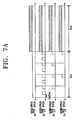
- FIGS. 7A and 7B show the uplink DPCCH for the case where a transition message is transmitted over the uplink DPDCH when a dedicated MAC (Medium Access Control) logical channel is generated when there is no DPDCH data for a predetermined time as in FIGS. 6A and 6B .
- the TPC bits for downlink power control can be omitted and the pilot duration (or period) can be extended to a power control group length.
- the power control groups which were transmitted according to the gated transmission pattern, undergo normal transmission to transmit the downlink DPDCH message.
- the TPC bits for downlink power control can be omitted and the pilot duration can be extended to a power control group length.
- the power control groups represented by reference numerals 315, 316 and 317 are transmitted according to the gated transmission patterns, and undergo normal transmission to transmit the uplink DPDCH message.
- the TPC bits for downlink power control can be omitted and the pilot duration (or period) can be extended to a power control group length. Beginning at the power control groups succeeding after transmitting the uplink DPDCH message by normal transmission of the power control groups, it is possible to transmit the uplink DPCCH without gating, or it is possible to gate transmission of the uplink DPCCH according to the original DC value until a state transition message is received from the base station.
- FIG. 8A shows a method for transmitting downlink and uplink signals when transmission of a downlink DPDCH is discontinued.
- the base station and the mobile station start gated transmission if a set timer value expires or a downlink DPDCH message for state transition is generated.
- FIG. 8A shows an embodiment where a message for starting gated transmission is generated by the base station, it is also possible for the mobile station to send a gating request message to the base station when there is no downlink and uplink DPDCH. While transmitting the downlink DPCCH in FIG.
- the mobile station ignores the meaningless TPC values transmitted from the base station in order to perform uplink power control in consideration of the gating pattern for the uplink DPCCH, and performs transmission at the same transmission power as the transmission power for the previous power control group.
- the downlink DPCCH in FIG. 8A it is also possible to gate only the TFCI and TPC bits in the downlink DPCCH without gating the pilot symbols in the downlink DPCCH.
- the gating pattern is identical to a gating pattern for the uplink DPCCH of the mobile station.
- the power control group in which the TPC bits in the downlink DPCCH are gated, refers to the TPC bits generated by measuring the pilot symbols corresponding to the gated power control group in the DPCCH transmitted from the mobile station.
- Reference numeral 802 shows a situation where a message generated for gated transmission is transmitted to the mobile station over the downlink DPDCH.
- FIG. 8B shows a method for transmitting downlink and uplink signals when transmission of an uplink DPDCH is discontinued.
- the base station and the mobile station perform gated transmission at a time point appointed (or scheduled) between them when a set timer value expires or after exchanging a state transition message.
- FIG. 8B shows an embodiment where the message for gated transmission is generated in the downlink DPDCH, the gated transmission message can also be generated in the uplink DPDCH of the mobile station. While transmitting the downlink DPCCH in FIG. 8B , it is also possible to transmit all the TFCI, TPC and pilot symbols without gating.
- the mobile station Since the TPC bits include meaningless TPC values determined by measuring power strength of the pilot symbols of the gated power control groups within the uplink DPCCH, the mobile station ignores the meaningless TPC values transmitted from the base station in order to perform uplink power control in consideration of the gating pattern for the uplink DPCCH, and performs transmission at the same transmission power as the transmission power for the previous power control group.
- the downlink DPCCH in FIG. 8B it is also possible to gate only the TFCI and TPC bits in the downlink DPCCH without gating the pilot symbols in the downlink DPCCH.
- the gating pattern is identical to a gating pattern for the uplink DPCCH of the mobile station.
- the power control group, in which the TPC bits in the downlink DPCCH are gated refers to the TPC bits generated by measuring the pilot symbols corresponding to the gated power control group in the DPCCH transmitted from the mobile station.
- Reference numeral 804 shows a situation where a gated transmission message generated by the base station is transmitted to the mobile station over the downlink DPDCH.
- FIG. 8C shows a method for transmitting downlink and uplink signals when transmission of a downlink DPDCH is discontinued.
- the base station and the mobile station start gated transmission if a set timer value expires or a downlink DPDCH message for starting gated transmission is generated.
- FIG. 8C shows an embodiment where the message for gated transmission is generated by the base station, it is also possible for the mobile station to send a gated transmission request message to the base station when there is no downlink and uplink DPDCH. While transmitting the downlink DPCCH in FIG.
- the mobile station ignores the meaningless TPC values transmitted from the base station in order to perform uplink power control in consideration of the gating pattern for the uplink DPCCH, and performs transmission at the same transmission power as the transmission power for the previous power control group.
- the downlink DPCCH in FIG. 8C it is also possible to gate only the TFCI and TPC bits in the downlink DPCCH without gating the pilot symbols in the downlink DPCCH.
- the gating pattern is identical to a gating pattern for the uplink DPCCH of the mobile station.
- the power control group in which the TPC bits in the downlink DPCCH are gated, refers to the TPC bits generated by measuring the pilot symbols corresponding to the gated power control group in the DPCCH transmitted from the mobile station.
- Reference numeral 806 shows a situation where a gated transmission message generated by the mobile station is transmitted to the base station over the uplink DPDCH.
- FIG. 8D shows a method for transmitting downlink and uplink signals when transmission of an uplink DPDCH is discontinued.
- the base station and the mobile station can start gated transmission at a time point appointed (or scheduled) between them when a set timer value expires or after exchanging a gated transmission message.
- FIG. 8D shows an embodiment where the message for gated transmission is generated in the downlink DPDCH, the gated transmission message can also be generated in the uplink DPDCH of the mobile station. While transmitting the downlink DPCCH in FIG.
- the mobile station ignores the meaningless TPC values transmitted from the base station in order to perform uplink power control in consideration of the gating pattern for the uplink DPCCH, and performs transmission at the same transmission power as the transmission power for the previous power control group.
- the downlink DPCCH in FIG. 8D it is also possible to gate only the TFCI and TPC bits in the downlink DPCCH without gating the pilot symbols in the downlink DPCCH.
- the gating pattern is identical to a gating pattern for the uplink DPCCH of the mobile station.
- the power control group in which the TPC bits in the downlink DPCCH are gated, refers to the TPC bits generated by measuring the pilot symbols corresponding to the gated power control group in the DPCCH transmitted from the mobile station.
- Reference numeral 808 shows a situation where a gated transmission message generated by the mobile station is transmitted to the base station over the uplink DPDCH.
- FIG. 9A shows a method for transmitting downlink and uplink signals when transmission of a downlink DPDCH is discontinued.
- the base station and the mobile station can start gated transmission at a time point appointed between them if a set timer value expires or after exchanging a gated transmission message.
- FIG. 9A shows a case where a gating pattern for the downlink DPCCH is identical to a gating pattern for the uplink DPCCH.
- FIG. 9A shows an embodiment where the gated transmission message is generated through the downlink DPDCH, the gated transmission message can also be generated through the uplink DPDCH of the mobile station.
- FIG. 9B shows a method for transmitting downlink and uplink signals when transmission of an uplink DPDCH is discontinued.
- the base station and the mobile station can start gated transmission at a time point appointed between them if a set timer value expires or after exchanging a gated transmission message.
- FIG. 9B shows a case where a gating pattern for the downlink DPCCH is identical to a gating pattern for the uplink DPCCH.
- FIG. 9B shows an embodiment where the gated transmission message is generated through the downlink DPDCH, the gated transmission message can also be generated through the uplink DPDCH of the mobile station.
- the downlink and uplink frames have the same frame start point.
- FIGS. 10A and 10B show structures of the base station controller and the mobile station controller, which enable such gated transmission, respectively.
- FIG. 10A shows gated transmission for the downlink and uplink DPCCHs according to a first embodiment of the present invention.
- a gated transmission unit for the downlink DPCCH may not be a slot unit. That is, with regard to two adjacent slots, a pilot symbol of an nth slot and TFCI and TPC bits of an (n+1)th slot are set as a gated transmission unit for the downlink DPCCH. This is because the pilot symbol is used to estimate a channel by detecting TFCI and TPC. For example, when a gating rate is 1/2, a pilot symbol of a slot number 0 and TFCI and TPC bits of a slot number 1 are set as a gated transmission unit for the downlink DPCCH.
- a pilot symbol of a slot number 2 and TFCI and TPC bits of a slot number 3 are set as a gated transmission unit for the downlink DPCCH.
- a pilot symbol of a slot number 6 and TFCI and TPC bits of a slot number 7 are set as a gated transmission unit for the downlink DPCCH.
- the gated transmission unit for the downlink DPCCH is set to be different from the actual slot unit, since an nth pilot symbol may be required in the receiver to demodulate the (n+1)th TPC according to a demodulation method for the TPC signal.
- TPC for the downlink DPCCH and TPC for the uplink DPCCH are located at a slot number 15 (i.e., 16 th slot which is the last slot of one frame), so that the first slot of an (n+1)th frame should be power controlled using the TPC bits existing in the last slot of an nth frame. That is, TPC for power controlling the first slot of the next frame is located at the last slot of the present frame.
- an offset between the downlink and uplink frame start points is fixed to 250 ⁇ sec.
- the offset value can be changed to an arbitrary value while the base station and the mobile station exchange a parameter for DPCCH gated transmission in the call setup process.
- the offset value is set to a proper value in consideration of a propagation delay of the base station and the mobile station in the call setup process. That is, when the cell radius is over 30Km, the offset value can be set to a value larger than the conventional offset value of 250 ⁇ sec for DPCCH gated transmission, and the value can be determined through experiments.
- FIG. 10B shows gated transmission for the downlink and uplink DPCCHs according to a second embodiment of the present invention.
- FIG. 10B shows a case where transmission of the downlink DPCCH goes ahead of transmission of the uplink DPCCH during gated transmission, for the gating rates of 1/2, 1/4 and 1/8.
- the difference i.e., offset
- DL-UD timing for the gating rates of 1/2, 1/4 and 1/8.
- a pilot symbol of the nth slot and TFCI and TPC of the (n+1)th slot are set as a gated transmission unit for the downlink DPCCH.
- a pilot symbol of a slot number 0 and TFCI and TPC of a slot number 1 are set as a gated transmission unit for the downlink DPCCH.
- a pilot symbol of a slot number 2 and TFCI and TPC of a slot number 3 are set as a gated transmission unit for the downlink DPCCH.
- a pilot symbol of a slot number 6 and TFCI and TPC of a slot number 7 are set as a gated transmission unit for the downlink DPCCH.
- TPC for power controlling the first slot of the next frame is located at the last slot of the present frame. That is, TPC for the downlink DPCCH and TPC for the uplink DPCCH are both located at a slot number 15 (i.e., 16 th slot).
- FIG. 10C shows gated transmission for the downlink and uplink DPCCHs according to a third embodiment of the present invention.
- FIG. 10C shows a case where transmission of the uplink DPCCH goes ahead of transmission of the downlink DPCCH during gated transmission, for the gating rates of 1/2, 1/4 and 1/8.
- a pilot symbol of the nth slot and TFCI and TPC of the (n+1)th slot are set as a gated transmission unit for the downlink DPCCH.
- a pilot symbol of a slot number 1 and TFCI and TPC of a slot number 2 are set as a gated transmission unit for the downlink DPCCH.
- a pilot symbol of a slot number 2 and TFCI and TPC of a slot number 3 are set as a gated transmission unit for the downlink DPCCH.
- a pilot symbol of a slot number 6 and TFCI and TPC of a slot number 7 are set as a gated transmission unit for the downlink DPCCH.
- TPC for power controlling the first slot of the next frame is located at the last slot of the present frame. That is, TPC for the downlink DPCCH and TPC for the uplink DPCCH are both located at a slot number 15 (i.e., 16 th slot).
- FIG. 10D shows gated transmission for the downlink and uplink DPCCHs according to a fourth embodiment of the present invention.
- FIG. 10D shows a case where for the gating rates of 1/2, 1/4 and 1/8, transmission of the downlink DPCCH goes ahead of transmission of the uplink DPCCH during gated transmission, and the downlink and uplink gating patterns are set to the same period.
- a pilot symbol of the nth slot and TFCI and TPC of the (n+1)th slot are set as a gated transmission unit for the downlink DPCCH.
- a pilot symbol of a slot number 0 and TFCI and TPC of a slot number 1 are set as a gated transmission unit for the downlink DPCCH.
- a pilot symbol of a slot number 0 and TFCI and TPC of a slot number 1 are set as a gated transmission unit for the downlink DPCCH.
- a pilot symbol of a slot number 2 and TFCI and TPC of a slot number 3 are set as a gated transmission unit for the downlink DPCCH.
- TPC for power controlling the first slot of the next frame is located at the last slot of the present frame. That is, TPC for the downlink DPCCH and TPC for the uplink DPCCH are both located at a slot number 15 (i.e., 16 th slot).
- FIG. 10E shows gated transmission for the downlink and uplink DPCCHs according to a fifth embodiment of the present invention.
- FIG. 10E shows a case where for the gating rates of 1/2, 1/4 and 1/8, transmission of the uplink DPCCH goes ahead of transmission of the downlink DPCCH during gated transmission, and the downlink and uplink gating patterns are set to the same period.
- a pilot symbol of the nth slot and TFCI and TPC of the (n+1)th slot are set as a gated transmission unit for the downlink DPCCH.
- a pilot symbol of a slot number 1 and TFCI and TPC of a slot number 2 are set as a gated transmission unit for the downlink DPCCH.
- a pilot symbol of a slot number 2 and TFCI and TPC of a slot number 3 are set as a gated transmission unit for the downlink DPCCH.
- a pilot symbol of a slot number 6 and TFCI and TPC of a slot number 7 are set as a gated transmission unit for the downlink DPCCH.
- TPC for power controlling the first slot of the next frame is located at the last slot of the present frame. That is, TPC for the downlink DPCCH and TPC for the uplink DPCCH are both located at a slot number 15 (i.e., 16 th slot).
- FIG. 10E shows that TPC for the downlink DPCCH is not located at the slot number 15 for a 1/2 gating rate.
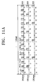
- FIG. 11A shows a method for transmitting a signal according to regular or gated transmission pattern for an uplink DPCCH in a gating mode according to an embodiment of the present invention.
- gated transmission can be performed in a unit of a partial power control group (PCG) duration (e.g., 1/2 PCG) rather than in a unit of one PCG.
- PCG partial power control group
- the embodiment will have the same operation as described above, except that gated transmission is performed in the unit of 1/2 PCG.
- Performing gate transmission in the unit of 1/2 PCG is to increase a rate of downlink power control and decrease the influence of delay.
- gated transmission is performed in the order of the second half of the 1 st slot, the second half of the 3 rd slot, the second half of the 5 th slot, ..., the second half of 15 th slot.
- gated transmission is performed in the order of the second half of the 3 rd slot, the second half of the 7 th slot, the second half of the 11 th slot, ..., the second half of 15 th slot.
- the slot positions where transmission occurs may be varied.
- a mobile station transmitter for gating transmission of the uplink DPCCH in the unit of 1/2 PCG as shown in FIG. 11A has the same structure as the mobile station transmitter shown in FIG. 4B .
- the gated transmission controller 241 has different operation. That is, the gated transmission controller 241 which performs gated transmission in the unit of 1/2 PCG, gates transmission of 1/2 PCG including the pilot symbol and the TFCI, FBI and TPC bits at a predetermined 1/2 PCG position.
- the mobile station of FIG. 4B transmits a frame comprised of a plurality of slots to the base station over the uplink DPCCH at a duration where there is no transmission message.
- each slot in the frame is divided into a first slot duration and a second slot duration, and the gated transmission controller 241 provides a power control signal to the first slot duration and provides no signal to a part of the second slot duration.
- FIG. 11B shows a PCG structure of the DPCCH used when the uplink DPCCH is gated in the unit of 1/2 PCG.
- the second half of the PCG is comprised of the pilot, TFCI; FBI and TPC symbols.
- Tables 4A, 4B and 4C below show the symbols constituting an uplink DPCCH field.
- N pilot , N TPC , N TFCI and N FBI indicate the number of the pilot, TPC, TPCI and FBI bits included in each slot, respectively.
- the bit number of each field may be either fixed to a predetermined value, or indicated by a message provided from the base station. It is also possible to determine the number of fields for gated transmission in a similar manner, even for a case other than those shown in Tables 4A, 4B and 4
- FIG. 11C shows an uplink DPCCH message transmitted when a message to be transmitted over the uplink DPDCH is generated in a gating mode in the unit of 1/2 PCG according to an embodiment of the present invention.
- the gated portion of the uplink DPCCH is filled with the pilot symbol before transmission. Transmission of the TFCI, FBI, TPC fields is optional.
- the invention minimizes the time required for the sync reacquisition process in the base station, minimizes an increase in interference and a decrease in the mobile station using time due to continuous transmission of the uplink DPCCH, and minimizes an increase in interference due to transmission of the uplink power control bit over the downlink, thereby to increase the capacity.
Landscapes
- Engineering & Computer Science (AREA)
- Computer Networks & Wireless Communication (AREA)
- Signal Processing (AREA)
- Mobile Radio Communication Systems (AREA)
Applications Claiming Priority (3)
| Application Number | Priority Date | Filing Date | Title |
|---|---|---|---|
| KR9919647 | 1999-05-29 | ||
| KR10-1999-0019647A KR100492968B1 (ko) | 1999-05-29 | 1999-05-29 | 부호분할다중접속 통신시스템의 제어유지 부상태에서의 단속적채널 송신 장치 및 방법 |
| PCT/KR2000/000555 WO2000074291A1 (en) | 1999-05-29 | 2000-05-29 | Apparatus and method for gated transmission in cdma communication system |
Publications (3)
| Publication Number | Publication Date |
|---|---|
| EP1183806A1 EP1183806A1 (en) | 2002-03-06 |
| EP1183806A4 EP1183806A4 (en) | 2005-07-20 |
| EP1183806B1 true EP1183806B1 (en) | 2008-02-13 |
Family
ID=19588633
Family Applications (1)
| Application Number | Title | Priority Date | Filing Date |
|---|---|---|---|
| EP00935679A Expired - Lifetime EP1183806B1 (en) | 1999-05-29 | 2000-05-29 | Apparatus and method for gated transmission in cdma communication system |
Country Status (9)
| Country | Link |
|---|---|
| US (1) | US7085254B1 (zh) |
| EP (1) | EP1183806B1 (zh) |
| KR (1) | KR100492968B1 (zh) |
| CN (1) | CN1258272C (zh) |
| AU (1) | AU766485B2 (zh) |
| BR (1) | BR0011054A (zh) |
| CA (1) | CA2377355C (zh) |
| DE (1) | DE60038021T2 (zh) |
| WO (1) | WO2000074291A1 (zh) |
Families Citing this family (22)
| Publication number | Priority date | Publication date | Assignee | Title |
|---|---|---|---|---|
| KR20040008230A (ko) * | 2001-06-27 | 2004-01-28 | 노오텔 네트웍스 리미티드 | 무선 통신 시스템에서 제어 정보의 통신 |
| US6983166B2 (en) * | 2001-08-20 | 2006-01-03 | Qualcomm, Incorporated | Power control for a channel with multiple formats in a communication system |
| KR100857788B1 (ko) * | 2002-02-05 | 2008-09-09 | 엘지전자 주식회사 | 패킷 데이터 시스템에서 컨트롤 홀드 모드에서 액티브모드로 변환 방법 |
| JP3594086B2 (ja) * | 2002-02-08 | 2004-11-24 | ソニー株式会社 | 移動体通信における情報多重方法、伝送フォーマット組合せ識別子のデコード方法および装置、移動局装置、基地局装置および移動体通信システム |
| DE10306170A1 (de) * | 2003-02-13 | 2004-09-02 | Siemens Ag | Verfahren zum Einstellen der Sendeleistungen zweier Kanäle einer Verbindung, Station und Kommunikationssystem |
| US20050009523A1 (en) * | 2003-07-07 | 2005-01-13 | Nokia Corporation | Protocol using forward error correction to improve handover |
| US20050068921A1 (en) * | 2003-09-29 | 2005-03-31 | Jung-Tao Liu | Multiplexing of physical channels on the uplink |
| US8565684B2 (en) * | 2003-10-14 | 2013-10-22 | Motorola Mobility Llc | Method and apparatus for controlling reverse link transmission |
| US7106714B2 (en) * | 2003-11-25 | 2006-09-12 | Motorola, Inc. | Method and apparatus for transmission of control data in a packet data communication system |
| US8965440B2 (en) * | 2005-05-31 | 2015-02-24 | Alcatel Lucent | Method of estimating a current channel condition in a wireless communications network |
| US7809395B2 (en) | 2006-02-15 | 2010-10-05 | Broadcom Corporation | Method and system for controlling transmit circuitry in a wide band CDMA network |
| US7907961B2 (en) | 2006-06-07 | 2011-03-15 | Broadcom Corporation | Method and apparatus for improving noise power estimate in a WCDMA network |
| US8731593B2 (en) * | 2006-02-15 | 2014-05-20 | Broadcom Corporation | Method and apparatus for processing transmit power control (TPC) commands in a wideband CDMA (WCDMA) network |
| US8565195B2 (en) * | 2006-08-21 | 2013-10-22 | Nokia Corporation | Apparatus, methods and computer program products providing support for packet data user continuous uplink connectivity |
| WO2008024357A2 (en) * | 2006-08-24 | 2008-02-28 | Interdigital Technology Corporation | Power control for improving link reliability in hsdpa |
| US8503403B2 (en) | 2006-12-21 | 2013-08-06 | Sony Corporation | Network control of uplink transmit timing for compressed mode |
| US7715865B2 (en) | 2006-12-21 | 2010-05-11 | Sony Ericsson Mobile Communications Ab | Compressed mode for reducing power consumption |
| WO2009044458A1 (ja) * | 2007-10-02 | 2009-04-09 | Fujitsu Limited | ハンドオーバ制御装置、移動局、基地局、ハンドオーバ制御サーバおよびハンドオーバ制御方法 |
| WO2009148366A1 (en) * | 2008-06-02 | 2009-12-10 | Telefonaktiebolaget L M Ericsson (Publ) | Gating control loop |
| US8165099B2 (en) * | 2008-12-18 | 2012-04-24 | Telefonaktiebolaget Lm Ericsson | Continuous packet connectivity (CPC) scheduler |
| KR101699793B1 (ko) * | 2010-09-06 | 2017-02-14 | 삼성전자주식회사 | 광대역 무선 접속 시스템에서 전력 제어 장치 및 방법 |
| CN104247355B (zh) * | 2013-03-22 | 2017-04-12 | 华为技术有限公司 | 控制信息传输方法、用户设备及基站 |
Family Cites Families (29)
| Publication number | Priority date | Publication date | Assignee | Title |
|---|---|---|---|---|
| FR2681489B1 (fr) * | 1991-09-17 | 1993-12-10 | Matra Communication | Station d'installation de communication a acces multiple par repartition dans le temps. |
| NL9101796A (nl) * | 1991-10-25 | 1993-05-17 | Nederland Ptt | Werkwijze voor het authenticeren van communicatiedeelnemers, systeem voor toepassing van de werkwijze en eerste communicatiedeelnemer en tweede communicatiedeelnemer voor toepassing in het systeem. |
| US5392287A (en) | 1992-03-05 | 1995-02-21 | Qualcomm Incorporated | Apparatus and method for reducing power consumption in a mobile communications receiver |
| JP2758340B2 (ja) * | 1993-02-15 | 1998-05-28 | 三菱電機株式会社 | Tdma移動通信装置のrfパワーレベルモニタ装置 |
| JP3206193B2 (ja) * | 1993-03-17 | 2001-09-04 | 松下電器産業株式会社 | 時分割多重用データ送信装置 |
| JP2993554B2 (ja) * | 1994-05-12 | 1999-12-20 | エヌ・ティ・ティ移動通信網株式会社 | 送信電力制御法および前記送信電力制御法を用いた通信装置 |
| US5701592A (en) | 1994-12-19 | 1997-12-23 | Telefonaktiebolaget Lm Ericsson | Method and system for desynchronizing overhead messages in a radiocommunication system |
| US5751763A (en) * | 1996-03-15 | 1998-05-12 | Motorola, Inc. | Method and apparatus for power control in a communication system |
| JP2798130B2 (ja) * | 1996-08-29 | 1998-09-17 | 日本電気株式会社 | Cdma方式通信システム |
| FI106666B (fi) * | 1997-01-24 | 2001-03-15 | Nokia Networks Oy | Tehonsäätömenetelmä epäjatkuvaan lähetykseen |
| FI105377B (fi) * | 1997-05-29 | 2000-07-31 | Nokia Mobile Phones Ltd | Menetelmä kahden rinnakkaisen kanavan koodijakoiseksi lähettämiseksi sekä menetelmän toteuttava radiolaite |
| JPH111222A (ja) | 1997-06-11 | 1999-01-06 | Aipatsukusu Iketani Kk | キャリー箱 |
| US6137789A (en) * | 1997-06-26 | 2000-10-24 | Nokia Mobile Phones Limited | Mobile station employing selective discontinuous transmission for high speed data services in CDMA multi-channel reverse link configuration |
| KR100243425B1 (ko) * | 1997-07-10 | 2000-02-01 | 곽치영 | 씨디엠에이 무선가입자망 시스템의 순방향 트래픽 채널 전력제어 방법 및 장치 |
| JP3655057B2 (ja) * | 1997-07-19 | 2005-06-02 | 松下電器産業株式会社 | Cdma送信装置及びcdma送信方法 |
| EP0893889A3 (en) * | 1997-07-19 | 1999-02-24 | Matsushita Electric Industrial Co., Ltd. | Method and apparatus for transmission power control in a CDMA communication system |
| JP3190859B2 (ja) * | 1997-07-29 | 2001-07-23 | 松下電器産業株式会社 | Cdma無線送信装置及びcdma無線受信装置 |
| JPH11122210A (ja) * | 1997-10-15 | 1999-04-30 | Nitsuko Corp | デジタル無線通信装置 |
| CN1153378C (zh) * | 1998-02-14 | 2004-06-09 | 三星电子株式会社 | 具有专用控制信道的移动通信系统的数据通信装置和方法 |
| US6545989B1 (en) * | 1998-02-19 | 2003-04-08 | Qualcomm Incorporated | Transmit gating in a wireless communication system |
| CA2261548A1 (en) * | 1998-03-06 | 1999-09-06 | Lucent Technologies Inc. | Time division multiple access communication system |
| US6009091A (en) * | 1998-03-13 | 1999-12-28 | Motorola, Inc. | Method and apparatus for mobile station location within a communication system |
| US6603773B2 (en) * | 1998-04-08 | 2003-08-05 | Nokia Mobile Phones Limited | Method and system for controlling the transmission power of certain parts of a radio transmission |
| KR100303298B1 (ko) * | 1998-04-25 | 2001-10-29 | 윤종용 | 이동통신시스템에서 기지국과 단말기간의 송신전력제어방법 |
| DE69904107D1 (de) * | 1998-04-30 | 2003-01-09 | Roke Manor Research | Leistungsregelung und Übertragungsrate-Verfahren für ein Mobilfunkübertragungssystem |
| KR100404173B1 (ko) * | 1998-08-14 | 2004-03-24 | 엘지전자 주식회사 | 코드분할다중접속방식의이동통신시스템에서전력제어방법 |
| US6331975B1 (en) * | 1998-10-28 | 2001-12-18 | Texas Instruments Incorporated | User data indicator for discontinuous transmission |
| US6334047B1 (en) * | 1999-04-09 | 2001-12-25 | Telefonaktiebolaget Lm Ericsson (Publ) | Adaptive power control in a mobile radio communications system |
| EP1169800A4 (en) * | 1999-04-12 | 2002-10-23 | Samsung Electronics Co Ltd | INTERMITTENT TRANSMISSION DEVICE AND METHOD IN CDMA TELECOMMUNICATION SYSTEM |
-
1999
- 1999-05-29 KR KR10-1999-0019647A patent/KR100492968B1/ko not_active IP Right Cessation
-
2000
- 2000-05-29 CN CNB008187193A patent/CN1258272C/zh not_active Expired - Fee Related
- 2000-05-29 BR BR0011054-0A patent/BR0011054A/pt not_active IP Right Cessation
- 2000-05-29 CA CA002377355A patent/CA2377355C/en not_active Expired - Fee Related
- 2000-05-29 AU AU51109/00A patent/AU766485B2/en not_active Ceased
- 2000-05-29 WO PCT/KR2000/000555 patent/WO2000074291A1/en active IP Right Grant
- 2000-05-29 EP EP00935679A patent/EP1183806B1/en not_active Expired - Lifetime
- 2000-05-29 DE DE60038021T patent/DE60038021T2/de not_active Expired - Lifetime
- 2000-05-30 US US09/584,046 patent/US7085254B1/en not_active Expired - Lifetime
Non-Patent Citations (1)
| Title |
|---|
| SAMSUNG ELECTRONICS CO: "GATED TRANSMISSION OF DPCCH IN DCH/DCH CONTROL ONLY SUBSTATES", TSG-RAN WORKING GROUP 1, 18 April 1999 (1999-04-18), pages 1 - 6 * |
Also Published As
| Publication number | Publication date |
|---|---|
| CA2377355C (en) | 2009-03-24 |
| AU766485B2 (en) | 2003-10-16 |
| EP1183806A1 (en) | 2002-03-06 |
| DE60038021D1 (de) | 2008-03-27 |
| CA2377355A1 (en) | 2000-12-07 |
| WO2000074291A1 (en) | 2000-12-07 |
| US7085254B1 (en) | 2006-08-01 |
| KR20000075191A (ko) | 2000-12-15 |
| CN1258272C (zh) | 2006-05-31 |
| CN1433603A (zh) | 2003-07-30 |
| AU5110900A (en) | 2000-12-18 |
| KR100492968B1 (ko) | 2005-06-07 |
| EP1183806A4 (en) | 2005-07-20 |
| BR0011054A (pt) | 2002-03-12 |
| DE60038021T2 (de) | 2009-02-05 |
Similar Documents
| Publication | Publication Date | Title |
|---|---|---|
| EP1420538B1 (en) | Method for gated transmission in a CDMA communication system | |
| EP1183806B1 (en) | Apparatus and method for gated transmission in cdma communication system | |
| US6917607B1 (en) | Apparatus and method for gated transmission in CDMA communication system | |
| EP1219058B1 (en) | Apparatus and method for gating data on a control channel in a cdma communication system | |
| AU768951B2 (en) | Apparatus and method for transmitting TFCI used for DSCH in a W-CDMA mobile communication system | |
| KR100374336B1 (ko) | 부호분할다중접속 통신시스템의 단속 송신 장치 및 방법 | |
| KR100365334B1 (ko) | 부호분할다중접속 통신시스템의 단속적 채널 송신장치 및방법 | |
| KR20010107339A (ko) | 부호분할다중접속 통신시스템의 제어채널신호를단속적으로 송수신하는 장치 및 방법 | |
| Chong | WCDMA Physical Layer (Chapter 6) | |
| KR20010036218A (ko) | 부호분할다중접속 통신시스템의 제어유지 부상태에서의 단속적채널 송신 장치 및 방법 | |
| IL148917A (en) | Device and method to enable data transfer in a control channel in a CDMA communication system | |
| KR20010048496A (ko) | 부호분할다중접속 통신시스템의 제어유지 부상태에서의단속적 채널 송신 장치 및 방법 |
Legal Events
| Date | Code | Title | Description |
|---|---|---|---|
| PUAI | Public reference made under article 153(3) epc to a published international application that has entered the european phase |
Free format text: ORIGINAL CODE: 0009012 |
|
| 17P | Request for examination filed |
Effective date: 20011129 |
|
| AK | Designated contracting states |
Kind code of ref document: A1 Designated state(s): AT BE CH CY DE DK ES FI FR GB GR IE IT LI LU MC NL PT SE |
|
| RBV | Designated contracting states (corrected) |
Designated state(s): DE FI FR GB IT SE |
|
| A4 | Supplementary search report drawn up and despatched |
Effective date: 20050608 |
|
| RIC1 | Information provided on ipc code assigned before grant |
Ipc: 7H 04B 1/76 B Ipc: 7H 04B 7/005 B Ipc: 7H 04J 13/00 A |
|
| 17Q | First examination report despatched |
Effective date: 20050822 |
|
| GRAP | Despatch of communication of intention to grant a patent |
Free format text: ORIGINAL CODE: EPIDOSNIGR1 |
|
| GRAS | Grant fee paid |
Free format text: ORIGINAL CODE: EPIDOSNIGR3 |
|
| GRAA | (expected) grant |
Free format text: ORIGINAL CODE: 0009210 |
|
| AK | Designated contracting states |
Kind code of ref document: B1 Designated state(s): DE FI FR GB IT SE |
|
| REG | Reference to a national code |
Ref country code: GB Ref legal event code: FG4D |
|
| REF | Corresponds to: |
Ref document number: 60038021 Country of ref document: DE Date of ref document: 20080327 Kind code of ref document: P |
|
| REG | Reference to a national code |
Ref country code: SE Ref legal event code: TRGR |
|
| ET | Fr: translation filed | ||
| PLBE | No opposition filed within time limit |
Free format text: ORIGINAL CODE: 0009261 |
|
| STAA | Information on the status of an ep patent application or granted ep patent |
Free format text: STATUS: NO OPPOSITION FILED WITHIN TIME LIMIT |
|
| 26N | No opposition filed |
Effective date: 20081114 |
|
| PGFP | Annual fee paid to national office [announced via postgrant information from national office to epo] |
Ref country code: FI Payment date: 20150422 Year of fee payment: 16 Ref country code: SE Payment date: 20150422 Year of fee payment: 16 |
|
| REG | Reference to a national code |
Ref country code: FR Ref legal event code: PLFP Year of fee payment: 17 |
|
| PG25 | Lapsed in a contracting state [announced via postgrant information from national office to epo] |
Ref country code: FI Free format text: LAPSE BECAUSE OF NON-PAYMENT OF DUE FEES Effective date: 20160529 |
|
| PG25 | Lapsed in a contracting state [announced via postgrant information from national office to epo] |
Ref country code: SE Free format text: LAPSE BECAUSE OF NON-PAYMENT OF DUE FEES Effective date: 20160530 |
|
| REG | Reference to a national code |
Ref country code: FR Ref legal event code: PLFP Year of fee payment: 18 |
|
| PGFP | Annual fee paid to national office [announced via postgrant information from national office to epo] |
Ref country code: GB Payment date: 20170420 Year of fee payment: 18 Ref country code: FR Payment date: 20170516 Year of fee payment: 18 |
|
| PGFP | Annual fee paid to national office [announced via postgrant information from national office to epo] |
Ref country code: IT Payment date: 20170517 Year of fee payment: 18 |
|
| PGFP | Annual fee paid to national office [announced via postgrant information from national office to epo] |
Ref country code: DE Payment date: 20180418 Year of fee payment: 19 |
|
| GBPC | Gb: european patent ceased through non-payment of renewal fee |
Effective date: 20180529 |
|
| PG25 | Lapsed in a contracting state [announced via postgrant information from national office to epo] |
Ref country code: IT Free format text: LAPSE BECAUSE OF NON-PAYMENT OF DUE FEES Effective date: 20180529 Ref country code: GB Free format text: LAPSE BECAUSE OF NON-PAYMENT OF DUE FEES Effective date: 20180529 Ref country code: FR Free format text: LAPSE BECAUSE OF NON-PAYMENT OF DUE FEES Effective date: 20180531 |
|
| REG | Reference to a national code |
Ref country code: DE Ref legal event code: R119 Ref document number: 60038021 Country of ref document: DE |
|
| PG25 | Lapsed in a contracting state [announced via postgrant information from national office to epo] |
Ref country code: DE Free format text: LAPSE BECAUSE OF NON-PAYMENT OF DUE FEES Effective date: 20191203 |