EP1182507A2 - Projektionsbelichtungsanlage - Google Patents
Projektionsbelichtungsanlage Download PDFInfo
- Publication number
- EP1182507A2 EP1182507A2 EP01116088A EP01116088A EP1182507A2 EP 1182507 A2 EP1182507 A2 EP 1182507A2 EP 01116088 A EP01116088 A EP 01116088A EP 01116088 A EP01116088 A EP 01116088A EP 1182507 A2 EP1182507 A2 EP 1182507A2
- Authority
- EP
- European Patent Office
- Prior art keywords
- mirror
- lens
- exposure system
- projection exposure
- projection
- Prior art date
- Legal status (The legal status is an assumption and is not a legal conclusion. Google has not performed a legal analysis and makes no representation as to the accuracy of the status listed.)
- Withdrawn
Links
Images
Classifications
-
- G—PHYSICS
- G02—OPTICS
- G02B—OPTICAL ELEMENTS, SYSTEMS OR APPARATUS
- G02B17/00—Systems with reflecting surfaces, with or without refracting elements
- G02B17/08—Catadioptric systems
- G02B17/0892—Catadioptric systems specially adapted for the UV
-
- G—PHYSICS
- G02—OPTICS
- G02B—OPTICAL ELEMENTS, SYSTEMS OR APPARATUS
- G02B17/00—Systems with reflecting surfaces, with or without refracting elements
- G02B17/08—Catadioptric systems
-
- G—PHYSICS
- G03—PHOTOGRAPHY; CINEMATOGRAPHY; ANALOGOUS TECHNIQUES USING WAVES OTHER THAN OPTICAL WAVES; ELECTROGRAPHY; HOLOGRAPHY
- G03F—PHOTOMECHANICAL PRODUCTION OF TEXTURED OR PATTERNED SURFACES, e.g. FOR PRINTING, FOR PROCESSING OF SEMICONDUCTOR DEVICES; MATERIALS THEREFOR; ORIGINALS THEREFOR; APPARATUS SPECIALLY ADAPTED THEREFOR
- G03F7/00—Photomechanical, e.g. photolithographic, production of textured or patterned surfaces, e.g. printing surfaces; Materials therefor, e.g. comprising photoresists; Apparatus specially adapted therefor
- G03F7/70—Microphotolithographic exposure; Apparatus therefor
- G03F7/70216—Mask projection systems
- G03F7/70225—Optical aspects of catadioptric systems, i.e. comprising reflective and refractive elements
-
- G—PHYSICS
- G03—PHOTOGRAPHY; CINEMATOGRAPHY; ANALOGOUS TECHNIQUES USING WAVES OTHER THAN OPTICAL WAVES; ELECTROGRAPHY; HOLOGRAPHY
- G03F—PHOTOMECHANICAL PRODUCTION OF TEXTURED OR PATTERNED SURFACES, e.g. FOR PRINTING, FOR PROCESSING OF SEMICONDUCTOR DEVICES; MATERIALS THEREFOR; ORIGINALS THEREFOR; APPARATUS SPECIALLY ADAPTED THEREFOR
- G03F7/00—Photomechanical, e.g. photolithographic, production of textured or patterned surfaces, e.g. printing surfaces; Materials therefor, e.g. comprising photoresists; Apparatus specially adapted therefor
- G03F7/70—Microphotolithographic exposure; Apparatus therefor
- G03F7/708—Construction of apparatus, e.g. environment aspects, hygiene aspects or materials
- G03F7/70858—Environment aspects, e.g. pressure of beam-path gas, temperature
- G03F7/70883—Environment aspects, e.g. pressure of beam-path gas, temperature of optical system
- G03F7/70891—Temperature
-
- G—PHYSICS
- G03—PHOTOGRAPHY; CINEMATOGRAPHY; ANALOGOUS TECHNIQUES USING WAVES OTHER THAN OPTICAL WAVES; ELECTROGRAPHY; HOLOGRAPHY
- G03F—PHOTOMECHANICAL PRODUCTION OF TEXTURED OR PATTERNED SURFACES, e.g. FOR PRINTING, FOR PROCESSING OF SEMICONDUCTOR DEVICES; MATERIALS THEREFOR; ORIGINALS THEREFOR; APPARATUS SPECIALLY ADAPTED THEREFOR
- G03F7/00—Photomechanical, e.g. photolithographic, production of textured or patterned surfaces, e.g. printing surfaces; Materials therefor, e.g. comprising photoresists; Apparatus specially adapted therefor
- G03F7/70—Microphotolithographic exposure; Apparatus therefor
- G03F7/708—Construction of apparatus, e.g. environment aspects, hygiene aspects or materials
- G03F7/7095—Materials, e.g. materials for housing, stage or other support having particular properties, e.g. weight, strength, conductivity, thermal expansion coefficient
- G03F7/70958—Optical materials or coatings, e.g. with particular transmittance, reflectance or anti-reflection properties
Definitions
- the invention relates to a projection exposure system, especially for micro-lithography, with a catadioptric Projection lens and a light source.
- the invention is based on the observation that Changes in the radius of curvature of optical components, so z. B. a reduction in the radius of curvature concave optical surface, with a reflective Surface different on the optical imaging properties impact this surface than a refracting surface.
- a lens or a group of lenses
- a mirror which are arranged at a similar position within a projection lens and either have a collecting or a scattering effect, counteract each other with regard to their imaging properties due to the imaging changes occurring due to the illumination-induced heating. This leads to the possibility of compensating for the illumination-induced changes in imaging.
- Such a positional is called a "similar position" Assignment of the reflective to the refractive Surface, i.e. the mirror to the at least one lens, understood that the subaperture conditions in the reflective and not strong in the refractive surface differ.
- the subaperture ratio is here Ratio between the distance between diametrically opposite Impact points of marginal rays from a field point, i.e. a point of the one to be projected Object, going out on the optical surface and the free Aperture of this optical surface within the projection lens.
- a lens design of a projection lens is usually a mirror within the Projection lens a lens or a group of lenses specifiable, whose sub-aperture ratio differs from that of the Mirror does not differ too much.
- the material selection is made taking into account z. B. the thermal conductivity, the coefficient of thermal expansion as well as the refractive index behavior at a Temperature change of the respective material. In addition can nor the refractive index behavior of the respective material depending on the lighting intensity become.
- Such compensating projection lenses are in highly independent of lighting-induced drifts the imaging properties of individual components. This increases the achievable throughput of the projection exposure system.
- Sub-aperture ratios preferably differ of the mirror and the lens in their respective positions within the projection lens by less than 25%. This ensures that the imaging bundle, the individual Object points are assigned in the same way by the assigned optical surfaces are influenced, so that the greatest possible compensation of aberrations, which is induced by lighting in the individual components can be done.
- More than one lens can be assigned to the mirror. Due to the optical conditions during reflection lead to changes in shape of a reflective surface larger image changes than the same shape changes a refractive surface. Therefore, it is advantageous to have several Lenses to compensate for the lighting-induced Using changes in the imaging of a mirror.
- the number of lenses is usually much larger is the number of reflecting surfaces such an assignment usually without major Make changes to the optical design.
- Exactly two or exactly three lenses are preferred Associated with mirror.
- a projection lens is a lens group that is made in a design two individual lenses and, in another design, three There are individual lenses, so within a projection lens arranged that they are in their subaperture ratio differs only very slightly from that of the mirror.
- This group of lenses is therefore particularly suitable for Compensation of lighting-induced image changes, caused by the heating of the mirror surface become.
- the lens group is known in these Projection lenses arranged directly adjacent to the mirror, so that with this a unitary assembly can form. This makes it easier to retrofit the known ones Projection lenses with a compensating in the above sense optical assembly.
- the lens can have a lens body made of CaF 2 . Calculations have shown that the use of lenses made of this lens material together with common materials used for mirrors in catadioptric projection lenses leads to good imaging error compensation.
- the mirror can be a mirror support made of one of the glass materials BK3, BK6 or BK7. These materials are robust, easy to edit and have thermal properties Properties that they use as a compensation element make it seem well suited.
- the mirror support made of the glass material SK1 be built.
- the coefficient of thermal expansion of SK1 lies between BK3 and BK7, so that for recommends certain uses of this material.
- the mirror can a mirror support made of one of the glass materials FK51 or FK54. These materials have one relative to the glasses mentioned above relative high coefficient of thermal expansion and offer hence the potential for a large optical compensation effect for lighting-induced aberrations at least one mirror.
- the mirror can be a mirror carrier have the glass material Zerodur.
- Zerodur is a Glass with an extremely low coefficient of thermal expansion, since it is made up of crystalline and amorphous components is composed. Therefore, lighting is induced Effects resulting from the heating of Zerodur, very low. The lighting-induced image changes are at such a Zerodur mirror therefore low and give z.
- a small one can be made at Zerodur coefficient of thermal expansion with positive or achieve negative sign.
- a negative thermal Expansion coefficient acts on one illumination-induced change in shape of a mirror image change based on this material additive to lighting-induced change in shape change imaging properties based on an associated lens.
- This material is therefore suitable for use in cases where changes in imaging properties due to a lighting-induced change in refractive index of the lens material to overcompensate for the illumination-induced Change the shape of the lens.
- the mirror can alternatively be a mirror support from single crystal silicon. This too Material has a low compared to the glasses thermal expansion coefficient. Surrender here too only slight lighting-induced changes in imaging of the mirror.
- the projection exposure system can be used with a conventional Lighting setting operated.
- a thing Lighting setting ie a "homogeneous filling" with Projection view in a pupil plane of the projection objective, usually leads to heating of the optical Components of the projection lens that are in the center of the illuminated areas is larger than at the edge.
- the radius of curvature involved becomes more convex optical Areas reduced and the radius of curvature involved concave optical surfaces enlarged.
- a combination of a mirror with one within it of the lens or lens group assigned to the projection lens can be compensated well.
- a coherent lighting setting can be used become.
- Such a lighting setting corresponds a "homogeneous filling" with illuminating light only in a central area of a pupil plane of the projection objective.
- the change in the radii of curvature of those involved optical surfaces is therefore on this central area limited. Otherwise, the situation is similar as with conventional lighting setting, so that good compensation is also possible.
- a third usable lighting setting is a annular lighting setting. This is through one "ring-shaped filling" in a pupil plane of the projection objective, where a central area is not illuminated is marked. Here results in one annular area around the optical axis of the optical Surfaces a reduction in the radius of curvature with convex Areas and an increase in the radius of curvature concave surfaces.
- calculations show that lighting-induced Picture changes that are on a Mirrors are caused by an associated Lens or lens group can be compensated well.
- a heater for the mirror and / or the lens can be used for additional compensation of the lighting-induced Mapping changes may be provided.
- a heating device can have a compensating shape an optical surface within the projection lens are generated that compensate for the illumination-induced Image changes still improved.
- a projection lens can be manufactured be that largely in its imaging properties neutral, i.e. independent of the projection lighting is.
- the heating device can have a light-absorbing coating of the mirror and / or the lens.
- the illuminating light itself ensures the described additional compensation effect by a beyond the inevitable residual absorption Absorption a given heating and thus a predetermined deformation of the coated optical component he follows.
- the deformation can be caused by the thickness specific absorption coefficient and position the coating on the respective optical surface to be influenced.
- the heating device can comprise at least one active heating element, which on The scope of the lens and / or the mirror is arranged. In this way, an additional targeted heat input take place in the lens or mirror body, which entails a defined change in shape. This can for additional compensation of lighting-induced Mapping changes are used.
- the heating device can have at least one active heating element include that behind the reflecting surface of the mirror is arranged on the mirror support. That way also the central area of a reflective surface heat if desired for compensation purposes is.
- a cooling device can also be used for the mirror and / or the lens for additional Compensation for lighting-induced changes in imaging be provided.
- a cooling device the same thing as above the heater has been executed. Also by cooling allows a defined change in shape of optical surfaces achieve that for additional compensation of lighting-induced Mapping changes are used can.
- the cooling device can have at least one thermal Contact surface to derive the lighting-induced Have heating of the mirror and / or the lens.
- a thermal contact surface can either in the area of the peripheral surface or in the case of a mirror behind the reflective surface of the mirror on the mirror support be arranged. Due to the heat dissipation passive cooling of the thermal contact surface adjacent areas of the optical component achieved. This is also more illumination-induced for compensation Image changes can be used.
- the cooling device can also comprise at least one cooling element, which in a first Embodiment on the periphery of the lens and / or the mirror is arranged and in a second embodiment alternatively or additionally behind the reflective surface of the mirror is arranged on the mirror support. Applies here accordingly, what above for the analog heating device was explained.
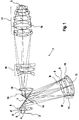
- the rays 4, 5 emanating from the reticle 2 occur first with a lens 6 adjacent to the reticle 2 positive refractive power.
- the edge rays of the beam 5 pass through the entry surface of the lens 6 at points A, A 'a.
- the distance between points A and A ' is small in relation to the free aperture of the lens 6.
- the beams 4, 5 from one plan mirror surface 7 in the drawing plane in one obtuse angles in the direction of one of three individual lenses 8, 9, 10 existing lens group 11 is reflected.
- the Edge rays of the beam 5 pass through the entrance surface the lens 8 at points B, B '.
- the distance between points B, B ' is approximate equal to the free aperture of the lenses 8, 9, 10.
- the ratio between the distance A, A 'or B, B', i.e. the distance between the points of impact of the marginal rays, which start from a field point of reticle 2, on an optical component and the free aperture this optical component is called the subaperture ratio in the following called.
- the beams 4, 5 hit after a first pass through the lens group 11 to a concave mirror 12.
- This has a reflective layer that from a Support body, not shown, is worn.
- the refractive power the lens 6 and the lens group 11 is such that the Concave mirror 12 in a pupil plane of the projection lens 1 lies.
- the subaperture ratio is in the Lenses 8, 9, 10 of the lens group 11 and in the concave mirror 12 approximately equal to 1 because these optical components lie in or near a pupil plane.
- the ray bundle 4, 5 belonging to a field point takes practically the entire free aperture of this optical components.
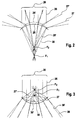
- the imaging ratios at a convex refractive or reflective surface which is due to the Illumination occurring residual heat and thereby expands, shows Figure 2.
- Such residual absorptions can e.g. in the lens body, in the area of one of a carrier body worn reflection layer of a mirror or in the carrier body itself.
- each of the meridional sections show reflective or refractive surface Neglected opening errors.
- the one that occurs when heated Change the radius of curvature of the optical surface is also greatly exaggerated compared to the real case.
- the illuminating beam 20 hits from which six individual beams 26 are shown in FIG. 2, from above onto a convexly curved reflective or refractive surface 25.
- the surface 25 is a reflective Area.
- the six individual beams 26 reflected from surface 25 such that the illuminating beam is scattered.
- the from surface 25 reflected and solid lines are identified by reference numeral 27.
- the reflective Surface 25 thus acts as a diverging mirror a given negative focal length.
- Surface 25 ' the radius of curvature of which is smaller than that the "cold" surface 25.
- the heated surface 25 ' is in Figure 2 shown in dashed lines.
- This smaller radius of curvature means that the of the heated surface 25 'reflected individual rays 27', which are shown in dashed lines in Figure 2, on the heated surface 25 'are scattered more than this was the case with the cold surface 25. Overall works thus the heated surface 25 'as a more scattering mirror than the cold surface 25.
- the heated surface 25 ' has a smaller radius of curvature than the cold surface 25.
- the refractive power of the heated surface 25' is therefore greater than that of the cold surface 25, so that the individual beams 28 'refracted on the heated surface 25' (shown in dashed lines) unite in a focal point F 2 whose distance from the entry surface is less than the distance from the focal point F 1 to the entry surface.
- the heated refractive surface 25 ′ therefore represents a collecting surface with a shorter focal length than the cold surface 25.
- Figure 3 are in a representation analogous to Figure 2 Imaging ratios with a concave reflective or refractive surface 30 shown.
- the surface 30 acts as a reflecting surface, that is to say in the case of the mirror 12 from FIG. 1, the incident individual beams 26 of the illuminating beam 20 are reflected as individual beams 27 and unite in a focal point F 1 .
- heating takes place through residual absorption. Analogously to what has been stated in connection with FIG. 2, this leads to a lifting of the surface 30, which is strongest in the central region of the surface 30.
- the heated area is designated 30 '. It has a larger radius of curvature than the unheated surface 30. This results in that of the heated surface.
- 30 'reflected individual rays 27' collect in a focal point F 2 which is at a greater distance from the collecting surface than the focal point F 1 from the cold surface 30.
- the concave surface 30 'thus acts as a collecting mirror with a larger focal length due to the heating.
- the effect is also in FIG. 3 a heating concave refractive surface 30 shown.
- the surface 30 acts as a weaker when heated Diffusing lens compared to the diffusing effect when cold.
- the refractive surface 25 and reflective surface 30 each by a focal length specified collection effect.
- the collecting effect of surface 25 increases with heating and the collecting effect of the mirror 30 with the heating from. It is therefore possible, by appropriate selection of the Materials of the support of the refractive surface 25, that is a lens body, and the support body for the mirror surface 30 as well as by a suitable specification of the output focal lengths of surfaces 25 and 30, the distance between them two optical components as well as other parameters (see u.) to achieve an imaging behavior in which the changes in the image caused by the warming compensate.
- the three lenses are used 8, 9, 10 of the lens group 11 as optical compensation elements for the heating behavior of the mirror 12.
- the concave mirror 12 has a reflection layer, which is applied to a mirror support made of the glass material BK7.
- the mirror support can also be made from the glass material Zerodur.
- the lenses 8, 9, 10 are made of calcium fluoride (CaF 2 ).
- the residual absorptions in the lens bodies or in the Reflection layer of the concave mirror 12 are in the Wavelength of 193.3 nm in the alcohol range.
- the Zernike coefficient of the wavefront deformation different image errors can be assigned.
- one Field curvature corresponds to a certain form the field varying value of Z4.
- a constant value for Z4 corresponds to defocusing.
- Z17 corresponds to the Vierwellmaschine.
- the lighting settings listed in the table denote different projection light distributions in the pupil plane, e.g. through a corresponding aperture in a pupil plane in a in the beam path in front of the Reticle 2 lying lighting optics for the light source the projection exposure system (not shown) can be generated.
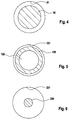
- Three examples of such lighting settings are shown in Figures 4 to 6. in this connection is a schematic section perpendicular to optical axis of the projection exposure system 1 in a pupil plane.
- FIG. 1 A so-called conventional lighting setting is shown in which a homogeneous illumination beam 20 in the pupil plane shown Cross section with a circular boundary.
- the Illumination beam bundle 20 lies coaxially in the free aperture 21 of the optics of the projection lens 1 such that the relationship between the numerical Aperture of the illuminating beam 20 and through the free aperture 21 predetermined numerical aperture of the Optics of the projection lens 1 is approximately 0.5.
- annular lighting setting shown in FIG. 5 is an illuminating beam 120 annular in the pupil plane shown, so that in a central unlit central region of the pupil plane 122 is present.
- the ratio of through the outer edge of the illumination beam 20 predetermined numerical Aperture of the lighting and that of the free Aperture 121 predetermined numerical aperture of the optics of the projection lens 1 lies in this lighting setting typically between 0.5 and 0.8.
- the lighting setting is a homogeneous beam of lighting 220 before, which has a cross section has circular boundary.
- the illuminating beam 20 has one much smaller diameter than the illuminating beam 20 of Figure 4, so that the coherent Illumination setting of Figure 6 that described above Ratio of numerical apertures at typically 0.3.
- the table shows that the changes the wavefront deformation caused by the mirror by the changes caused by the lenses 8 to 10 at least partially compensate.
- the ones from Mirror and changes caused by the lenses always opposite sign, so that the absolute amount the change in imaging in the overall system from mirrors and lenses is always smaller than the absolute value of the maximum single contribution.
- the changes in the Zernike coefficients were as follows calculated: First of all, from the given Lighting setting and from the diffraction characteristics of a reticle a location-dependent illumination angle distribution when illuminating each individual to be considered optical component (8, 9, 10, 12) determined. Subsequently the radiation energy distributions were based on the individual optical components (8, 9, 10, 12) are calculated. This resulted in the individual optical components (8, 9, 10, 12) absorbed radiation energy determined. Using a finite element method, the Temperature distribution and the material deformation of the individual optical components (8, 9, 10, 12) are calculated. From this the contributions to image defects (i.e. the changes the Zernik coefficient) due to the thermally induced Changes in refractive index and material deformation for each of the individual optical components (8, 9, 10, 12) calculated.
- the combination of a reflective one has an analogous effect convex surface 25 (see FIG. 2) and a refractive concave surface 30 (see FIG. 3) from the beam path be run through one after the other.
- heating leads to a concave refractive surface 30 to make their scattering effect weaker becomes.
- the following additional materials can be used for the mirror support: material Thermal expansion coefficient ( ⁇ in ⁇ m / [m K]) Zerodur -0.1 to 0.1 silicon 0.5 BK3 6.1 SK1 7.1 BK7 8.3 BK6 9.1 FK51 15.3 FK54 16.5
- the optical components 8 to 12 and the optical Components of the lens group 17, which are all in the Proximity of a pupil plane of the projection objective 1 all have a subaperture ratio close to 1.
- These Components are positioned optically equivalent and can be used as compensation elements. It is therefore z. B. possible, optical heating effects, that occur at the mirror 12 through one or all lenses to compensate for the lens group 17.
- lighting-induced heating of the optical components assigned to one another other parameters can be influenced.
- this is an additional targeted heating of optical components or areas of these through attached heating elements or by coatings that absorb unnecessary projection light, one targeted cooling of optical components or a called targeted passive heat dissipation.
- Heating, cooling or heat dissipation elements attached to a reflective Surface can be coupled both in Peripheral area of the surface as well as behind the reflection surface, that is on the opposite side of the irradiated side Side of the reflection surface, may be arranged.
- a coupling of heating, cooling or heat dissipation elements usually takes place in the case of transmissive elements Circumference area to avoid loss of projection light.
Landscapes
- Physics & Mathematics (AREA)
- General Physics & Mathematics (AREA)
- Health & Medical Sciences (AREA)
- Epidemiology (AREA)
- Engineering & Computer Science (AREA)
- Environmental & Geological Engineering (AREA)
- Optics & Photonics (AREA)
- Public Health (AREA)
- Life Sciences & Earth Sciences (AREA)
- Atmospheric Sciences (AREA)
- Toxicology (AREA)
- Lenses (AREA)
- Exposure Of Semiconductors, Excluding Electron Or Ion Beam Exposure (AREA)
- Exposure And Positioning Against Photoresist Photosensitive Materials (AREA)
Abstract
Description
Dies führt zur Möglichkeit, eine Kompensation der beleuchtungsinduzierten Abbildungsänderungen herbeizuführen.
- Figur 1
- ein katadioptrisches Projektionsobjektiv für die Mikro-Lithographie;
- Figur 2
- Brechungs- bzw. Reflexionsverhältnisse an einer konvexen sphärischen Fläche, deren Krümmungsradius durch eine beleuchtungsinduzierte Erwärmung abnimmt;
- Figur 3
- Brechungs- bzw. Reflexionsverhältnisse an einer konkaven sphärischen Fläche, deren Krümmungsradius durch eine beleuchtungsinduzierte Erwärmung zunimmt;
- Figuren 4 bis 6
- alternative Beleuchtungssettings für das Projektionsobjektiv von Figur 1.
| Konventionelles Setting | Annulares Setting | Kohärentes Setting | ||||
| Zernikekoeffizient der Wellenfrontdeformation (in nm) | Spiegel 12 | Linsen 8-10 | Spiegel 12 | Linsen 8-10 | Spiegel 12 | Linsen 8-10 |
| Z4 | -35,5 | 22,4 | -27,5 | 7,2 | -33,5 | 7,2 |
| Z9 | 3,1 | -5,7 | -3,7 | 3,2 | -5,5 | 5,1 |
| Z17 | 1,4 | -2,2 | -1,1 | 1,8 | 6,6 | -10,0 |
| Material | Thermischer Ausdehnungskoeffizient (α in µm/[m K] ) |
| Zerodur | -0,1 bis 0,1 |
| Silizium | 0,5 |
| BK3 | 6,1 |
| SK1 | 7,1 |
| BK7 | 8,3 |
| BK6 | 9,1 |
| FK51 | 15,3 |
| FK54 | 16,5 |
Claims (23)
- Projektionsbelichtungsanlage, insbesondere für die Mikro-Lithographie, mit einem katadioptrischen Projektionsobjektiv und einer Lichtquelle,
dadurch gekennzeichnet, daßa) mindestens ein Spiegel (12) und mindestens eine diesem zugeordnete Linse (8, 9, 10) des Projektionsobjektivs (1) aus in Abhängigkeit von einer gegebenen Lichtintensitätsverteilung im Projektionsobjektiv (1) derart gewählten Materialien sind undb) die Position des Spiegels (12) und die Position der Linse (8, 9, 10) innerhalb des Projektionsobjektivs (1) derart gleichartig sind,c) daß Abbildungsänderungen des Projektionsobjektivs (1), die auf einer beleuchtungsinduzierten Abbildungsänderung der Reflexionsfläche des Spiegels (12) beruhen, beleuchtungsinduzierten Abbildungsänderungen der Linse (8, 9, 10) entgegenwirken. - Projektionsbelichtungsanlage nach Anspruch 1, dadurch gekennzeichnet, daß sich die Subaperturverhältnisse des Spiegels (12) und der Linse (8, 9, 10) an ihren jeweiligen Positionen innerhalb des Projektionsobjektivs (1) um weniger als 25% unterscheiden.
- Projektionsbelichtungsanlage nach Anspruch 1 oder 2, dadurch gekennzeichnet, daß mehr als eine Linse (8, 9, 10) dem Spiegel (12) zugeordnet ist.
- Projektionsbelichtungsanlage nach Anspruch 3, dadurch gekennzeichnet, daß genau drei Linsen (8, 9, 10) dem Spiegel (12) zugeordnet sind.
- Projektionsbelichtungsanlage nach Anspruch 3, dadurch gekennzeichnet, daß genau drei Linsen (8, 9, 10) dem Spiegel (12) zugeordnet sind.
- Projektionsbelichtungsanlage nach einem der vorhergehenden Ansprüche, dadurch gekennzeichnet, daß der Spiegel und die ihm zugeordneten Linsen eine Gruppe optischer Komponenten bilden, wobei die Linsen innerhalb der Gruppe derart ausgewählt und angeordnet sind, daß die Abbildungsänderungen der Linsen innerhalb der Gruppe die Abbildungsänerungen des Spiegels kompensieren.
- Projektionsbelichtungsanlage nach einem der vorhergehenden Ansprüche, dadurch gekennzeichnet, daß die Linse (8, 9, 10) einen Linsenkörper aus CaF2 aufweist.
- Projektionsbelichtungsanlage nach einem der vorhergehenden Ansprüche, dadurch gekennzeichnet, daß der Spiegel (12) einen Spiegelträger aus einem der Glasmaterialien BK3, BK6 oder BK7 aufweist.
- Projektionsbelichtungsanlage nach einem der Ansprüche 1 bis 7, dadurch gekennzeichnet, daß der Spiegel (12) einen Spiegelträger aus dem Glasmaterial SK1 aufweist.
- Projektionsbelichtungsanlage nach einem der Ansprüche 1 bis 7, dadurch gekennzeichnet, daß der Spiegel (12) einen Spiegelträger aus einem der Glasmaterialien FK51 oder FK54 aufweist.
- Projektionsbelichtungsanlage nach einem der Ansprüche 1 bis 7, dadurch gekennzeichnet, daß der Spiegel (12) einen Spiegelträger aus dem Glasmaterial Zerodur aufweist.
- Projektionsbelichtungsanlage nach einem der Ansprüche 1 bis 7, dadurch gekennzeichnet, daß der Spiegel (12) einen Spiegelträger aus einkristallinem Silizium aufweist.
- Projektionsbelichtungsanlage nach einem der vorhergehenden Ansprüche, gekennzeichnet durch ein konventionelles Beleuchtungssetting.
- Projektionsbelichtungsanlage nach einem der Ansprüche 1 bis 13, gekennzeichnet durch ein kohärentes Beleuchtungssetting.
- Projektionsbelichtungsanlage nach einem der Ansprüche 1 bis 13, gekennzeichnet durch ein annulares Beleuchtungssetting.
- Projektionsbelichtungsanlage nach einem der vorhergehenden Ansprüche, gekennzeichnet durch eine Heizeinrichtung für den Spiegel (12) und/oder die Linse (8, 9, 10) zum zusätzlichen Ausgleich der beleuchtungsinduzierten Abbildungsänderungen.
- Projektionsbelichtungsanlage nach Anspruch 16, dadurch gekennzeichnet, daß die Heizeinrichtung eine lichtabsorbierende Beschichtung des Spiegels (12) und/oder der Linse (8, 9, 10) umfaßt.
- Projektionsbelichtungsanlage nach Anspruch 16 oder 17, dadurch gekennzeichnet, daß die Heizeinrichtung mindestens ein aktives Heizelement umfaßt, das am Umfang der Linse und/oder des Spiegels (12) angeordnet ist.
- Projektionsbelichtungsanlage nach einem der Ansprüche 16 bis 18, dadurch gekennzeichnet, daß die Heizeinrichtung mindestens ein aktives Heizelement umfaßt, das hinter der Reflexionsfläche des Spiegels (12) am Spiegelträger angeordnet ist.
- Projektionsbelichtungsanlage nach einem der vorhergehenden Ansprüche, gekennzeichnet durch eine Kühleinrichtung für den Spiegel (12) und/oder die Linse (8, 9, 10) zum zusätzlichen Ausgleich der beleuchtungsinduzierten Abbildungsänderungen.
- Projektionsbelichtungsanlage nach Anspruch 20, dadurch gekennzeichnet, daß die Kühleinrichtung mindestens eine thermische Kontaktfläche zur Ableitung der beleuchtungsinduzierten Erwärmung des Spiegels (12) und/ oder der Linse (8, 9, 10) aufweist.
- Projektionsbelichtungsanlage nach Anspruch 20 oder 21, dadurch gekennzeichnet, daß die Kühleinrichtung mindestens ein aktives Kühlelement umfaßt, das am Umfang der Linse und/oder des Spiegels (12) angeordnet ist.
- Projektionsbelichtungsanlage nach einem der Ansprüche 20 bis 22, dadurch gekennzeichnet, daß die Kühleinrichtung mindestens ein aktives Kühlelement umfaßt, das hinter der Reflexionsfläche des Spiegels (12) am Spiegelträger angeordnet ist.
Applications Claiming Priority (2)
| Application Number | Priority Date | Filing Date | Title |
|---|---|---|---|
| DE10040998A DE10040998A1 (de) | 2000-08-22 | 2000-08-22 | Projektionsbelichtungsanlage |
| DE10040998 | 2000-08-22 |
Publications (2)
| Publication Number | Publication Date |
|---|---|
| EP1182507A2 true EP1182507A2 (de) | 2002-02-27 |
| EP1182507A3 EP1182507A3 (de) | 2005-03-23 |
Family
ID=7653258
Family Applications (1)
| Application Number | Title | Priority Date | Filing Date |
|---|---|---|---|
| EP01116088A Withdrawn EP1182507A3 (de) | 2000-08-22 | 2001-07-03 | Projektionsbelichtungsanlage |
Country Status (4)
| Country | Link |
|---|---|
| US (1) | US6593998B2 (de) |
| EP (1) | EP1182507A3 (de) |
| JP (1) | JP2002107632A (de) |
| DE (1) | DE10040998A1 (de) |
Cited By (1)
| Publication number | Priority date | Publication date | Assignee | Title |
|---|---|---|---|---|
| WO2008138560A1 (de) * | 2007-05-14 | 2008-11-20 | Carl Zeiss Smt Ag | Projektionsobjektiv und projektionsbelichtungsanlage für die mikrolithographie |
Families Citing this family (14)
| Publication number | Priority date | Publication date | Assignee | Title |
|---|---|---|---|---|
| JP3588095B2 (ja) * | 2001-12-04 | 2004-11-10 | エイエスエムエル ネザランドズ ベスローテン フエンノートシャップ | リトグラフ投影装置、装置の製造方法および光学要素を製造する方法 |
| WO2004036316A1 (en) * | 2002-10-15 | 2004-04-29 | Carl Zeiss Smt Ag | Optical arrangement and method of specifying and performing a deformation of an optical surface of an optical element being part of the optical arrangement |
| DE10317662A1 (de) * | 2003-04-17 | 2004-11-18 | Carl Zeiss Smt Ag | Projektionsobjektiv, mikrolithographische Projektionsbelichtungsanlage und Verfahren zur Herstellung einer Halbleiterschaltung |
| EP1614007A1 (de) * | 2003-04-17 | 2006-01-11 | Carl Zeiss SMT AG | Optisches system, verfahren zum ändern der optischen verzögerung in diesem system und photolithographisches gerät |
| AU2003229725A1 (en) * | 2003-04-24 | 2004-11-19 | Carl Zeiss Smt Ag | Projection optical system |
| US7375794B2 (en) * | 2004-08-04 | 2008-05-20 | Asml Netherlands B.V. | Lithographic apparatus and device manufacturing method |
| DE102006038398A1 (de) * | 2006-08-15 | 2008-02-21 | Carl Zeiss Smt Ag | Projektionsobjektiv einer mikrolithographischen Projektionsbelichtungsanlage |
| DE102006039895A1 (de) * | 2006-08-25 | 2008-03-13 | Carl Zeiss Smt Ag | Verfahren zur Korrektur von durch Intensitätsverteilungen in optischen Systemen erzeugten Abbildungsveränderungen sowie entsprechendes optisches System |
| JP5440759B2 (ja) * | 2009-05-08 | 2014-03-12 | 株式会社ニコン | 変倍式望遠光学系及びこれを備える光学装置 |
| DE102009029776B3 (de) * | 2009-06-18 | 2010-12-02 | Carl Zeiss Smt Ag | Optisches Element |
| JP2012181220A (ja) * | 2009-07-02 | 2012-09-20 | Asahi Glass Co Ltd | ArFリソグラフィ用ミラー、およびArFリソグラフィ用光学部材 |
| US8953157B2 (en) * | 2012-02-01 | 2015-02-10 | Wisconsin Alumni Research Foundation | Monolithic fiber optic sensor assembly |
| US10283342B2 (en) * | 2015-12-06 | 2019-05-07 | Kla-Tencor Corporation | Laser sustained plasma light source with graded absorption features |
| DE102015225509A1 (de) * | 2015-12-16 | 2017-06-22 | Carl Zeiss Smt Gmbh | Reflektives optisches Element |
Family Cites Families (16)
| Publication number | Priority date | Publication date | Assignee | Title |
|---|---|---|---|---|
| US4278330A (en) * | 1979-05-14 | 1981-07-14 | Applied Systems Corporation | Catadioptric virtual-zoom optical system |
| US4344676A (en) * | 1979-10-09 | 1982-08-17 | The Perkin-Elmer Corporation | Single element spherical surfaced optics insensitive to wavelength and temperature |
| JPS576820A (en) * | 1980-06-17 | 1982-01-13 | Canon Inc | Optical system for copying having temperature compensating lens |
| JPS59211013A (ja) * | 1983-05-16 | 1984-11-29 | Fuji Photo Optical Co Ltd | 温度補償を施したプラスチツク対物レンズ系 |
| JPH0823627B2 (ja) * | 1989-09-08 | 1996-03-06 | 大日本スクリーン製造株式会社 | 色消しレンズ系 |
| JP2995371B2 (ja) * | 1992-11-12 | 1999-12-27 | セイコーインスツルメンツ株式会社 | X線反射鏡用材料 |
| JP3368091B2 (ja) * | 1994-04-22 | 2003-01-20 | キヤノン株式会社 | 投影露光装置及びデバイスの製造方法 |
| JPH0817719A (ja) * | 1994-06-30 | 1996-01-19 | Nikon Corp | 投影露光装置 |
| JP3487383B2 (ja) * | 1995-07-06 | 2004-01-19 | 株式会社ニコン | 露光装置及びそれを用いる素子製造方法 |
| US6043863A (en) * | 1996-11-14 | 2000-03-28 | Nikon Corporation | Holder for reflecting member and exposure apparatus having the same |
| JPH10340850A (ja) * | 1997-06-05 | 1998-12-22 | Nikon Corp | 露光装置 |
| EP1039510A4 (de) * | 1997-11-14 | 2003-11-12 | Nikon Corp | Belichtungsapparat und herstellungsverfahren, und belichtungsverfahren |
| EP1293830A1 (de) * | 1998-06-08 | 2003-03-19 | Nikon Corporation | Verfahren und Vorrichtung zur Projektionsbelichtung |
| DE19939088A1 (de) * | 1998-08-18 | 2000-02-24 | Nikon Corp | Belichtungsvorrichtung und -verfahren |
| US6398374B1 (en) * | 1998-12-31 | 2002-06-04 | The Regents Of The University Of California | Condenser for ring-field deep ultraviolet and extreme ultraviolet lithography |
| US6404547B1 (en) * | 2000-03-01 | 2002-06-11 | Raytheon Company | Semi-active focus and thermal compensation of a centrally-obscured reflective telescope |
-
2000
- 2000-08-22 DE DE10040998A patent/DE10040998A1/de not_active Ceased
-
2001
- 2001-07-03 EP EP01116088A patent/EP1182507A3/de not_active Withdrawn
- 2001-08-21 US US09/934,252 patent/US6593998B2/en not_active Expired - Lifetime
- 2001-08-21 JP JP2001249993A patent/JP2002107632A/ja active Pending
Cited By (1)
| Publication number | Priority date | Publication date | Assignee | Title |
|---|---|---|---|---|
| WO2008138560A1 (de) * | 2007-05-14 | 2008-11-20 | Carl Zeiss Smt Ag | Projektionsobjektiv und projektionsbelichtungsanlage für die mikrolithographie |
Also Published As
| Publication number | Publication date |
|---|---|
| DE10040998A1 (de) | 2002-03-14 |
| JP2002107632A (ja) | 2002-04-10 |
| US20020075466A1 (en) | 2002-06-20 |
| EP1182507A3 (de) | 2005-03-23 |
| US6593998B2 (en) | 2003-07-15 |
Similar Documents
| Publication | Publication Date | Title |
|---|---|---|
| DE69222729T2 (de) | Optisches System zur wiederholten Abbildung mit refraktiven und diffraktiven optischen Elementen | |
| DE19963588C2 (de) | Optische Anordnung | |
| DE3787035T2 (de) | Optisches Projektionssystem für Präzisionskopien. | |
| EP1984789B1 (de) | Beleuchtungssystem für die mikro-lithographie, projektionsbelichtungsanlage mit einem derartigen beleuchtungssystem | |
| DE19942281A1 (de) | Projektionsobjektiv | |
| DE10040998A1 (de) | Projektionsbelichtungsanlage | |
| DE19653983A1 (de) | REMA-Objektiv für Mikrolithographie-Projektionsbelichtungsanlagen | |
| EP1258780A2 (de) | Optisches Abbildungssystem mit Polarisationsmitteln und Quarzkristallplatte hierfür | |
| CH656013A5 (de) | Afokales linsenfernrohr mit zwei vergroesserungseinstellungen. | |
| DE102009006685A1 (de) | Beleuchtungssystem für die Mikro-Lithographie | |
| EP1235112B1 (de) | Teilobjektiv für Beleuchtungssystem | |
| DE102009049640B4 (de) | Projektionsobjektiv für eine mikrolithographische EUV-Projektionsbelichtungsanlage | |
| DE102007046419A1 (de) | Verfahren zum Verbessern der Abbildungseigenschaften eines optischen Systems sowie derartiges optisches System | |
| DE112011102900B4 (de) | Abbildungssystem | |
| DE102019108084A1 (de) | Zoomoptik | |
| CH653446A5 (de) | Spiegellinsenobjektiv von hohem oeffnungsverhaeltnis. | |
| DE112013003558B4 (de) | Zoombares Strahlaufweitungssystem für einen Ultraviolettlaser und Laserbearbeitungsvorrichtung | |
| DE69121133T2 (de) | Objektivlinsensystem zur Anwendung in einem Mikroskop | |
| DE102024205431A1 (de) | Achromatische abbildende Optik | |
| DE102024205432A1 (de) | Achromatische abbildende Optik | |
| DE102023205966A1 (de) | Optisches Element mit Temperierkanälen und Lithographiesystem | |
| DE102024203031A1 (de) | Vorrichtung, Halteeinrichtung, Anordnung, System und Verfahren zur Halterung eines optischen Elements; Lithografiesystem | |
| DE102022205143A1 (de) | Optisches Element sowie Baugruppe und optisches System damit | |
| DE102021208664A1 (de) | Spiegel für eine Projektionsbelichtungsanlage der Mikrolithographie | |
| DE19964079C1 (de) | Maksutov-Cassegrain-System kurzer Baulänge |
Legal Events
| Date | Code | Title | Description |
|---|---|---|---|
| PUAI | Public reference made under article 153(3) epc to a published international application that has entered the european phase |
Free format text: ORIGINAL CODE: 0009012 |
|
| AK | Designated contracting states |
Kind code of ref document: A2 Designated state(s): AT BE CH CY DE DK ES FI FR GB GR IE IT LI LU MC NL PT SE TR |
|
| AX | Request for extension of the european patent |
Free format text: AL;LT;LV;MK;RO;SI |
|
| RAP1 | Party data changed (applicant data changed or rights of an application transferred) |
Owner name: CARL-ZEISS-STIFTUNG TRADING AS CARL ZEISS Owner name: CARL ZEISS |
|
| RAP1 | Party data changed (applicant data changed or rights of an application transferred) |
Owner name: CARL ZEISS |
|
| RAP1 | Party data changed (applicant data changed or rights of an application transferred) |
Owner name: CARL ZEISS SMT AG |
|
| PUAL | Search report despatched |
Free format text: ORIGINAL CODE: 0009013 |
|
| AK | Designated contracting states |
Kind code of ref document: A3 Designated state(s): AT BE CH CY DE DK ES FI FR GB GR IE IT LI LU MC NL PT SE TR |
|
| AX | Request for extension of the european patent |
Extension state: AL LT LV MK RO SI |
|
| AKX | Designation fees paid | ||
| REG | Reference to a national code |
Ref country code: DE Ref legal event code: 8566 |
|
| STAA | Information on the status of an ep patent application or granted ep patent |
Free format text: STATUS: THE APPLICATION IS DEEMED TO BE WITHDRAWN |
|
| 18D | Application deemed to be withdrawn |
Effective date: 20050924 |