EP1182432A2 - Flusssensor mit Gehäuse - Google Patents
Flusssensor mit Gehäuse Download PDFInfo
- Publication number
- EP1182432A2 EP1182432A2 EP01118861A EP01118861A EP1182432A2 EP 1182432 A2 EP1182432 A2 EP 1182432A2 EP 01118861 A EP01118861 A EP 01118861A EP 01118861 A EP01118861 A EP 01118861A EP 1182432 A2 EP1182432 A2 EP 1182432A2
- Authority
- EP
- European Patent Office
- Prior art keywords
- flow sensor
- sensor according
- measuring channel
- semiconductor chip
- housing parts
- Prior art date
- Legal status (The legal status is an assumption and is not a legal conclusion. Google has not performed a legal analysis and makes no representation as to the accuracy of the status listed.)
- Granted
Links
Images


Classifications
-
- G—PHYSICS
- G01—MEASURING; TESTING
- G01F—MEASURING VOLUME, VOLUME FLOW, MASS FLOW OR LIQUID LEVEL; METERING BY VOLUME
- G01F1/00—Measuring the volume flow or mass flow of fluid or fluent solid material wherein the fluid passes through a meter in a continuous flow
- G01F1/68—Measuring the volume flow or mass flow of fluid or fluent solid material wherein the fluid passes through a meter in a continuous flow by using thermal effects
- G01F1/684—Structural arrangements; Mounting of elements, e.g. in relation to fluid flow
- G01F1/6845—Micromachined devices
-
- G—PHYSICS
- G01—MEASURING; TESTING
- G01F—MEASURING VOLUME, VOLUME FLOW, MASS FLOW OR LIQUID LEVEL; METERING BY VOLUME
- G01F1/00—Measuring the volume flow or mass flow of fluid or fluent solid material wherein the fluid passes through a meter in a continuous flow
- G01F1/68—Measuring the volume flow or mass flow of fluid or fluent solid material wherein the fluid passes through a meter in a continuous flow by using thermal effects
- G01F1/684—Structural arrangements; Mounting of elements, e.g. in relation to fluid flow
- G01F1/688—Structural arrangements; Mounting of elements, e.g. in relation to fluid flow using a particular type of heating, cooling or sensing element
- G01F1/69—Structural arrangements; Mounting of elements, e.g. in relation to fluid flow using a particular type of heating, cooling or sensing element of resistive type
- G01F1/692—Thin-film arrangements
Definitions
- the invention relates to a flow sensor according to Preamble of claim 1.
- a known flow sensor of this type has a two-part housing that forms a measuring channel.
- a semiconductor chip with a sensor arrangement is on the Wall of the measuring channel arranged.
- the semiconductor chip surrounding sealing ring is provided, which against a counterholder presses, the counterholder of one of the housing parts is formed.
- the semiconductor chip For connecting the semiconductor chip with the outside world there is at least one conductor track between the sealing ring and the counter holder to the outside guided.
- the at least one conductor track is preferably arranged on a flexible conductor foil. It is also possible to place the conductor track directly on one to fix the housing parts.
- the measuring channel is preferably formed as a groove in configured the surface of a first housing part.
- connecting cables e.g. in the form of bores or holes, be provided by one or more of the housing parts extend.
- the sealing ring can be on said surface can be arranged around the groove. With this arrangement, the measuring channel can be used on all sides be sealed.
- the semiconductor chip is preferably in one Deepening of the second housing part and its top (i.e. the side on which the sensor arrangement is located ) is flush with the wall of the measuring channel, see above that the flow conditions are as laminar as possible.
- the top of the semiconductor chip touches the first part of the housing.
- a spacer is provided in the bottom of the depression, which is elastic due to the pressing force of the housing parts or is plastically deformed and the semiconductor chip presses against the first part of the housing so that when assembling the housing parts an accurate and permanent Positioning the semiconductor chip relative to Measurement channel results.
- the spacer can e.g. of surveys be formed in the bottom of the depression.
- the flow sensor according to the invention is for Measurement of the flow of liquids or gases in normal or increased pressure ratios.
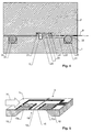
- the flow sensor shown in the figures has a first housing part 1, a second housing part 2 and one essentially between the housing parts 1, 2 pinched semiconductor chip 3. In Fig. 1 these parts are shown spaced apart. in the In operation, however, the housing parts 1, 2 lie one on top of the other and clamp the semiconductor chip 3 between them.
- a straight groove 5 which, together with the adjacent second housing part 2, forms a measuring channel.
- the mouths of the connecting lines 6 of Surround seals 7 are connected.
- a possible structure of the semiconductor chip 3 is shown in Fig. 5. It has a semiconductor substrate 10, on the top 11 a sensor arrangement is integrated. This includes in a conventional manner a heating element 12 between two temperature sensors 13a, 13b.
- the temperature sensors 13a, 13b lie in the direction of flow 14 of the medium to be measured in front of or behind the heating element 12, so that their temperature difference is a measure for the flow velocity or the mass flow.
- the sensor arrangement is on a membrane 15 arranged, which lies above an opening 16, which is extends through the substrate 10.
- the sensor arrangement faces the measuring channel. He is flexible Conductor foil 9 connected, which led out of the sensor is. For this there is a in the second housing part Indentation 22 is provided.
- the conductor track film 9 is made e.g. from a thin plastic carrier, on or in which Conductor tracks 9 'are arranged.
- the total thickness of the Conductor foil 9 is preferably less than 100 microns.
- the elevations 21 are preferably in one piece connected to the second housing part. You need to not be pyramidal, in the undeformed state however, they should preferably be pointed so that their tips are deformed with little effort can. They can be plastically or elastically deformable his.
- the recess 20 has two transverse sides 26a, 26b (FIG. 3) parallel to the measuring channel and two long sides 27a, 27b perpendicular to the measuring channel. At the ends of one the transverse sides 26b are two bulges 28a, 28b intended. Runs between the bulges 28a, 28b the transverse side 26b is straight and forms a defined stop, which allows the semiconductor chip 3 across Position the measuring channel in an exact manner. The bulges ensure that the semiconductor chip 3 is not on any rounds due to manufacturing reasons the corners of the recess 20 is present.
- the recess 20 is dimensioned so that between the long sides 27a, 27b and the semiconductor chip 3 some space remains so that the area between the semiconductor chip 3 and the bottom of the recess stands with the measuring channel. This ensures that both sides of the membrane 15 (Fig. 5) with the Measuring channel are connected so that the pressure drop across the membrane is substantially zero, which makes Damage to the membrane 15 due to high static or dynamic pressures can be avoided.
- the conductor track film 9 from the semiconductor chip 3 is between the sealing ring 31 and the inside of the second housing part 2 performed and from the sealing ring 31 acted upon.
- a sealant 32 e.g. Silicone.
- the semiconductor chip not arranged in the middle of the groove 5. Much more it is closer to the exit end 5b than to the entrance end 5a of the measuring channel. Because the medium to be measured flows from input end 5a to output end 5b itself due to the asymmetrical arrangement of the semiconductor chip 3 closer to the exit end 5b more laminar flow conditions at the measuring point.
- the housing parts 1, 2 are preferred prefabricated by injection molding. Then the sealing ring 31 into the recess 30 and the semiconductor chip 3 inserted into the recess 20. Now the sealant can 32 applied in the area of the conductor track film 9 become. Then the two housing parts 1, 2 on top of each other placed and screwed into screw holes 34 connected with each other.
- the housing parts 1, 2 can be made of plastic and / or metal. Especially at high pressures it is conceivable for the housing to be made of a plastic structure and to manufacture metal, the metal being the housing gives necessary strength and the plastic in the area the inside is provided where good sealing and Deformation properties are needed. In particular can also use the sealing ring as a sealing rib made of sealing material injection molding directly in the housing parts be shaped.
- connection lines are 6 arranged in the second housing part 2.
- the connection lines are 6 arranged in the second housing part 2.
- the Sealing ring 31 also mounted in the second housing part 2 , or it could be in both housing parts 1, 2 Sealing rings may be provided.
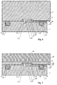
- FIG. 6 shows a section accordingly Fig. 4 shows the first embodiment.
- Fig. 6 shows a section accordingly Fig. 4 shows the first embodiment.
- Conductor foil 9 instead of Conductor foil 9 provided conductor tracks 9 ', which on second housing part 2 are attached. Under conductor tracks are electrical formed by a coating Understand lines that are much wider than thick are, so that they are not too big a deformation of the Effect sealing ring.
- the second housing part 2 consists of a Insulator or is on its bottom with an electrical insulating layer covered.
- the conductor tracks 9 ' are metal tracks that e.g. by galvanizing on the second housing part 2 were attached.
- For connection between the semiconductor chip 3 and the conductor tracks 9 ' are e.g. Bond wires 35 or other connecting lines intended.
- FIG. 7 A third version of the sensor is in Fig. 7, which also corresponds to a section Fig. 4 shows the first embodiment. Here too only the differences from the first execution described.
- Conductor foil 9 provided conductor tracks 9 'which a carrier plate 2a are arranged.
- the carrier plate 2a is reinforced on the back by a reinforcing plate 2b and forms with this the second housing part.
- the Carrier plate 2a is designed as a printed circuit board in which also the recess 20 for receiving the semiconductor chip is arranged.
- the semiconductor chip is preferably fixed in this recess 20 with an adhesive 38, in such a way that a pressure equalization between The front and back of the membrane 15 still take place can.
- the link between the Semiconductor chip 3 and the conductor tracks 9 'e.g. Bond wires 35 or other connecting lines are provided, and the Conductor tracks form connection points on the outside of the housing 36, which e.g. with supply wires or plug contacts can be provided.
- the conductor tracks 9 ' are preferably the second and third version similarly thin as the conductor foil 9 of the first embodiment, i.e. their thickness is preferably less than 100 microns.
- the sealing ring 31 is against the reinforcing plate 2b pressed, which in the present case the Counterhold forms.
- the carrier plate 2a is between the Sealing ring 31 and the reinforcing plate 2b to the outside guided.
- FIG. 8 A fourth version of the sensor is in Fig. 8 shown, which also corresponds to a section Fig. 4 shows the first embodiment.
- the fourth Execution corresponds to a few differences the third version. The differences are as follows describe.
- the carrier plate 2a provided on both sides with conductor tracks 9 'or 9 ".
- the semiconductor chip 3 is e.g. by means of bond wires 35, with conductor tracks 9 'on the underside of the carrier plate 2a connected.
- the bushings 39 are with a sealant 40 filled, so that a pressure equalization between the measuring channel and the top of the carrier plate 2a is prevented.
- the senor described here easily a pressure of to withstand more than 25 bar. It is suitable for flow measurements all kinds of gases and liquids.
Landscapes
- Physics & Mathematics (AREA)
- Fluid Mechanics (AREA)
- General Physics & Mathematics (AREA)
- Measuring Fluid Pressure (AREA)
- Measuring Volume Flow (AREA)
Abstract
Description
Claims (15)
- Flusssensor mit einem Gehäuse mit mindestens zwei Gehäuseteilen (1, 2), zwischen denen ein Messkanal gebildet wird, wobei zwischen den Gehäuseteilen an einer Wand des Messkanals ein Halbleiterchip (3) mit Sensoranordnung angeordnet ist, dadurch gekennzeichnet, dass zwischen mindestens zwei der Gehäuseteile (1, 2) ein den Messkanal und den Halbleiterchip (3) umgebender Dichtungsring (31) angeordnet ist, der gegen einen von einem der Gehäuseteile gebildeten Gegenhalter (2, 2b) drückt, wobei mindestens eine mit dem Halbleiterchip verbundene Leiterbahn (9') zwischen dem Dichtungsring (31) und dem Gegenhalter (2, 2b) nach aussen geführt ist.
- Flusssensor nach Anspruch 1, dadurch gekennzeichnet, dass die Leiterbahn (9') vom Dichtungsring (31) beaufschlagt ist.
- Flusssensor nach einem der Ansprüche 1 oder 2, dadurch gekennzeichnet, dass die mindestens eine Leiterbahn (9') auf einem der Gehäuseteile angeordnet ist.
- Flusssensor nach Anspruch 3, gekennzeichnet durch eine Printplatte (2a), welche mindestens einen Teil eines der Gehäuseteile bildet und auf der die mindestens eine Leiterbahn (9') angeordnet ist.
- Flusssensor nach Anspruch 4, dadurch gekennzeichnet, dass die Printplatte (2a) zwischen dem Dichtungsring (31) und dem Gegenhalter (2b) angeordnet ist.
- Flusssensor nach einem der Ansprüche 1 oder 2, dadurch gekennzeichnet, dass die mindestens eine Leiterbahn (9') auf einer flexiblen Leiterbahnfolie (9) angeordnet ist.
- Flusssensor nach einem der vorangehenden Ansprüche, dadurch gekennzeichnet, dass der Messkanal als Nut (5) in einer Oberfläche (4) mindestens eines der Gehäuseteile (1, 2) ausgestaltet ist, wobei der Dichtungsring (31) die Nut (5) umgibt, und dass in die Nut (5) zwei Anschlussleitungen (6) münden, wobei sich die Anschlussleitungen (6) durch mindestens einen der Gehäuseteile (1, 2) erstrecken.
- Flusssensor nach Anspruch 7, dadurch gekennzeichnet, dass der Dichtungsring (31) an der besagten Oberfläche (4), und insbesondere in einer Vertiefung (30) der Oberfläche (4), angeordnet ist.
- Flusssensor nach einem der vorangehenden Ansprüche, dadurch gekennzeichnet, dass der Messkanal als Nut (5) in einer Oberfläche (4) eines ersten Gehäuseteils (1) ausgestaltet ist, dass der Halbleiterchip (3) im wesentlichen bündig mit der Wand des Messkanals in einer Vertiefung (20) eines zweiten Gehäuseteils (2) liegt und vom ersten Gehäuseteil (1) beaufschlagt wird.
- Flusssensor nach Anspruch 9, dadurch gekennzeichnet, dass zwischen dem Halbleiterchip (3) und einem Boden der Vertiefung (20) mindestens ein Abstandhalter (21) angeordnet ist, wobei der Abstandhalter (21) von einer Andruckkraft, welche die Gehäuseteile (1, 2) aufeinander ausüben, plastisch und/oder elastisch deformiert ist.
- Flusssensor nach Anspruch 10, dadurch gekennzeichnet, dass der Abstandhalter (21) mehrere, vorzugsweise in undeformiertem Zustand spitz zulaufende, Erhebungen im Boden der Vertiefung umfasst, und insbesondere dass die Erhebungen einstückig mit dem zweiten Gehäuseteil (2) ausgeformt sind.
- Flusssensor nach einem der Ansprüche 9 bis 11, dadurch gekennzeichnet, dass die Vertiefung (20) eine Querseite (26b) parallel zum Messkanal aufweist, die an ihren Enden in je eine Ausbuchtung (28a, 28b) mündet, so dass die Querseite (26a) eine gerade Anschlagkante zum Positionieren des Halbleiterchips (3) senkrecht zum Messkanal bildet.
- Flusssensor nach einem der vorangehenden Ansprüche, dadurch gekennzeichnet, dass die Leiterbahn (9') im Bereich des Dichtungsrings (31) mit einer Dichtungsmasse (32) abgedichtet ist.
- Flusssensor nach einem der vorangehenden Ansprüche, dadurch gekennzeichnet, dass der Halbleiterchip (3) eine Membran (15) aufweist, auf welcher die Sensorandordnung angeordnet ist, wobei die Membran beidseitig mit dem Messkanal in Verbindung steht, so dass die über ihr abfallende Druckdifferenz im wesentlichen Null ist.
- Flusssensor nach einem der vorangehenden Ansprüche, dadurch gekennzeichnet, dass der Halbleiterchip (3) näher an einem Ausgangsende (5b) des Messkanals als an einem Eingangsende (5a) des Messkanals angeordnet ist.
Applications Claiming Priority (2)
| Application Number | Priority Date | Filing Date | Title |
|---|---|---|---|
| CH16442000 | 2000-08-23 | ||
| CH16442000 | 2000-08-23 |
Publications (3)
| Publication Number | Publication Date |
|---|---|
| EP1182432A2 true EP1182432A2 (de) | 2002-02-27 |
| EP1182432A3 EP1182432A3 (de) | 2002-08-28 |
| EP1182432B1 EP1182432B1 (de) | 2014-03-19 |
Family
ID=4565746
Family Applications (1)
| Application Number | Title | Priority Date | Filing Date |
|---|---|---|---|
| EP01118861.2A Expired - Lifetime EP1182432B1 (de) | 2000-08-23 | 2001-08-16 | Flusssensor mit Gehäuse |
Country Status (2)
| Country | Link |
|---|---|
| US (1) | US6729181B2 (de) |
| EP (1) | EP1182432B1 (de) |
Cited By (7)
| Publication number | Priority date | Publication date | Assignee | Title |
|---|---|---|---|---|
| EP1477781A1 (de) * | 2003-05-13 | 2004-11-17 | Berkin B.V. | Massendurchflussmesser |
| EP1396705A3 (de) * | 2002-08-27 | 2005-05-11 | Sensirion AG | Flussdetektor mit Durchführungen und Verfahren zu dessen Herstellung |
| EP2378254A3 (de) * | 2010-04-19 | 2012-03-14 | Honeywell International, Inc. | Robuster Sensor mit Abschlusskappe |
| US8256285B2 (en) | 2007-08-21 | 2012-09-04 | BELIMO Holding, AG | Flow sensor including a base member with a resilient region forming a flow channel and a cover member covering the flow channel |
| US8356514B2 (en) | 2011-01-13 | 2013-01-22 | Honeywell International Inc. | Sensor with improved thermal stability |
| US8640552B2 (en) | 2011-09-06 | 2014-02-04 | Honeywell International Inc. | MEMS airflow sensor die incorporating additional circuitry on the die |
| EP3537113A1 (de) | 2018-03-08 | 2019-09-11 | Sensirion AG | Vorrichtung zum messen des flusses eines fluids |
Families Citing this family (29)
| Publication number | Priority date | Publication date | Assignee | Title |
|---|---|---|---|---|
| US6794981B2 (en) * | 1998-12-07 | 2004-09-21 | Honeywell International Inc. | Integratable-fluid flow and property microsensor assembly |
| US20040154383A1 (en) * | 2002-12-11 | 2004-08-12 | Woolf Darin Kent | Multiple indicator flow meter system |
| JP4732732B2 (ja) * | 2004-10-20 | 2011-07-27 | 株式会社山武 | マイクロフローセンサ |
| EP1760437A1 (de) * | 2005-09-06 | 2007-03-07 | Sensirion AG | Verfahren zur Herstellung von Detektionsvorrichtungen |
| US20070176010A1 (en) * | 2006-01-06 | 2007-08-02 | Honeywell International Inc. | System for heating liquids |
| JP4845187B2 (ja) * | 2006-02-07 | 2011-12-28 | 株式会社山武 | センサのパッケージ構造及びこれを有するフローセンサ |
| WO2008046235A1 (en) * | 2006-10-18 | 2008-04-24 | Sensirion Holding Ag | A method for packaging integrated sensors |
| CN101641576B (zh) * | 2007-02-28 | 2011-11-09 | 株式会社山武 | 流量传感器 |
| DE202007003027U1 (de) * | 2007-03-01 | 2007-06-21 | Sensirion Ag | Vorrichtung zur Handhabung von Fluiden mit einem Flußsensor |
| EP2107347B1 (de) * | 2008-04-04 | 2016-08-31 | Sensirion AG | Flussdetektor mit Gehäuse |
| US7748268B2 (en) * | 2008-07-13 | 2010-07-06 | Brooks Instrument, Llc | Thermal flow meter |
| EP2154713B1 (de) * | 2008-08-11 | 2013-01-02 | Sensirion AG | Verfahren zur Herstellung einer Messvorrichtung mit einer Spannungsverminderungsschicht |
| EP2159558A1 (de) * | 2008-08-28 | 2010-03-03 | Sensirion AG | Verfahren zur Herstellung eines integrierten Drucksensors |
| EP2224218B1 (de) * | 2009-02-25 | 2018-11-28 | Sensirion Automotive Solutions AG | Sensor in einer geformten Verpackung und Herstellungsverfahren dafür |
| US9003877B2 (en) * | 2010-06-15 | 2015-04-14 | Honeywell International Inc. | Flow sensor assembly |
| US8418549B2 (en) * | 2011-01-31 | 2013-04-16 | Honeywell International Inc. | Flow sensor assembly with integral bypass channel |
| US20120001273A1 (en) * | 2010-07-02 | 2012-01-05 | Siargo Ltd. | Micro-package for Micromachining Liquid Flow Sensor Chip |
| JP5183683B2 (ja) * | 2010-07-02 | 2013-04-17 | 三菱電機株式会社 | 流量測定装置 |
| JP5496027B2 (ja) | 2010-09-09 | 2014-05-21 | 日立オートモティブシステムズ株式会社 | 熱式空気流量計 |
| EP2762865A1 (de) * | 2013-01-31 | 2014-08-06 | Sensirion Holding AG | Chemische Sensor und Verfahren zur Herstellung solch eines chemischen Sensors |
| US9612146B2 (en) | 2014-02-07 | 2017-04-04 | Honeywell International, Inc. | Airflow sensor with dust reduction |
| EP3032227B1 (de) | 2014-12-08 | 2020-10-21 | Sensirion AG | Flusssensorpaket |
| US9791307B2 (en) * | 2015-03-06 | 2017-10-17 | Alicat Scientific, Inc. | Systems and methods for detecting flow of a fluid |
| US9952079B2 (en) | 2015-07-15 | 2018-04-24 | Honeywell International Inc. | Flow sensor |
| US10444051B2 (en) | 2017-01-09 | 2019-10-15 | Georg Fischer Signet, LLC | Ultrasonic sensor assembly and method of manufacture |
| US10254143B2 (en) | 2017-01-13 | 2019-04-09 | Georg Fischer Signet Llc | Fluid-flow sensor assembly having reinforced body |
| US10620060B2 (en) | 2017-07-19 | 2020-04-14 | Georg Fischer Signet, LLC | Combined ultrasonic temperature and conductivity sensor assembly |
| US10302474B2 (en) | 2017-08-09 | 2019-05-28 | Georg Fischer Signet Llc | Insertion ultrasonic sensor assembly |
| US12656202B2 (en) * | 2022-05-31 | 2026-06-16 | Apple Inc. | Sensor module having an intermediate pedestal on which one or more die are mounted |
Citations (4)
| Publication number | Priority date | Publication date | Assignee | Title |
|---|---|---|---|---|
| US4548078A (en) | 1982-09-30 | 1985-10-22 | Honeywell Inc. | Integral flow sensor and channel assembly |
| DE68909195T2 (de) | 1988-12-23 | 1994-03-17 | Lucas Ind Plc | Elektrische Verbindungsanordnung und Verfahren zur Herstellung einer elektrischen Verbindung. |
| EP0513263B1 (de) | 1990-12-01 | 1995-10-18 | Robert Bosch Gmbh | Anordnung zur dichten durchführung eines leiters durch die wand eines gehäuses |
| WO2000011481A2 (de) | 1998-08-19 | 2000-03-02 | Siemens Aktiengesellschaft | Elektronische sensoranordnung |
Family Cites Families (11)
| Publication number | Priority date | Publication date | Assignee | Title |
|---|---|---|---|---|
| US4677850A (en) * | 1983-02-11 | 1987-07-07 | Nippon Soken, Inc. | Semiconductor-type flow rate detecting apparatus |
| US4829818A (en) * | 1983-12-27 | 1989-05-16 | Honeywell Inc. | Flow sensor housing |
| EP0172669A1 (de) | 1984-07-25 | 1986-02-26 | Honeywell Inc. | Strömungsfühleranordnung |
| US4672997A (en) * | 1984-10-29 | 1987-06-16 | Btu Engineering Corporation | Modular, self-diagnostic mass-flow controller and system |
| JP2784286B2 (ja) * | 1991-12-09 | 1998-08-06 | 三菱電機株式会社 | 半導体センサー装置の製造方法 |
| DE4219454C2 (de) | 1992-06-13 | 1995-09-28 | Bosch Gmbh Robert | Massenflußsensor |
| DE19614458C2 (de) * | 1996-04-12 | 1998-10-29 | Grundfos As | Druck- oder Differenzdrucksensor und Verfahren zu seiner Herstellung |
| DE19614459A1 (de) | 1996-04-12 | 1997-10-16 | Grundfos As | Elektronisches Bauelement |
| DE19744997A1 (de) * | 1997-10-11 | 1999-04-15 | Bosch Gmbh Robert | Vorrichtung zur Messung der Masse eines strömenden Mediums |
| US6452414B1 (en) * | 2000-11-21 | 2002-09-17 | National Semiconductor Corp. Inc. | Low current power-on sense circuit |
| US6591674B2 (en) * | 2000-12-21 | 2003-07-15 | Honeywell International Inc. | System for sensing the motion or pressure of a fluid, the system having dimensions less than 1.5 inches, a metal lead frame with a coefficient of thermal expansion that is less than that of the body, or two rtds and a heat source |
-
2001
- 2001-08-16 EP EP01118861.2A patent/EP1182432B1/de not_active Expired - Lifetime
- 2001-08-16 US US09/931,511 patent/US6729181B2/en not_active Expired - Lifetime
Patent Citations (4)
| Publication number | Priority date | Publication date | Assignee | Title |
|---|---|---|---|---|
| US4548078A (en) | 1982-09-30 | 1985-10-22 | Honeywell Inc. | Integral flow sensor and channel assembly |
| DE68909195T2 (de) | 1988-12-23 | 1994-03-17 | Lucas Ind Plc | Elektrische Verbindungsanordnung und Verfahren zur Herstellung einer elektrischen Verbindung. |
| EP0513263B1 (de) | 1990-12-01 | 1995-10-18 | Robert Bosch Gmbh | Anordnung zur dichten durchführung eines leiters durch die wand eines gehäuses |
| WO2000011481A2 (de) | 1998-08-19 | 2000-03-02 | Siemens Aktiengesellschaft | Elektronische sensoranordnung |
Cited By (9)
| Publication number | Priority date | Publication date | Assignee | Title |
|---|---|---|---|---|
| EP1396705A3 (de) * | 2002-08-27 | 2005-05-11 | Sensirion AG | Flussdetektor mit Durchführungen und Verfahren zu dessen Herstellung |
| US6920786B2 (en) | 2002-08-27 | 2005-07-26 | Sensirion Ag | Flow detector with lead-throughs and method for its production |
| EP1477781A1 (de) * | 2003-05-13 | 2004-11-17 | Berkin B.V. | Massendurchflussmesser |
| NL1025617C2 (nl) * | 2003-05-13 | 2004-11-18 | Berkin Bv | Massadebietmeter. |
| US8256285B2 (en) | 2007-08-21 | 2012-09-04 | BELIMO Holding, AG | Flow sensor including a base member with a resilient region forming a flow channel and a cover member covering the flow channel |
| EP2378254A3 (de) * | 2010-04-19 | 2012-03-14 | Honeywell International, Inc. | Robuster Sensor mit Abschlusskappe |
| US8356514B2 (en) | 2011-01-13 | 2013-01-22 | Honeywell International Inc. | Sensor with improved thermal stability |
| US8640552B2 (en) | 2011-09-06 | 2014-02-04 | Honeywell International Inc. | MEMS airflow sensor die incorporating additional circuitry on the die |
| EP3537113A1 (de) | 2018-03-08 | 2019-09-11 | Sensirion AG | Vorrichtung zum messen des flusses eines fluids |
Also Published As
| Publication number | Publication date |
|---|---|
| EP1182432B1 (de) | 2014-03-19 |
| US20020043710A1 (en) | 2002-04-18 |
| EP1182432A3 (de) | 2002-08-28 |
| US6729181B2 (en) | 2004-05-04 |
Similar Documents
| Publication | Publication Date | Title |
|---|---|---|
| EP1182432B1 (de) | Flusssensor mit Gehäuse | |
| DE69907423T2 (de) | Druckdifferenzwandler | |
| DE2527505B2 (de) | Thermischer Strömungsmeßumformer | |
| DE2514511C2 (de) | Kapazitiver Meßfühler | |
| CH696006A5 (de) | Vorrichtung zur Messung des Flusses eines Gases oder einer Flüssigkeit in einem Nebenkanal. | |
| DE102007030439A1 (de) | Strömungssensor | |
| EP2180951A1 (de) | Durchflusssensor und herstellungsverfahren dafür | |
| DE19701055A1 (de) | Halbleiter-Drucksensor | |
| DE19916087A1 (de) | Anordnung zur Messung eines Fluiddrucks | |
| EP3433897B1 (de) | Deckel für ein gehäuse, batteriesensor und verfahren zum herstellen eines batteriesensors | |
| DE102016224653A1 (de) | Leiterplattenverbund und Verfahren zu dessen Herstellung | |
| WO2002076159A1 (de) | Verbund aus flächigen leiterelementen | |
| EP1236037B1 (de) | Sensor in einem gehäuse | |
| EP0763190B1 (de) | Wärmeübergangskontroll- und/oder -messgerät | |
| DE19843471B4 (de) | Druckerkennungsvorrichtung | |
| EP0028387B1 (de) | Temperatursensor | |
| DE3730703A1 (de) | Kraftaufnehmer | |
| EP1217338B1 (de) | Verfahren zum Zusammenbau einer Elektrodenanordnung für magnetisch-induktive Durchflussaufnehmer | |
| EP3520585B1 (de) | Verfahren zum herstellen einer elektronischen baugruppe und elektronische baugruppe, insbesondere für ein getriebesteuermodul | |
| DE3818191C2 (de) | ||
| DE3730702A1 (de) | Kraftaufnehmer | |
| DE102021104780A1 (de) | Sensor zum Messen eines Füllstands, Sensormodul, Behälter und Fahrzeug | |
| EP4211434B1 (de) | Dreidimensionaler schaltungsträger, anordnung aus einem solchen schaltungsträger und einer metallischen hülse, messgerät der prozessmesstechnik mit einer solchen anordnung sowie verwendung einer solchen anordnung | |
| DE3011269A1 (de) | Druck-messeinrichtung | |
| DE4226224A1 (de) | Auf die Einwirkung einer Kraft ansprechender Sensor |
Legal Events
| Date | Code | Title | Description |
|---|---|---|---|
| PUAI | Public reference made under article 153(3) epc to a published international application that has entered the european phase |
Free format text: ORIGINAL CODE: 0009012 |
|
| AK | Designated contracting states |
Kind code of ref document: A2 Designated state(s): AT BE CH CY DE DK ES FI FR GB GR IE IT LI LU MC NL PT SE TR |
|
| AX | Request for extension of the european patent |
Free format text: AL;LT;LV;MK;RO;SI |
|
| PUAL | Search report despatched |
Free format text: ORIGINAL CODE: 0009013 |
|
| AK | Designated contracting states |
Kind code of ref document: A3 Designated state(s): AT BE CH CY DE DK ES FI FR GB GR IE IT LI LU MC NL PT SE TR |
|
| AX | Request for extension of the european patent |
Free format text: AL;LT;LV;MK;RO;SI |
|
| 17P | Request for examination filed |
Effective date: 20021104 |
|
| AKX | Designation fees paid |
Designated state(s): CH DE FR GB LI |
|
| RAP1 | Party data changed (applicant data changed or rights of an application transferred) |
Owner name: SENSIRION AG |
|
| RAP1 | Party data changed (applicant data changed or rights of an application transferred) |
Owner name: SENSIRION HOLDING AG |
|
| TPAC | Observations filed by third parties |
Free format text: ORIGINAL CODE: EPIDOSNTIPA |
|
| GRAP | Despatch of communication of intention to grant a patent |
Free format text: ORIGINAL CODE: EPIDOSNIGR1 |
|
| INTG | Intention to grant announced |
Effective date: 20131024 |
|
| GRAS | Grant fee paid |
Free format text: ORIGINAL CODE: EPIDOSNIGR3 |
|
| GRAA | (expected) grant |
Free format text: ORIGINAL CODE: 0009210 |
|
| AK | Designated contracting states |
Kind code of ref document: B1 Designated state(s): CH DE FR GB LI |
|
| REG | Reference to a national code |
Ref country code: GB Ref legal event code: FG4D Free format text: NOT ENGLISH |
|
| REG | Reference to a national code |
Ref country code: CH Ref legal event code: NV Representative=s name: E. BLUM AND CO. AG PATENT- UND MARKENANWAELTE , CH Ref country code: CH Ref legal event code: EP |
|
| REG | Reference to a national code |
Ref country code: DE Ref legal event code: R096 Ref document number: 50116388 Country of ref document: DE Effective date: 20140424 |
|
| REG | Reference to a national code |
Ref country code: DE Ref legal event code: R097 Ref document number: 50116388 Country of ref document: DE |
|
| PLBE | No opposition filed within time limit |
Free format text: ORIGINAL CODE: 0009261 |
|
| STAA | Information on the status of an ep patent application or granted ep patent |
Free format text: STATUS: NO OPPOSITION FILED WITHIN TIME LIMIT |
|
| 26N | No opposition filed |
Effective date: 20141222 |
|
| REG | Reference to a national code |
Ref country code: DE Ref legal event code: R097 Ref document number: 50116388 Country of ref document: DE Effective date: 20141222 |
|
| REG | Reference to a national code |
Ref country code: FR Ref legal event code: ST Effective date: 20150430 |
|
| PG25 | Lapsed in a contracting state [announced via postgrant information from national office to epo] |
Ref country code: FR Free format text: LAPSE BECAUSE OF NON-PAYMENT OF DUE FEES Effective date: 20140901 |
|
| PGFP | Annual fee paid to national office [announced via postgrant information from national office to epo] |
Ref country code: DE Payment date: 20200824 Year of fee payment: 20 Ref country code: GB Payment date: 20200825 Year of fee payment: 20 |
|
| PGFP | Annual fee paid to national office [announced via postgrant information from national office to epo] |
Ref country code: CH Payment date: 20200825 Year of fee payment: 20 |
|
| REG | Reference to a national code |
Ref country code: DE Ref legal event code: R071 Ref document number: 50116388 Country of ref document: DE |
|
| REG | Reference to a national code |
Ref country code: CH Ref legal event code: PL |
|
| REG | Reference to a national code |
Ref country code: GB Ref legal event code: PE20 Expiry date: 20210815 |
|
| PG25 | Lapsed in a contracting state [announced via postgrant information from national office to epo] |
Ref country code: GB Free format text: LAPSE BECAUSE OF EXPIRATION OF PROTECTION Effective date: 20210815 |