EP1182431A1 - Ultrasonic flowmeter - Google Patents
Ultrasonic flowmeter Download PDFInfo
- Publication number
- EP1182431A1 EP1182431A1 EP00909746A EP00909746A EP1182431A1 EP 1182431 A1 EP1182431 A1 EP 1182431A1 EP 00909746 A EP00909746 A EP 00909746A EP 00909746 A EP00909746 A EP 00909746A EP 1182431 A1 EP1182431 A1 EP 1182431A1
- Authority
- EP
- European Patent Office
- Prior art keywords
- flow
- measurement
- ultrasonic
- aperture
- aperture hole
- Prior art date
- Legal status (The legal status is an assumption and is not a legal conclusion. Google has not performed a legal analysis and makes no representation as to the accuracy of the status listed.)
- Withdrawn
Links
Images















Classifications
-
- G—PHYSICS
- G01—MEASURING; TESTING
- G01F—MEASURING VOLUME, VOLUME FLOW, MASS FLOW OR LIQUID LEVEL; METERING BY VOLUME
- G01F1/00—Measuring the volume flow or mass flow of fluid or fluent solid material wherein the fluid passes through a meter in a continuous flow
- G01F1/66—Measuring the volume flow or mass flow of fluid or fluent solid material wherein the fluid passes through a meter in a continuous flow by measuring frequency, phase shift or propagation time of electromagnetic or other waves, e.g. using ultrasonic flowmeters
-
- G—PHYSICS
- G01—MEASURING; TESTING
- G01F—MEASURING VOLUME, VOLUME FLOW, MASS FLOW OR LIQUID LEVEL; METERING BY VOLUME
- G01F1/00—Measuring the volume flow or mass flow of fluid or fluent solid material wherein the fluid passes through a meter in a continuous flow
- G01F1/66—Measuring the volume flow or mass flow of fluid or fluent solid material wherein the fluid passes through a meter in a continuous flow by measuring frequency, phase shift or propagation time of electromagnetic or other waves, e.g. using ultrasonic flowmeters
- G01F1/662—Constructional details
-
- G—PHYSICS
- G01—MEASURING; TESTING
- G01F—MEASURING VOLUME, VOLUME FLOW, MASS FLOW OR LIQUID LEVEL; METERING BY VOLUME
- G01F1/00—Measuring the volume flow or mass flow of fluid or fluent solid material wherein the fluid passes through a meter in a continuous flow
- G01F1/66—Measuring the volume flow or mass flow of fluid or fluent solid material wherein the fluid passes through a meter in a continuous flow by measuring frequency, phase shift or propagation time of electromagnetic or other waves, e.g. using ultrasonic flowmeters
- G01F1/667—Arrangements of transducers for ultrasonic flowmeters; Circuits for operating ultrasonic flowmeters
-
- G—PHYSICS
- G01—MEASURING; TESTING
- G01F—MEASURING VOLUME, VOLUME FLOW, MASS FLOW OR LIQUID LEVEL; METERING BY VOLUME
- G01F1/00—Measuring the volume flow or mass flow of fluid or fluent solid material wherein the fluid passes through a meter in a continuous flow
- G01F1/72—Devices for measuring pulsing fluid flows
-
- G—PHYSICS
- G01—MEASURING; TESTING
- G01F—MEASURING VOLUME, VOLUME FLOW, MASS FLOW OR LIQUID LEVEL; METERING BY VOLUME
- G01F15/00—Details of, or accessories for, apparatus of groups G01F1/00 - G01F13/00 insofar as such details or appliances are not adapted to particular types of such apparatus
- G01F15/02—Compensating or correcting for variations in pressure, density or temperature
Definitions
- the present invention relates to an ultrasonic flow meter for ultrasonically measuring a flow rate and/or a flow velocity of a gas or a fluid.
- an ultrasonic flow meter includes measurement pipe 1 for allowing a fluid to flow from one end to the other end thereof, an upstream ultrasonic transducer 2a , and a downstream ultrasonic transducer 2b .
- the upstream ultrasonic transducer 2a and the downstream ultrasonic transducer 2b oppose each other via the measurement pipe 1 therebetween with a predetermined angle with respect to the center line of the measurement pipe 1 .
- the upstream ultrasonic transducer 2a and the downstream ultrasonic transducer 2b are housed in depressions 3a and 3b , respectively, of the measurement pipe 1 .
- a flow variation suppressing section 5 is further provided on an inlet side 4 of the measurement pipe 1 .
- a fluid entering the measurement pipe 1 is regulated by the flow variation suppressing section 5 so as to reduce the inclination of the flow line in the measurement section and/or to suppress the generation of a vortex, thereby reducing the variation in the ultrasonic reception level due to the reflection and/or refraction of the ultrasonic wave at the interface of a flow disturbance, and thus preventing the measurement precision from deteriorating.
- a pair of the ultrasonic transducers 2a and 2b are provided along the wall surface of the measurement pipe 1 respectively on the upstream side and the downstream side with respect to each other.
- the ultrasonic transducers 2a and 2b are housed in the depressions 3a and 3b, respectively, provided in the measurement pipe 1, with a bulk ultrasonically transmissive member 3c in the cavity space of each of the depressions 3a and 3b, so as to prevent a flow from entering the depressions 3a and 3b , thereby providing a high-precision flow rate measurement.
- the flow meter it is difficult to reduce the power consumption of the flow meter so that it can be used as a device such as a gas meter for measuring the amount of a fuel gas for household use such as town gas or LPG which is used over an extended period of time, e.g., 10 years, with only a small electric cell capacity.
- An objective of the present invention is to reduce the generation of flow disturbances or vortices between ultrasonic transducers so as to enhance the ultrasonic reception level, thereby increasing the measurement precision and the upper limit value for the flow rate measurement, and reducing the power consumption by reducing the driving input for the ultrasonic transducers.
- An ultrasonic flow meter of the present invention includes: a measurement flow path through which a fluid to be measured flows; ultrasonic transducers provided respectively on an upstream side and a downstream side with respect to each other along the measurement flow path; an upstream aperture hole and a downstream aperture hole, the aperture holes for exposing the ultrasonic transducers to the measurement flow path; a first influent suppressor provided in a vicinity of at least the downstream aperture hole for reducing inflow of the fluid to be measured into the aperture hole; a second influent suppressor provided on an upstream side of the measurement flow path with respect to the aperture holes for reducing the inflow of the fluid to be measured into the aperture holes; a measurement control section for measuring a propagation time of an ultrasonic wave between the ultrasonic transducers; and a calculation section for calculating a flow rate based on a signal from the measurement control section, wherein the first influent suppressor provided for the downstream aperture hole includes an aperture hole sealing section having at least one ultrasonically transmissive hole.
- Another ultrasonic flow meter of the present invention includes: a measurement flow path through which a fluid to be measured flows; ultrasonic transducers provided respectively on an upstream side and a downstream side with respect to each other along the measurement flow path; an upstream aperture hole and a downstream aperture hole, the aperture holes for exposing the ultrasonic transducers to the measurement flow path; a first influent suppressor and a second influent suppressor for reducing inflow of the fluid to be measured into the aperture holes for both a forward flow and a reverse flow of the fluid to be measured; a measurement control section for measuring a propagation time of an ultrasonic wave between the ultrasonic transducers; and a calculation section for calculating a flow rate based on a signal from the measurement control section, wherein: the first influent suppressor provided for the aperture hole which is on the downstream side when the fluid flows in a forward direction is an aperture hole sealing section having at least one ultrasonically transmissive hole; and the second influent suppressor is provided on both an inlet side and an outlet side of the measurement flow path
- Another ultrasonic flow meter of the present invention includes: a measurement flow path through which a fluid to be measured flows; ultrasonic transducers provided respectively on an upstream side and a downstream side with respect to each other along the measurement flow path; aperture holes for exposing each ultrasonic transducer to the measurement flow path; a propagation path flow regulator provided along an ultrasonic wave propagation path between the upstream ultrasonic transducer and the downstream ultrasonic transducer and having a regulation section exposed to the flow; a measurement control section for measuring a propagation time of an ultrasonic wave between the ultrasonic transducers; and a calculation section for calculating a flow rate based on a signal from the measurement control section.
- the regulation section of the propagation path flow regulator arranged immediately upstream of the ultrasonic wave propagation path facilitates the disturbance of the flow across the entire zone from the upstream side to the downstream side of the ultrasonic wave propagation path. Therefore, in the ultrasonic wave propagation path, the flow condition is equally disturbed across the entire area of the ultrasonic wave propagation path along the width direction from an area near the upstream aperture hole to an area near the downstream aperture hole irrespective of the flow rate, whereby it is possible to reduce the changes in the correction coefficient across the entire flow rate measurement zone, thereby preventing increases in the error due to the correction coefficient and increasing the measurement precision.
- the measurement precision is maintained even when the Reynolds number changes due to the change in the kinematic viscosity of the fluid, whereby it is possible to realize a measurement device which is resistant against changes in the temperature of the fluid or changes in the composition of the fluid, thereby increasing the practicability of the device.
- Another ultrasonic flow meter of the present invention includes: a measurement flow path through which a fluid to be measured flows; ultrasonic transducers provided respectively on an upstream side and a downstream side with respect to each other along the measurement flow path; aperture holes for exposing each ultrasonic transducer to the measurement flow path; a propagation path flow regulator provided along an ultrasonic wave propagation path between the upstream ultrasonic transducer and the downstream ultrasonic transducer and having a regulation section exposed to the flow; an influent suppressor for reducing inflow of the fluid to be measured into the aperture hole; a measurement control section for measuring a propagation time of an ultrasonic wave between the ultrasonic transducers; and a calculation section for calculating a flow rate based on a signal from the measurement control section.
- the regulation section of the propagation path flow regulator arranged immediately upstream of the ultrasonic wave propagation path facilitates the disturbance of the flow across the entire zone from the upstream side to the downstream side of the ultrasonic wave propagation path. Therefore, in the ultrasonic wave propagation path, the flow condition is equally disturbed across the entire area of the ultrasonic wave propagation path along the width direction from an area near the upstream aperture hole to an area near the downstream aperture hole irrespective of the flow rate, whereby it is possible to reduce the changes in the correction coefficient across the entire flow rate measurement zone, thereby preventing increases in the error due to the correction coefficient and increasing the measurement precision.
- the influent suppressor for the aperture hole which opens into the measurement flow path so as to reduce the fluid flow into the aperture hole, thereby significantly reducing flow disturbances along the ultrasonic wave propagation path between the ultrasonic transducers and increasing the upper limit value for the flow rate measurement.
- the first influent suppressor provided for the upstream aperture hole is a flow deflector.
- the first influent suppressor provided for the upstream aperture hole is an aperture hole sealing section having at least one ultrasonically transmissive hole.
- an aperture ratio of the aperture hole sealing section provided for the upstream aperture hole is greater than an aperture ratio of the aperture hole sealing section provided for the downstream aperture hole.
- the propagation path flow regulator is arranged on the upstream side and the downstream side with respect to the ultrasonic wave propagation path.
- the ultrasonic wave propagation path is surrounded by the upstream and downstream propagation path flow regulators, whereby it is possible to equalize the disturbance condition from the upstream side and the downstream side of the ultrasonic wave propagation path, thereby further stabilizing the correction coefficient and further improving the measurement precision.
- the influence of the flow condition on the downstream side along the measurement flow path is reduced by the downstream propagation path flow regulator.
- the same effect is obtained both for a forward flow and a reverse flow along the measurement flow path, so that it is possible to stabilize the correction coefficient even for a pulsating flow, thereby increasing the measurement precision.
- the propagation path flow regulators arranged on the upstream side and the downstream side with respect to the ultrasonic wave propagation path are integrated together via a connector section.
- a connector section reinforces the propagation path flow regulators, whereby it is possible to reduce the size or the thickness of the regulation section. Therefore, it is possible to equalize the flow condition in the ultrasonic wave propagation path or to reduce the loss of pressure in the measurement flow path.
- the propagation path flow regulators arranged on the upstream side and the downstream side with respect to the ultrasonic wave propagation path and the influent suppressor are integrated together.
- the positional relationship e.g., distance
- the upstream and downstream propagation path flow regulators and the influent suppressor thereby stabilizing the flow condition. Therefore, it is possible to reduce the variations in the flow condition in the ultrasonic wave propagation path and to realize a stable measurement with little variation. It is possible by such integration to further increase the mechanical strength of the propagation path flow regulator, thereby preventing its deformation over a long term use and thus improving its durability and reliability.
- the influent suppressor is a first influent suppressor provided for the downstream aperture hole.
- the influent suppressor is arranged for the downstream aperture hole around which a strong vortex easily occurs because the downstream aperture hole extends in a direction at an acute angle with respect to the flow. Therefore, it is possible to reduce the fluid flow into the aperture hole so as to efficiently reduce flow disturbances between the ultrasonic transducers, thereby increasing the upper limit value for the flow rate measurement.
- the influent suppressor is a first influent suppressor provided for the upstream aperture hole and the downstream aperture hole.
- the influent suppressor is a second influent suppressor which is obtained by providing the propagation path flow regulator arranged along the ultrasonic wave propagation path with an influent suppressing section.
- the influent suppressor includes a first influent suppressor provided for the aperture hole and a second influent suppressor obtained by providing the propagation path flow regulator with an influent suppressing section.
- the disturbance in the aperture hole is reduced by the multiplier effect of the first and second influent suppressors, and variations in the suppression of the fluid flow into the aperture hole are reduced by the integration of the propagation path flow regulator and the influent suppressor. Therefore, it is possible to increase the measurement precision and the reliability. Moreover, it is possible to provide a compact ultrasonic wave propagation path, thereby reducing the size of the measurement flow path.
- the first influent suppressor is an aperture hole sealing section having at least one ultrasonically transmissive hole.
- the first influent suppressor includes an aperture hole sealing section having at least one ultrasonically transmissive hole and a flow deflector provided in a vicinity of the aperture hole.
- an aperture hole sealing section having at least one ultrasonically transmissive hole and a flow deflector provided in a vicinity of the aperture hole.
- an aperture ratio of the aperture hole sealing section provided for the upstream aperture hole is greater than an aperture ratio of the aperture hole sealing section provided for the downstream aperture hole.
- the aperture hole sealing section is a meshed member of an inclined mesh pattern having an inclination with respect to a horizontal direction.
- the pattern is inclined with respect to the horizontal direction, so that it is possible to facilitate settling of minute particles such as dust attached onto the inclined mesh portions, thereby reducing the amount of such minute particles deposited and thus preventing clogging of the meshed member. Therefore, it is possible to ensure propagation of the ultrasonic wave therethrough and to maintain a stable measurement precision over a long time, thereby improving the durability and reliability.
- the flow deflector is provided on the upstream side and the downstream side of the aperture hole.
- a distance between the propagation path flow regulator and the ultrasonic propagation path is varied depending on a type of the fluid to be measured.
- the regulation section of the propagation path flow regulator is provided in the form of a meshed member.
- the regulation section of the propagation path flow regulator is provided in the form of a lattice member whose wall surfaces extend along the flow direction.
- an interval between two adjacent regulation sections of the propagation path flow regulator is varied depending on a position along a transverse section of the measurement flow path.
- a cross section of the measurement flow path along a direction perpendicular to the flow therethrough has a rectangular shape.
- the rectangular cross section it is possible to increase the measurement area with respect to the total measurement cross-sectional area, thereby allowing for a flow measurement under the same condition from the upstream side to the downstream side of the ultrasonic wave propagation path.
- a cross section of the measurement flow path along a direction perpendicular to the flow therethrough has a rectangular shape with an aspect ratio less than 2.
- the aperture hole opens into the measurement flow path in a shape which has a side extending along a direction substantially perpendicular to the direction of the flow through the measurement flow path.
- an introduction section arranged on the upstream side of the measurement flow path is provided with a non-uniform flow suppressor which has a passage opening with a minute aperture.
- an introduction section arranged on the upstream side of the measurement flow path and an exit section arranged on the downstream side of the measurement flow path are each provided with a non-uniform flow suppressor which has a passage opening with a minute aperture.
- a cross-sectional area of the introduction section or the exit section is greater than a cross-sectional area of the measurement flow path.
- an aperture size of the passage opening of the non-uniform flow suppressor is less than an aperture size of a passage opening provided in the second influent suppressor.
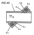
- another ultrasonic flow meter of the present invention includes: a measurement flow path through which a fluid to be measured flows; ultrasonic transducers provided respectively on an upstream side and a downstream side with respect to each other along the measurement flow path; and an upstream aperture hole and a downstream aperture hole, the aperture holes for exposing the ultrasonic transducers to the measurement flow path, wherein at least one of the aperture holes includes a plurality of partitioned paths extending along a propagation direction of the ultrasonic wave.
- the aperture flow path within the aperture hole provided along the side surface of the flow path is divided into small parts, whereby a vortex is less likely to occur and it is possible to reduce the flow of the fluid into the aperture hole. Therefore, it is possible to properly measure the flow rate even when a pulsation occurs.
- At least one of the aperture holes includes a plurality of partitioned paths extending along a propagation direction of the ultrasonic wave.
- the fluid flow into the aperture hole can be reduced by the influent suppressor and the upper limit value for the measurement can be improved.
- the ultrasonic wave propagates through the fluid within the partitioned paths, there is little decrease in the sensitivity.
- the partitioning of the paths it is possible to maintain the rectilinear property of the ultrasonic wave and to realize a desirable transmission/reception thereof.
- the aperture flow path within the aperture hole provided along the side surface of the flow path is divided into small parts, whereby a vortex is less likely to occur and it is possible to further reduce the flow of the fluid into the aperture hole. Therefore, it is possible to properly measure the flow rate even when a pulsation occurs.
- each of the partitioned paths has an inlet surface extending along a vibration surface of the ultrasonic transducer and an outlet surface extending along a wall surface of the measurement flow path.
- each of the partitioned paths of one of the aperture holes extends colinearly with a corresponding one of the partitioned paths of the other aperture hole.
- the transmission surface and the reception surface are aligned with each other along the traveling direction of the ultrasonic wave, whereby it is possible to reduce the reflective attenuation thereof due to the partition plate in the partitioned paths of the opposing aperture hole.
- one side of a vertical section of each of the partitioned paths is longer than a half wavelength of an ultrasonic wave used for transmission/reception.
- the viscosity influence from the partition surface is reduced, whereby it is possible to provide partitioned paths with little attenuation.
- one side of a vertical section of each of the partitioned paths is not an integral multiple of a half wavelength of an ultrasonic wave used for transmission/reception.
- a distance between the partitioned paths of the aperture hole and the vibration surface of a corresponding one of the ultrasonic transducers is an integral multiple of a half wavelength of the ultrasonic wave.
- resonance is provided at the half wavelength, whereby it is possible to provide an efficient radiation.
- a thickness of each partition of the partitioned paths is shorter than the wavelength of an ultrasonic wave used for transmission/reception.
- the partitioned paths are formed by fitting a honeycomb lattice into the aperture hole.
- a lattice it is possible to divide each aperture hole in the vertical and lateral directions.
- one of the partitioned paths has its opening at a center of the aperture hole.
- the aperture hole is aligned with the center of the ultrasonic transducer, thereby allowing for an efficient transmission/reception.
- a path length of each of the partitioned paths is shorter than the wavelength of an ultrasonic wave used for transmission/reception.
- the partitioned paths are formed by arranging a net member in the aperture hole along a direction perpendicular to a propagation direction of the ultrasonic wave.
- a net member in the aperture hole along a direction perpendicular to a propagation direction of the ultrasonic wave.
- each of the partitioned paths includes a communication section at a certain point along its length for communicating the partitioned path with an adjacent one of the partitioned paths.
- FIG 1 is a cross-sectional view illustrating a structure of an ultrasonic flow meter according to Embodiment 1 of the present invention.
- reference numeral 6 is a measurement flow path surrounded by a flow path wall 7
- reference numerals 8 and 9 are upstream and downstream ultrasonic transducers, respectively, attached to the flow path wall 7 via a vibration conduction suppressor 10 so as to oppose each other.
- the upstream ultrasonic transducer 8 and the downstream ultrasonic transducer 9 are spaced from each other by a distance L and inclined by an angle ⁇ with respect to the flow direction of the measurement flow path 6 .
- Reference numerals 11 and 12 are upstream and downstream aperture holes for exposing the ultrasonic transducers 8 and 9 , respectively, to the measurement flow path 6 .
- the aperture holes 11 and 12 are each provided in the form of a depression in the flow path wall 7 .
- Reference numeral 13 is an ultrasonic wave propagation path (indicated by two-dot chain lines) along which an ultrasonic wave transmitted from one of the ultrasonic transducers 8 and 9 opposing each other is propagated directly to the other one of the ultrasonic transducers 8 and 9 without being reflected by the wall surface.
- Reference numeral 14 is a first influent suppressor provided for the upstream aperture hole 11 for reducing the inflow of the fluid to be measured into the upstream aperture hole 11
- reference numeral 15 is a first influent suppressor provided for the downstream aperture hole 12 for reducing the inflow of the fluid to be measured into the downstream aperture hole 12
- Reference numeral 16 is a second influent suppressor provided on the upstream side of the ultrasonic wave propagation path 13 for reducing the inflow of the fluid to be measured into the upstream and downstream aperture holes 11 and 12 .
- the second influent suppressor 16 is fit into a depression 7a provided in the flow path wall 7 .
- Figure 2 illustrates the first influent suppressor 15 provided for the downstream aperture hole 12 .
- Reference numeral 21 is an aperture hole sealing section having many ultrasonically transmissive holes 22 capable of transmitting an ultrasonic wave therethrough.
- the aperture hole sealing section 21 is provided across the ultrasonic wave propagation path 13 so as to cover the aperture hole 12 and extend coplanarly with a measurement flow path surface 6a, thereby preventing the inflow of the fluid to be measured into the aperture hole 12.
- the aperture hole sealing section 21 is a mesh, or the like, having many ultrasonically transmissive holes 22 capable of transmitting an ultrasonic wave therethrough, which is directly provided in a portion of the measurement flow path surface 6a of the measurement flow path 6 corresponding to the aperture hole 12 and is coplanar with the measurement flow path surface 6a so as not to disturb the flow.
- Figure 3 illustrates the first influent suppressor 14 provided for the upstream aperture hole 11 .
- the first influent suppressor 14 protrudes from the flow path wall 7 and includes a flow deflector 14a in the form of a smooth protrusion and a guide surface 14b provided on the upstream side of the flow deflector 14a with smoothly increasing protrusion heights.
- the second influent suppressor 16 has a direction regulation section 16a for adjusting the flow direction of the fluid to be measured and a variation suppressing section 16b for making the flow velocity distribution uniform or reducing the pulsation of the flow.
- the direction regulation section 16a includes partition walls for dividing the cross section of the measurement flow path 6 into small portions.
- the variation suppressing section 16b has a small length along the flow direction and has many minute communication paths along the cross section of the measurement flow path 6 .
- Reference numeral 17 is an upstream elbow section which communicates with a control valve (not shown) provided on the upstream side along the measurement flow path 6
- reference numeral 18 is a downstream elbow section which communicates with an outlet (not shown) provided on the downstream side along the measurement flow path 6 .
- the flow path is provided in a compact structure.
- Reference numeral 19 is a measurement control section connected to the ultrasonic transducers 8 and 9 for effecting the transmission and reception of an ultrasonic wave
- reference numeral 20 is a calculation section for calculating the flow velocity based on a signal from the measurement control section 19 so as to calculate the flow rate.
- the flow rate measurement operation using an ultrasonic wave will be described.
- an ultrasonic wave is transmitted and received between the ultrasonic transducers 8 and 9 across the measurement flow path 6 by the function of the measurement control section 19.
- the propagation time T1 the amount of time required for an ultrasonic wave emitted from the upstream ultrasonic transducer 8 to be received by the downstream ultrasonic transducer 9 .
- the propagation time T2 the amount of time required for an ultrasonic wave emitted from the downstream ultrasonic transducer 9 to be received by the upstream ultrasonic transducer 8 , is also measured.
- the flow rate is calculated by the calculation section 20 based on the measured propagation times T1 and T2 according to the expressions shown below.
- the flow velocity V is calculated based on the following expressions.
- T1 L/(C+Vcos ⁇ )
- T2 L/(C-Vcos ⁇ )
- the flow velocity V can be calculated from the values of T1 and T2.
- K is a correction coefficient which is determined in view of the flow velocity distribution across the transverse-sectional area S.
- the flow rate is obtained by the calculation section 20 .
- the fluid to be measured enters the measurement flow path 6 with a non-uniform flow or a flow pulsation due to the increase/decrease in the flow path cross-sectional area provided by the control valve (not shown) which is provided on the upstream side of the measurement flow path 6 or due to the passage through the elbow section 17.
- the flow in the measurement flow path 6 is rectified and the flow disturbance is reduced by the direction regulation section 16a of the second influent suppressor 16 provided on the upstream side of the ultrasonic wave propagation path 13 to a direction such that the fluid does not easily flow into the aperture holes 11 and 12 , while disturbances from variations in the flow due to a pulsating flow, or the like, are reduced by the variation suppressing section 16b so as to further suppress the fluid flow into the aperture holes 11 and 12 . Then, the flow enters the ultrasonic wave propagation path 13 .
- the variation suppressing section 16b may be a meshed member, a foamed member, a microporous plate, a non-woven fabric, or the like, with a large aperture ratio, which can be provided to have a small thickness along the flow direction.
- the variation suppressing section 16b may be a meshed member, a foamed member, a microporous plate, a non-woven fabric, or the like, with a large aperture ratio, which can be provided to have a small thickness along the flow direction.
- the aperture hole sealing section 21 such as a mesh having many ultrasonically transmissive holes 22 capable of transmitting an ultrasonic wave therethrough is provided along the measurement flow path surface 6a of the measurement flow path 6 for the flow rectified by the second influent suppressor 16 to be coplanar with the measurement flow path surface 6a so as not to disturb the flow.
- the first influent suppressor 14 is formed by the flow deflector 14a in the form of a protrusion provided near and on the upstream side of the aperture hole 11 so as to further reduce the flow of the fluid into the aperture hole 11 as indicated by arrows in Figure 3 , thereby reducing flow disturbances such as vortices and stabilizing the flow.
- the upstream aperture hole 11 extends in a direction at an obtuse angle with respect to the measurement flow path 6 , the intensity of any vortex is smaller than that for the downstream aperture hole 12 .
- the adverse influence thereof is small, and it may not be necessary to provide the first influent suppressor 14 .
- the first influent suppressor 14 may be formed integrally with the flow path wall 7 so as to simplify the structure and reduce the cost.
- the ultrasonic waves are transmitted and received between the ultrasonic transducers 8 and 9 along the ultrasonic wave propagation path 13 where the flow is stabilized.
- the ultrasonic reception level can be improved by the stabilization of the flow, it is possible to reduce the power consumption for the transmission of an ultrasonic wave.
- the aperture hole sealing section 21 is provided only for the downstream aperture hole 12 , it is possible to reduce the amount of attenuation of the ultrasonic wave through the aperture hole sealing section 21 and to reduce the power consumption by the reduction in the driving power input for the ultrasonic transducers 8 and 9 .
- an electric cell is used for driving the device such as a gas meter for household use, it is possible to continuously use the meter with only a small electric cell capacity over a long period of time.
- FIG 4 is a cross-sectional view of an ultrasonic flow meter illustrating an alternative first influent suppressor.
- an aperture hole sealing section 21a having the ultrasonically transmissive holes 22 as those of the embodiment of Figure 1 is provided as the first influent suppressor 15 .
- an aperture hole sealing section 21b having the ultrasonically transmissive holes 22 is provided as the first influent suppressor 14 . Both of the aperture hole sealing sections 21a and 21b are provided coplanarly with the measurement flow path surface.
- the aperture hole sealing sections 21a and 21b for both of the upstream aperture hole 11 and the downstream aperture hole 12 , respectively, it is possible to suppress the inflow of the fluid into the aperture holes so as to prevent vortices or flow disturbances, thereby improving the measurement precision, as well as to realize a measurement with an increased precision even for a pulsating flow with a momentary reverse flow.
- the flow disturbance in the aperture holes 11 and 12 can be significantly reduced, it is possible to reduce the refraction and/or reflection of the ultrasonic waves due to any disturbances, thereby realizing transmission and reception of the ultrasonic waves with desirable S/N characteristics, and to reduce the transmission output, thereby reducing the driving input and thus the power consumption.
- the aperture hole sealing sections 21a and 21b will be described without reference to a figure. Since the upstream aperture hole 11 extends in a direction at an obtuse angle with respect to the measurement flow path 6 , the intensity of the vortex is smaller. Therefore, the influent suppression effect can be expected even if the aperture ratio of the aperture hole sealing section 21b provided in the upstream aperture hole 11 is greater than the aperture ratio of the aperture hole sealing section 21a provided in the downstream aperture hole 12 . Thus, in this embodiment, the upstream aperture hole sealing section 21b has an aperture ratio greater than that of the downstream aperture hole sealing section 21a .
- Figure 5 illustrates another embodiment of the first influent suppressor 15 provided for the downstream aperture hole 12 .
- Reference numeral 23 is a flow deflector provided near and on the upstream side of the downstream aperture hole 12 including the aperture hole sealing section 21 .
- the flow deflector 23 is provided in the form of a plate or a blade and regulates the flow direction so that the fluid to be measured dose not flow into the aperture hole 12 .
- the aperture hole 12 is provided with both the aperture hole sealing section 21 and the flow deflector 23 as the first influent suppressor 15 .
- the flow direction is regulated by the flow deflector 23 so as to reduce the amount of flow directed to the downstream aperture hole 12 . Even if there is a slight amount of flow directed to the downstream aperture hole 12 , the flow is prevented by the aperture hole sealing section 21 from flowing into the aperture hole 12 so as to prevent flow disturbances such as vortices in the aperture hole 12 and thus stabilize the flow in the ultrasonic wave propagation path 13 , thereby further improving the measurement precision. Moreover, since the amount of flow hitting the aperture hole sealing section 21 can be reduced by the flow deflector 23 , even when fine particle foreign matter such as dust is included in the fluid to be measured, it is possible to reduce the attachment of the foreign matter onto the aperture hole sealing section 21 .
- the specification of the aperture hole sealing section 21 can be selected primarily in view of the ultrasonic transmissivity, thereby improving the freedom in the selection or setting thereof. Moreover, it is possible to further increase the ultrasonic transmissivity to increase the sensitivity, thereby reducing the power consumption or increasing the precision. A similar structure can be employed for the upstream aperture hole 11 so as to further improve the measurement precision.
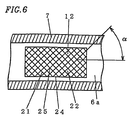
- Figure 6 illustrates another embodiment of the aperture hole sealing section.
- Reference numeral 24 is a meshed member having the ultrasonically transmissive holes 22 arranged in a meshed pattern.
- the meshed member 24 is provided along the measurement flow path surface 6a over the aperture hole 12 as the aperture hole sealing section 21 .
- the flow direction of the fluid to be measured along the measurement flow path 6 is substantially horizontal and the measurement flow path surface 6a along which the aperture holes 11 and 12 are provided is substantially vertical.
- the meshed member 24 is formed by inclined mesh portions 25 having an angle of ⁇ with respect to the horizontal direction such that there is no mesh portion arranged along the horizontal direction.
- Figure 7 is a cross-sectional view illustrating the measurement flow path shown in Figure 1 taken along line A-A.
- the cross section of the measurement flow path 6 along a direction perpendicular to the flow has a rectangular shape with a width W along the sides on which the ultrasonic transducers 8 and 9 are arranged to oppose each other, and with a height H.
- the measurement flow path 6 is formed by the flow path wall 7 which is obtained by mating a flow path wall 7b having a depression and a flow path wall 7c having a protrusion with each other.
- the rectangular cross section as used herein also includes a generally rectangular shape with a rounded portion (corner R) in each corner of the rectangular cross section so as to ensure the durability of the manufacturing equipment such as a metallic die used in the case where the flow path wall 7 is formed by die casting.
- Figure 8 illustrates the aperture shape of the aperture hole 12 provided along the measurement flow path surface 6a of the measurement flow path 6 shown in Figure 7 having the rectangular cross section.
- the aperture shape of the aperture hole 12 along the measurement flow path surface 6a has a rectangular shape with a side 12a extending in a direction substantially perpendicular to the flow direction (indicated by an arrow in the figure) through the measurement flow path 6 and a side 12b extending in a direction substantially parallel to the flow direction.
- the aperture hole 12 has a constant length as indicated by D in the figure along the flow direction for any height H, whereby it is possible to equally transmit and receive an ultrasonic wave with respect to the height direction H and thus to effect an equal measurement across the measurement flow path 6 , thereby realizing a high-precision measurement.
- the length D of such an aperture hole along the flow direction is shorter than that which results when the aperture hole has a circular shape or a shape with an arc portion of the same area, whereby it is possible to further reduce flow disturbances in the measurement flow path 6 and/or the fluid flow into the aperture hole 12 , thereby improving the measurement precision. While the above description has been directed to the downstream aperture hole 12 , it is understood that the aperture shape of the upstream aperture hole 11 along the measurement flow path surface 6a may also be rectangular so as to further improve the measurement precision.
- the inflow of the fluid to be measured into the aperture hole 12 is reduced by the first influent suppressor 15 provided at least for the downstream aperture hole, whereby it is possible to significantly reduce flow disturbances between the ultrasonic transducers 8 and 9 , thereby increasing the measurement precision and the upper limit value for the flow rate measurement.
- the first influent suppressor 15 may be the aperture hole sealing section 21 having the ultrasonically transmissive holes 22 so as to further increase the effect of suppressing the flow of the fluid to be measured into the aperture hole, thereby stabilizing the flow in the aperture hole.
- the aperture hole sealing section 21 can be provided only for the downstream aperture hole 12 so as to further reduce the attenuation of the ultrasonic wave, thereby reducing the driving input for the ultrasonic transducers and the power consumption, and improving the measurement precision.
- the first influent suppressor 14 provided for the upstream aperture hole 11 includes the aperture hole sealing section 21b having the ultrasonically transmissive holes 22 .
- the aperture ratio of the aperture hole sealing section 21b provided for the upstream aperture hole 11 is greater than the aperture ratio of the aperture hole sealing section 21 a provided for the downstream aperture hole 12 .
- the first influent suppressor 15 includes the aperture hole sealing section 21 having the ultrasonically transmissive holes 22 and the flow deflector provided in the vicinity of the aperture hole 11 or 12 .
- the aperture hole sealing section can be selected primarily in view of the ultrasonic transmissivity without so much concern about the clogging of the aperture hole sealing section, thereby increasing the freedom of the selection.
- the aperture hole sealing section 21 is a meshed member 24 of an inclined mesh pattern having an inclination with respect to the horizontal direction.
- the pattern is inclined with respect to the horizontal direction, so that it is possible to facilitate settling of minute particles such as dust attached onto the inclined mesh portions 25 , thereby reducing the amount of such minute particles deposited and thus preventing clogging of the meshed member. Therefore, it is possible to ensure propagation of the ultrasonic wave therethrough and to maintain a stable measurement precision over a long time, thereby improving the durability and reliability.
- the cross section of the measurement flow path 6 along a direction perpendicular to the flow therethrough has a rectangular shape.
- the rectangular cross section it is possible to increase the measurement area with respect to the total measurement cross-sectional area, thereby allowing for a flow measurement under the same condition from the upstream side to the downstream side of the ultrasonic wave propagation path 13 .
- it is possible to increase the two-dimensionality of the flow along the measurement flow path 6 thereby allowing for a high precision measurement of the average flow velocity of the fluid.
- Each of the aperture holes 11 and 12 opens into the measurement flow path 6 in a shape which has a side extending along a direction substantially perpendicular to the direction of the flow through the measurement flow path 6 .
- elbow sections 17 and 18 are bent in the width W direction of the measurement flow path 6 .
- the elbow sections 17 and 18 may alternatively be bent in the height H direction of the measurement flow path 6 or any other direction, and the elbow sections 17 and 18 may be bent at different angles.
- the effect of suppressing the inflow of the fluid into the aperture hole has been described as the function of the first influent suppressors 14 and 15 .
- the first influent suppressors 14 and 15 are also expected to have an entrainment suppressing effect to suppress vortices which are generated when the fluid in the aperture hole is entrained by the fluid flowing through the measurement flow path due to the viscosity thereof.
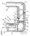
- Figure 9 is a cross-sectional view illustrating a structure of an ultrasonic flow meter according to Embodiment 2 of the present invention.
- like elements and functions to those of the embodiment shown in Figures 1 to 8 are provided with like reference numerals and will not be described in detail, and the parts which are different from the above embodiment will be focused on in the following description.
- Reference numeral 26 is a non-uniform flow suppressor provided in an introduction section 27 , which is an inlet of the measurement flow path 6 , and having many minute passage openings 26a .
- the non-uniform flow suppressor 26 equalizes the flow velocity distribution when the fluid flowing into the introduction section 27 has a deviation in its flow velocity distribution, before the fluid is supplied to the measurement flow path 6 .
- Reference numeral 28 is a valve block connected on the upstream side of the elbow section 17 and having a connection port 29 which is opened to the introduction section 27 .
- the valve block 28 is provided with a control valve 32 having a valve seat 30 and a valve element 31 opposing the valve seat 30 .
- Reference numeral 33 is a fluid inlet provided on the upstream side of the valve seat 30 through which the fluid flows in.
- Reference numeral 34 is an outlet block connected to the downstream side of the elbow section 18 and having a fluid outlet 35 through which the fluid flows out.
- Reference numeral 36 is a spring for biasing the valve element 31 toward the valve seat 30
- reference numeral 37 is a driving section such as a solenoid or a motor for driving the valve element 31 to open or close the control valve 32 .
- the control valve 32 When the control valve 32 is opened, the fluid to be measured flows in through the fluid inlet 33 , passes through the valve seat 30 and the connection port 29 , and flows into the introduction section 27 .
- the fluid flowing into the introduction section 27 has a reduced uniformity in the flow direction and/or the flow velocity distribution and has irregularity such as pulsation due to the influence of the piping configuration upstream of the fluid inlet 33 and/or the passage through the bent path through the valve block 28.
- the non-uniformity in the flow direction and/or the flow velocity distribution is improved and the pulsation of the flow is reduced, thereby providing a stable flow flowing into the measurement flow path 6 .
- the flow velocity distribution of the fluid across the cross section of the measurement flow path 6 is equalized by the direction regulation section 16a of the second influent suppressor 16 , and the flow is rectified in a direction such that the fluid is less likely to flow into the aperture holes 11 and 12 , while the flow variation such a pulsation is further reduced by the variation suppressing section 16b .
- the fluid flows into the ultrasonic wave propagation path 13 .
- the first influent suppressors 14 and 15 are provided near and on the upstream side of the upstream and downstream aperture holes 11 and 12 , respectively, so as to reduce the flow of the fluid into the aperture holes 11 and 12 .
- it is possible to further increase the upper limit value for the flow rate measurement by reducing the attenuation of the ultrasonic wave due to the variation in the flow.
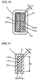
- Figure 10 is a plan view illustrating the introduction section 27 .
- the non-uniform flow suppressor 26 is provided across the entire area of the introduction section 27 .
- Reference numeral 29a denotes a first aperture position (indicated by a two-dot chain line) of the connection port 29 in the case where the control valve 32 is provided along the left-right direction of the figure as shown in Figure 9 with the connection port 29 being provided on the left side of the figure
- reference numeral 29b denotes a second aperture position (indicated by a two-dot chain line) of the connection port 29 in the case where the control valve 32 is provided along the front-back direction of Figure 9 with the connection port 29 being provided on the reverse side of the figure.
- the cross-sectional area Sa of the introduction section 27 is set to be greater than the cross-sectional area Sb of the measurement flow path 6 defined by a rectangular shape having the width W and the height H (see Figure 11 ) (Sa>Sb), thereby increasing the installment area for the non-uniform flow suppressor 26 so that the first aperture position 29a and the second aperture position 29b can be both arranged in the introduction section 27 .
- it is possible to reduce the loss in the pressure of the fluid to be measured due to the non-uniform flow suppressor 26 .
- first and second aperture positions 29a and 29b have a positional deviation with respect to the introduction section 27 for various arrangements/configurations of the valve block 28 , it is possible to equalize the flow distribution by the minute passage openings 26a of the non-uniform flow suppressor 26 before the fluid flows into the measurement flow path 6 . Therefore, it is possible to ensure the measurement precision for the variation in the flow path configuration and/or the piping configuration upstream of the measurement flow path 6 , e.g., the valve block 28 , whereby it is possible to improve the freedom in the installment.
- the aperture dimension Ta of the passage openings 26a of the non-uniform flow suppressor 26 each having a minute aperture is set to be less than the aperture dimension Tb of passage openings 16c of the variation suppressing section 16b of the second influent suppressor 16 each having a minute aperture (Ta ⁇ Tb).
- the non-uniform flow suppressor 26 can have a greater function of equalizing the flow pulsation or the deviation in the flow velocity distribution than that of the second influent suppressor 16 . Therefore, by providing the non-uniform flow suppressor 26 , it is possible to supply a more stabilized flow into the measurement flow path 6 .
- connection port 29 through which the fluid flows in from the upstream side is positionally deviated, it is possible to perform a measurement with an increased precision by supplying the fluid into the measurement flow path 6 in a more equalized manner. Even when the incoming fluid has a pulsation, it is possible to supply a flow with a reduced pulsation so that it is possible to improve the measurement precision even for a pulsating flow.
- the aperture dimension of the passage openings 26a of the non-uniform flow suppressor 26 is set to be smaller than that of the passage openings 16c of the variation suppressing section 16b of the second influent suppressor 16 , whereby it is possible to reduce the amount of foreign matter such as dirt or dust entering the measurement flow path 6 so as to ensure a proper measurement operation and to increase the reliability.
- the cross-sectional area Sa of the non-uniform flow suppressor 26 is set to be greater than the cross-sectional area Sb of the measurement flow path 6 , whereby it is possible to reduce the loss in the pressure of the fluid to be measured and to prevent deterioration of the measurement characteristics even when the foreign matter is attached onto the non-uniform flow suppressor 26 .
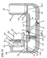
- Figure 12 illustrates an alternative embodiment of the non-uniform flow suppressor 26 .
- a first non-uniform flow suppressor 26b is provided in the introduction section 27, and a second non-uniform flow suppressor 26c is provided in an exit section 38 on the downstream side of the measurement flow path 6.
- the second non-uniform flow suppressor 26c includes many minute passage openings 26d as the first non-uniform flow suppressor 26b.
- the second non-uniform flow suppressor 26c provides the effect of reducing the pulsation and the effect of suppressing the non-uniform flow.
- the second non-uniform flow suppressor 26c provides the effect of reducing the pulsation and the effect of suppressing the non-uniform flow.
- the aperture dimension of the passage openings 26d of the second non-uniform flow suppressor 26c can be set to be less than that of the passage openings 16c of the second influent suppressor 16 , and/or the cross-sectional area of the exit section 38 where the second non-uniform flow suppressor 26c is provided can be set to be greater than that of the measurement flow path 6 so as to provide the above-described effects as with the introduction section 27 .
- the non-uniform flow suppressor 26 including the passage openings 26a each having a minute aperture is provided in the introduction section 27 provided on the upstream side of the measurement flow path 6 .
- the introduction section 27 provided on the upstream side of the measurement flow path 6 .
- the non-uniform flow suppressors 26b and 26c having the passage openings 26a and 26d each having a minute aperture are provided in the introduction section 27 provided on the upstream side of the measurement flow path 6 and in the exit section 38 on the downstream side of the measurement flow path 6 , respectively.
- the cross-sectional area of the introduction section 27 or the exit section 38 can be set to be greater than that of the measurement flow path 6 .
- the aperture size of the passage opening of the non-uniform flow suppressor 26 is less than the aperture size of the passage opening provided in the second influent suppressor 16 .
- elbow sections 17 and 18 are bent in the width W direction of the measurement flow path 6 has been illustrated in the present embodiment. However, it is understood that the elbow sections 17 and 18 may alternatively be bent in the height H direction of the measurement flow path 6 or any other direction, and the elbow sections 17 and 18 may be bent at different angles.
- Figure 13 is a cross-sectional view illustrating a structure of an ultrasonic flow meter according to Embodiment 3 of the present invention.
- like elements and functions to those of the embodiments shown in Figures 1 to 12 are provided with like reference numerals and will not be described in detail, and the parts which are different from the above embodiments will be focused on in the following description.
- Reference numeral 39 is a first influent suppressor for reducing the inflow of the fluid to be measured into the aperture hole 11 irrespective of whether the fluid to be measured is flowing in the forward direction or in the reverse direction along the measurement flow path 6 .
- the first influent suppressor 39 includes a flow deflector 40a provided near and on the upstream side of the aperture hole 11 and a flow deflector 40b provided near and on the downstream side of the aperture hole 11 .
- Reference numeral 41 is a second influent suppressor provided on the downstream side of the ultrasonic wave propagation path 13 .
- the second influent suppressor 41 includes a direction regulation section 41a for adjusting the flow direction of the fluid to be measured and a variation suppressing section 41b for making the flow velocity distribution uniform or reducing the pulsation of the flow.
- a reverse flow may enter the measurement flow path 6 .
- the first influent suppressor 15 or 39 or the second influent suppressor 41 can function for such a reverse flow as for a forward flow to prevent the flow from entering the aperture holes 11 and 12 . Therefore, even when a pulsating flow causes a momentary reverse flow, it is possible to reduce the inflow of the fluid to be measured into the aperture hole as for a forward flow and to significantly reduce flow disturbances between the ultrasonic transducers 8 and 9 , thereby increasing the measurement precision and the upper limit value for the flow rate measurement. Moreover, it is possible to perform a measurement with an increased precision even for a reverse flow, and to increase the freedom of the installment, thereby improving the convenience.
- the first influent suppressor 39 includes the protrusions of the flow deflectors 40a and 40b provided along the surface in which the aperture hole 11 is opened near and on the upstream side of the aperture hole 11 and near and on the downstream side of the aperture hole 11 , respectively, has been described above.
- the protrusions may be provided to surround the circumference of the aperture hole 11 and/or the aperture hole 12 (not shown).
- the first influent suppressor 39 can be provided by using the aperture hole sealing section described above with reference to Figure 2 or 5 , so as to improve the measurement precision even for a strong reverse flow and to increase the convenience.
- Figure 14 illustrates an alternative embodiment of the first influent suppressor.
- Reference numeral 23 is a flow deflector provided near and on the upstream side of the aperture hole 12 including the aperture hole sealing section 21
- reference numeral 42 is a flow deflector provided near and on the downstream side of the aperture hole 12 .
- Each of the flow deflectors 23 and 42 is provided in the form of a plate or a blade and regulates the flow direction so that the fluid to be measured does not flow into the aperture hole 12 .
- the first influent suppressor includes the aperture hole sealing section 21 and the flow deflectors 23 and 42 which are provided upstream and downstream, respectively, of the aperture hole 11 and/or the aperture hole 12 .
- the flow direction is regulated by the flow deflector 23 provided on the upstream side of the aperture hole 12 so as to reduce the amount of flow directed into the aperture hole 12 .
- the flow direction is regulated by the flow deflector 42 provided on the downstream side of the aperture hole 12 so as to reduce the amount of flow directed into the aperture hole 12 .
- the specification of the aperture hole sealing section 21 can be selected primarily in view of the ultrasonic transmissivity, thereby improving the freedom in the selection or setting thereof. Moreover, it is possible to further increase the ultrasonic transmissivity to increase the sensitivity, thereby reducing the power consumption or increasing the precision.
- the aperture hole sealing section 21 and the flow deflectors 23 and 42 can be provided also for the upstream aperture hole 11 as for the downstream aperture hole 12 so as to provide a similar effect for the aperture hole 11 . Moreover, it is possible to further improve the measurement precision for a reverse flow, whereby it is possible to increase the ultrasonic transmissivity so as to increase the sensitivity and to reduce the power consumption or to increase the measurement precision.
- the ultrasonic flow meter according to Embodiment 3 of the present invention even when the flow has a pulsation and causes a momentary reverse flow, it is possible to reduce, as in the case of a forward flow, the inflow of the fluid to be measured into the aperture hole, and to significantly reduce flow disturbances between the ultrasonic transducers, thereby increasing the measurement precision and the upper limit value for the flow rate measurement. Moreover, it is possible to perform a measurement with an increased precision even for a reverse flow, and to increase the freedom of the installment, thereby improving the convenience.
- the flow deflector is provided on the upstream side and the downstream side of the aperture hole.
- elbow sections 17 and 18 are bent in the width W direction of the measurement flow path 6 has been illustrated in the present embodiment. However, it is understood that the elbow sections 17 and 18 may alternatively be bent in the height H direction of the measurement flow path 6 or any other direction, and the elbow sections 17 and 18 may be bent at different angles.
- Figure 15 is a cross-sectional view illustrating a structure of an ultrasonic flow meter according to Embodiment 4 of the present invention.
- like elements and functions to those of the embodiments shown in Figures 1 to 14 are provided with like reference numerals and will not be described in detail, and the parts which are different from the above embodiments will be focused on in the following description.
- Reference numeral 43 is a propagation path flow regulator provided on the upstream side of the ultrasonic wave propagation path 13 .
- the propagation path flow regulator 43 is arranged substantially parallel to the ultrasonic wave propagation path 13 which extends diagonally across the measurement flow path 6 and is spaced slightly apart from the ultrasonic wave propagation path 13 so as not to interfere with the propagation of the ultrasonic wave.
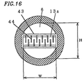
- Figure 16 illustrates the propagation path flow regulator 43 as viewed along the direction of the flow through the measurement flow path 6 .
- the propagation path flow regulator 43 is arranged in the measurement flow path 6 which has a circular transverse cross section.
- Reference numeral 13a is an ultrasonic wave propagation path as shown in the cross-sectional view of the measurement flow path 6 taken along the direction normal to the paper of Figure 15 (the height direction of the measurement flow path 6 ).
- the propagation path flow regulator 43 has a width along the height direction greater than the width of the ultrasonic wave propagation path 13a along the height direction which is indicated by a two-dot chain line, and has many regulation sections 44 which are exposed to the flow.
- the fluid to be measured enters the measurement flow path 6 with a non-uniform flow or a flow pulsation due to the increase/decrease in the flow path cross-sectional area provided by the control valve (not shown) which is provided on the upstream side of the measurement flow path 6 or due to the passage through the elbow section 17 . Then, the disturbance of the flow is facilitated by the regulation sections 44 of the propagation path flow regulator 43 provided immediately upstream of the ultrasonic wave propagation path 13 .
- the propagation path flow regulator 43 is provided immediately upstream of the ultrasonic wave propagation path 13 to extend all the way from the vicinity of the upstream ultrasonic transducer 8 to the vicinity of the downstream ultrasonic transducer 9 , whereby the flow disturbance is equally facilitated across the entire area of the ultrasonic wave propagation path 13 . In this way, the variation in the flow condition is reduced in the ultrasonic wave propagation path 13 from the upstream side to the downstream side so as to facilitate the measurement of the average flow velocity in the ultrasonic wave propagation path 13 .
- the flow disturbance is facilitated by the propagation path flow regulator 43 in the ultrasonic wave propagation path 13 .
- the difference between this flow disturbance and the flow disturbance which results in the ultrasonic wave propagation path 13 when the flow velocity is large (when the flow rate is large), and thus the fluid flows into the measurement flow path 6 as a disturbed flow is small. Therefore, it is possible to stably disturb the flow in the ultrasonic wave propagation path 13 over a wide flow rate range from a small flow rate to a large flow rate.
- the propagation path flow regulator 43 is arranged to extend diagonally across the measurement flow path 6 , whereby the propagation path flow regulator 43 can have a greater length within the measurement flow path 6 than that obtained when the propagation path flow regulator 43 is arranged to extend orthogonal to the measurement flow path 6. Therefore, it is possible to provide the propagation path flow regulator 43 with a large aperture ratio and to realize a measurement device with a reduced pressure loss.
- the flow velocity V is obtained based on the ultrasonic propagation times T1 and T2, as described above, and the flow rate is obtained from the cross-sectional area S of the measurement flow path 6 and the correction coefficient K.
- the correction coefficient K substantially changes in the transitional zone where the flow rate zone transitions from the laminar flow zone to the disturbed flow zone as illustrated in Figure 17 in the absence of the propagation path flow regulator 43 extending along the ultrasonic wave propagation path 13 .
- the correction coefficient K substantially changes, i.e., by ⁇ K1, thereby resulting in an increased flow rate measurement error.
- This error may occur from a variation in the flow condition caused by the variation in the Reynolds number which is due to the change in the kinematic viscosity occurring from the change in temperature of the fluid or the composition ratio of the fluid.
- a fluid such as town gas or LPG (liquefied petroleum gas) where there may be a variation in the gas composition due to a seasonal or regional variation, this error needs to be taken into consideration.
- the propagation path flow regulator 43 is provided along the ultrasonic wave propagation path 13 , as in the present embodiment, it is possible to reduce the difference between the correction coefficient K in the laminar flow zone where the flow velocity is small and that in the disturbed flow zone, as illustrated in Figure 18 , because the fluid can be equally disturbed in the ultrasonic wave propagation path 13 from the upstream side to the downstream side. Moreover, the change in the correction coefficient is also small in the transitional zone where the flow transitions from a laminar flow to a disturbed flow. Thus, the correction coefficient is averaged.
- the change in the correction coefficient can be sufficiently small, i.e., ⁇ K2 (K2 ⁇ K1), thereby allowing for a measurement with an increased measurement precision.
- ⁇ K2 K2 ⁇ K1
- This is advantageous when there is a change in the temperature or a change in the composition of the fluid.
- it is possible to realize a measurement with a further increased precision particularly when measuring the flow rate of a fuel gas such as town gas or LPG for which such a change in the composition and a change in the temperature are expected.
- propagation path flow regulator 43 is arranged to extend only over a portion of the circular cross section of the measurement flow path 6 corresponding to the ultrasonic wave propagation path 13 , it is understood that the propagation path flow regulator 43 may alternatively be provided to extend across the height H direction of the cross section to facilitate the stabilization of the correction coefficient K.
- the outlet side 43b of the propagation path flow regulator 43 is arranged to extend substantially parallel to the ultrasonic wave propagation path 13 in the present embodiment, it is understood that the propagation path flow regulator 43 may be provided in any other arrangement as long as it is provided at a substantially equal position with respect to the width W direction of the measurement flow path 6 from the upstream end to the downstream end of the ultrasonic wave propagation path 13 , and that the propagation path flow regulator 43 may have some depression or protrusion along the outlet side 43b .
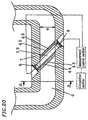
- Figure 20 illustrates the structure of the ultrasonic flow meter illustrating an alternative embodiment of the propagation path flow regulator.
- like elements and functions to those of the embodiments shown in Figures 1 to 19 are provided with like reference numerals and will not be described in detail, and the parts which are different from the above embodiments will be focused on in the following description.
- Reference numeral 45 is a propagation path flow regulator provided on the downstream side of the ultrasonic wave propagation path 13 .
- the downstream propagation path flow regulator 45 is arranged substantially parallel to the ultrasonic wave propagation path 13 which extends diagonally across the measurement flow path 6 and is spaced slightly apart from the ultrasonic wave propagation path 13 so as not to interfere with the propagation of the ultrasonic wave.
- Reference numeral 46 is a regulation section provided in the downstream propagation path flow regulator 45 and exposed to the flow.
- the ultrasonic wave propagation path 13 is surrounded by the upstream propagation path flow regulator 43 and the downstream propagation path flow regulator 45 .
- the flow disturbance is equally facilitated across the width W direction in the ultrasonic wave propagation path 13 by the regulation sections 44 of the propagation path flow regulator 43 provided immediately upstream of the ultrasonic wave propagation path 13 across the width W direction of the measurement flow path 6 .
- the downstream propagation path flow regulator 45 which surrounds the ultrasonic wave propagation path 13 together with the upstream propagation path flow regulator 43 so as to apply a back pressure to the flow in the ultrasonic wave propagation path 13 .
- the influence of a pulsation, or the like, which occurs due to variations in the downstream piping configuration or due to the conditions under which the fluid to be measured is used, on the flow condition in the ultrasonic wave propagation path 13 can be reduced so that it is possible to perform a stable flow rate measurement. Even when a reverse flow occurs, it is possible to maintain a stable correction coefficient and to improve the measurement precision.
- Figure 21 is a perspective view illustrating a propagation path flow regulator 47 obtained by integrating together the upstream propagation path flow regulator 43 and the downstream propagation path flow regulator 45 .
- Reference numeral 48 is a connecting section for connecting and integrating together the upstream propagation path flow regulator 43 and the downstream propagation path flow regulator 45
- reference numeral 49 is an ultrasonic transmission window having an aperture opened therein so as not to interfere with the ultrasonic transmission.
- the propagation path flow regulator 47 is connected and integrated together by the connecting section 48, whereby it is possible to prevent the positional shift of the upstream regulation sections 44 and the downstream regulation sections 46 with respect to each other. Thus, it is possible to stabilize the flow by reducing the variation in flow conditions in the ultrasonic wave propagation path 13 , thereby realizing a measurement with little variation.
- the propagation path flow regulator 47 can be structurally reinforced by the connecting section 48 , whereby it is possible to reduce the thickness or the size of each of the propagation path flow regulators 43 and 45 , including the regulation sections 44 and 46 . Thus, it is possible to equalize the flow conditions in the ultrasonic wave propagation path 13 irrespective of the position across the cross section of the measurement flow path 6 .
- the reduction in the thickness or the size of the regulation sections 44 and 46 it is possible to increase the aperture area through which the fluid to be measured flows, whereby it is possible to reduce the loss of pressure in the measurement flow path.
- the propagation path flow regulators 43 and 45 are reinforced by the connecting section 48 , it is possible to prevent deformation over a long term use, thereby improving the durability and the reliability. While a case where the connecting section 48 is arranged to extend between the corners of the propagation path flow regulator 47 has been illustrated above, it is understood that the connecting section 48 may be provided in any other position suitable for the reinforcement as long as it does not interfere with the ultrasonic propagation.
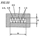
- Figure 22 is a cross-sectional view illustrating an alternative cross section of the measurement flow path 6 according to Embodiment 4 taken along line A-A.
- Reference numeral 50 is a flow path wall defining the measurement flow path 6 which has a rectangular cross section with a width of W and a height of H.
- the regulation sections 44 and 46 are arranged across the rectangular cross section.
- the ultrasonic wave propagation path 13 extends across the width W direction of the ultrasonic wave propagation path 13 , and it is thus possible to increase the ratio of the measurement area with respect to the height H direction of the rectangular cross section.
- the ratio of the measurement area along the height H direction can be constant across the width W direction from the upstream side to the downstream side. Therefore, it is possible to perform a high-precision measurement of the average flow velocity of the fluid in the ultrasonic wave propagation path 13 .
- the flow disturbance is equally facilitated by the regulation sections 44 and 46 of the propagation path flow regulators 43 and 45 from the upstream side to the downstream side over a wide flow rate range, whereby it is possible to measure the average flow velocity with a high precision.
- the height H can be determined in order to reduce the influence of the ultrasonic wave reflected by the upper and lower surfaces which together define the height H of the cross-section.
- the rectangular cross section as used herein also includes a generally rectangular shape with a rounded portion (corner R) in each corner of the rectangular cross section so as to ensure the durability of the manufacturing equipment such as a metallic die used in the case where the flow path wall 7 is formed by die casting.
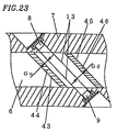
- Figure 23 illustrates the distance between the propagation path flow regulator 43 or 45 and the ultrasonic wave propagation path 13 in the present embodiment.
- the distance between the upstream propagation path flow regulator 43 and the ultrasonic wave propagation path 13 is Gu
- the distance between the downstream propagation path flow regulator 45 and the ultrasonic wave propagation path 13 is Gd.
- the distance between the propagation path flow regulator 43 or 45 and the ultrasonic wave propagation path 13 is optimized so as to stabilize the correction coefficient for the measurement values for a variety of fluids to be measured over a wide flow rate range, thereby equally disturbing the flow distribution in the ultrasonic wave propagation path 13 from the upstream side to the downstream side.
- the Reynolds number is small, the distance Gu and/or Gd can be reduced, and when the Reynolds number is large, distance Gu and/or Gd can be increased.
- the Reynolds number is proportional to the inverse of the kinematic viscosity. Therefore, the distance Gu and/or Gd is increased for a fluid having a small viscosity, and the distance Gu and/or Gd is reduced for a fluid having a large viscosity.
- propane gas has a kinematic viscosity of 4.5 mm 2 /s (300°K)
- methane gas has a kinematic viscosity of 17.1 mm 2 /s (300°K). Therefore, the distance Gu and/or Gd is increased for propane gas, and the distance Gu and/or Gd is reduced for methane gas.
- the propagation path flow regulator 43 or 45 should be provided at a distance as great as possible from the ultrasonic wave propagation path 13 in order to reduce the amount of ultrasonic waves propagating through the ultrasonic wave propagation path 13 and reflected by the propagation path flow regulator 43 or 45 thereby influencing the flow velocity measurement.
- the distance should be optimized. It is understood that the distance Gu and the distance Gd do not have to have the same value, but may be set to have different values, and that the relationship between the distance Gu and the distance Gd varies depending upon the difference between the shape and/or the aperture dimension of the regulation section 44 of the propagation path flow regulator 43 and those of the regulation section 46 of the propagation path flow regulator 45 . It is understood that the relationship between the distance and the viscosity may be different from that described above when the shape and/or the aperture dimension of the regulation sections 44 and 46 are varied depending upon the type of the fluid.
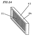
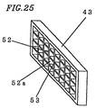
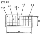
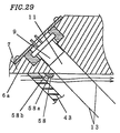
- FIG 24 is a perspective view illustrating an alternative embodiment of the propagation path flow regulator.
- Reference numeral 51 is a regulation section of the propagation path flow regulator 43 .
- the regulation section 51 is formed by a meshed member such as a wire mesh or a fabric having a small thickness in the flow direction.
- a similar member as the regulation section 51 can also be provided in the propagation path flow regulator 45 (not shown). It is understood that the propagation path flow regulator can be formed by a meshed member alone without using an outer frame 44a of the propagation path flow regulator.
- the regulation section 51 is formed by the meshed member having a small thickness in the flow direction, it is possible to reduce the size of the propagation path flow regulator 43 or 45 along the flow direction so that it can be installed in a small space, thereby reducing the size of the measurement flow path.
- Use of a material which does not easily reflect ultrasonic waves for the meshed member covering the ultrasonic wave propagation path 13 in combination with the use of the meshed member which has a large aperture ratio, provides an advantage of reducing the reflection of the ultrasonic waves by the propagation path flow regulator 43 or 45 , thereby reducing the influence of interference by reflected waves on the measurement precision and thus realizing a high-precision measurement.
- Figure 25 is a perspective view illustrating an alternative embodiment of the propagation path flow regulator.
- Reference numeral 52 is a regulation section of the propagation path flow regulator 43 .
- the regulation section 52 includes a lattice member 53 having many wall surfaces 52a extending along the flow direction.
- a similar member as the regulation section 52 can also be provided in the propagation path flow regulator 45 (not shown).
- each wall surface 52a can be directed to a direction such that the flow velocity distribution in the ultrasonic wave propagation path 13 is more equalized so that it is possible to further equalize the flow velocity distribution in the ultrasonic wave propagation path 13 , thereby improving the measurement precision.
- Figure 26 is a front view of an alternative embodiment of the propagation path flow regulator as viewed along the flow direction.
- Reference numeral 54 denotes regulation sections provided in the propagation path flow regulator 43 in which the interval between two adjacent regulation sections is varied depending on the position along the transverse section of the measurement flow path 6 so as to vary the cross-sectional area of each passage hole 55 .
- the cross-sectional area of a passage hole 55a along the periphery of the cross section of the propagation path flow regulator 43 is set to be greater than that of a passage hole 55b in the center portion of the propagation path flow regulator 43 .
- the cross-sectional area of the passage hole 55 increases toward the respective ends of the propagation path flow regulator 43 along the width W direction or the height H direction.
- a similar member as the regulation section 54 can also be provided in the propagation path flow regulator 45 (not shown).
- the propagation path flow regulator 43 When the propagation path flow regulator 43 is absent, it is difficult to obtain a uniform flow velocity distribution because the fluid flowing along the wall surface of the measurement flow path 6 has a reduced flow velocity due to the viscosity of the fluid, while the fluid flowing through the central portion of the measurement flow path 6 has a relatively large flow velocity.
- the propagation path flow regulator 43 is provided while the cross-sectional area of the passage hole 55 is reduced in the center portion of the cross section of the measurement flow path 6 so as to reduce the flow velocity.
- the cross-sectional area of the passage hole 55 is increased along the periphery so that the passage resistance is smaller than that in the center portion, thereby suppressing the decrease in the flow velocity.
- the flow velocity distribution in the ultrasonic wave propagation path 13 is equalized. Therefore, the flow velocity in the ultrasonic wave propagation path 13 which extends diagonally across the measurement flow path 6 is equalized from the upstream side to the downstream side, so that the measured value of the average flow velocity in the ultrasonic wave propagation path 13 can well conform with that measured across the cross section of the measurement flow path 6 over a wide flow rate range from the laminar flow range to the disturbed flow range, thereby stabilizing the change in the flow rate coefficient and increasing the measurement precision.
- the propagation path flow regulator 43 is provided immediately upstream of the ultrasonic wave propagation path 13 to extend along the entire area of the ultrasonic wave propagation path 13 from the upstream end to the downstream end thereof, thereby facilitating the disturbance of the flow across the entire area of the ultrasonic wave propagation path 13 .
- the characteristics of the correction coefficient due to flow rate change can be stabilized over the entire flow rate measurement range, thereby improving the measurement precision. Even when the physical property values of the fluid change, the measurement precision is maintained, thereby increasing the practicability and the convenience.
- the diagonal arrangement of the propagation path flow regulator 43 across the measurement flow path 6 it is possible to increase the aperture ratio thereof, thereby realizing a measurement device with a reduced pressure loss. Furthermore, by the diagonal arrangement of the propagation path flow regulator 43 across the measurement flow path 6 , it is possible to ensure a large area across which the regulation sections 44 can be provided. Thus, it is possible without increasing the pressure loss to reduce the interval between adjacent regulation sections 44 and to increase the number of the regulation sections 44 , thereby increasing the flow disturbance facilitating effect.
- the ultrasonic wave propagation path 13 is surrounded by the upstream and downstream propagation path flow regulators 43 and 45 , whereby it is possible to equalize the disturbance condition from the upstream side and the downstream side of the ultrasonic wave propagation path 13 , thereby further stabilizing the correction coefficient and further improving the measurement precision.
- the influence of the flow condition on the downstream side along the measurement flow path 6 is reduced by the downstream propagation path flow regulator 45 .
- the same effect is obtained both for a forward flow and a reverse flow along the measurement flow path, so that it is possible to stabilize the correction coefficient even for a pulsating flow or a reverse flow, thereby increasing the measurement precision.
- the upstream and the downstream propagation path flow regulators 43 and 45 are integrated together. Thus, it is possible to prevent and stabilize a shift in the distance between the propagation path flow regulators or a positional shift between the upstream regulation section and the downstream regulation section, thereby realizing a measurement device with reduced variation. Moreover, the connecting section reinforces the propagation path flow regulators, whereby it is possible to reduce the size or the thickness of the regulation section. Therefore, it is possible to equalize the flow condition in the ultrasonic wave propagation path or to reduce the loss of pressure in the measurement flow path.
- the measurement flow path irrespective of the type of the fluid to be measured by changing only the distance of the propagation path flow regulator from the ultrasonic wave propagation path 13 , thereby improving the convenience. Moreover, it is possible to maintain a stable measurement precision irrespective of the fluid to be measured. Furthermore, since the measurement flow path can be commonly used, it is possible to reduce the cost.
- the regulation section may be provided in the form of a meshed member.
- the regulation section may be provided in the form of a lattice member whose wall surfaces extend along the flow direction to regulate the flow direction, thereby further equalizing the flow velocity distribution in the ultrasonic wave propagation path and thus improving the measurement precision.
- the interval between two adjacent regulation sections may be varied depending on the position along the transverse section of the measurement flow path.
- elbow sections 17 and 18 are bent in the width W direction of the measurement flow path 6 has been illustrated in the present embodiment. However, it is understood that the elbow sections 17 and 18 may alternatively be bent in the height H direction of the measurement flow path 6 or any other direction, and the elbow sections 17 and 18 may be bent at different angles.
- Figure 27 is a cross-sectional view illustrating the structure of an ultrasonic flow meter according to Embodiment 5 of the present invention.
- like elements and functions to those of the embodiments shown in Figures 1 to 26 are provided with like reference numerals and will not be described in detail, and the parts which are different from the above embodiments will be focused on in the following description.
- Reference numeral 56 is an influent suppressor for reducing the inflow of the fluid to be measured into the aperture holes 11 and 12 .
- the influent suppressor 56 is provided on the downstream side of the above-described propagation path flow regulator 43 which is provided on the upstream side of the ultrasonic wave propagation path 13 .
- the influent suppressor 56 includes a first influent suppressor 57 formed by the aperture hole sealing section 21 having many ultrasonically transmissive holes 22 capable of transmitting an ultrasonic wave therethrough, as illustrated in an enlarged view of Figure 28 .
- the aperture hole sealing section 21 extends across the ultrasonic wave propagation path 13 and is coplanar with the measurement flow path surface 6a of the aperture holes 11 and 12 so as to reduce the amount of fluid flow into the aperture holes 11 and 12 .
- FIG 29 illustrates another embodiment of the influent suppressor.
- a first influent suppressor 58 includes a flow deflector 58a and a guide surface 58b .
- the flow deflector 58a is provided to protrude from the flow path wall 7 on the immediate upstream side of the upstream aperture hole 11 .
- the guide surface 58b is provided on the upstream side of the flow deflector 58a with a smoothly increasing height.
- the first influent suppressor 58 deflects the fluid flowing near the measurement flow path surface 6a away from the wall surface so that the fluid does not enter the aperture hole 11 .
- the flow deflector 58a and the guide surface 58b can be formed integrally with the propagation path flow regulator 43 so as to provide a second influent suppressor.
- reference numeral 60 is a second influent suppressor obtained by providing an influent suppressing section 60b with flow deflectors 60a on the side of a propagation path flow regulator 59 near the measurement flow path surface 6a .
- the propagation path flow regulator 59 and the second influent suppressor 60 are integrated together.
- the fluid to be measured enters the measurement flow path 6 with a non-uniform flow or a flow pulsation due to the increase/decrease in the flow path cross-sectional area provided by a control valve (not shown) which is provided on the upstream side of the measurement flow path 6 and/or due to the passage through the elbow section 17 .
- a control valve not shown
- the disturbance of the flow is facilitated by the regulation sections 44 of the propagation path flow regulator 43 provided immediately upstream of the ultrasonic wave propagation path 13 .
- the propagation path flow regulator 43 is provided immediately upstream of the ultrasonic wave propagation path 13 to extend all the way from the vicinity of the upstream ultrasonic transducer 8 to the vicinity of the downstream ultrasonic transducer 9 , whereby the flow disturbance is equally facilitated across the entire area of the ultrasonic wave propagation path 13 . In this way, the variation in the flow condition is reduced in the ultrasonic wave propagation path 13 from the upstream side to the downstream side so as to facilitate the measurement of the average flow velocity in the ultrasonic wave propagation path 13 .
- the flow disturbance is facilitated by the propagation path flow regulator 43 in the ultrasonic wave propagation path 13 .
- the difference between this flow disturbance and the flow disturbance which results in the ultrasonic wave propagation path 13 when the flow velocity is large (when the flow rate is large), and thus the fluid flows into the measurement flow path 6 as a disturbed flow is small. Therefore, it is possible to stably disturb the flow in the ultrasonic wave propagation path 13 over a wide flow rate range from a small flow rate to a large flow rate.
- the propagation path flow regulator 43 is arranged to extend diagonally across the measurement flow path 6 , whereby the propagation path flow regulator 43 can have a greater length within the measurement flow path 6 than that obtained when the propagation path flow regulator 43 is arranged to extend orthogonal to the measurement flow path 6. Therefore, it is possible to provide the propagation path flow regulator 43 with a large aperture ratio and to realize a measurement device with a reduced pressure loss.
- the flow in the vicinity of the aperture hole will be described.
- the first influent suppressor 57 or 58 provided for the downstream aperture hole 12 is used as the influent suppressor, it is possible to efficiently reduce the fluid flow into the downstream aperture hole around which a strong vortex easily occurs because the downstream aperture hole extends in a direction at an acute angle with respect to the flow so as to efficiently reduce flow disturbances between the ultrasonic transducers, thereby increasing the upper limit value for the flow rate measurement.
- the aperture hole sealing section 21 is the first influent suppressor 57 , it is possible to further increase the influent suppressing effect and to reduce the flow in the aperture hole.
- the amount of ultrasonic attenuation can be reduced, whereby it is possible to reduce the driving input for the ultrasonic transducers and to reduce the power consumption.
- the influent suppressor is the first influent suppressor 57 or 58 provided for both of the upstream and downstream aperture holes 11 and 12 .
- disturbances in the aperture hole which account for a major part of the total flow disturbance in the ultrasonic wave propagation path, can be reduced efficiently, whereby it is possible to increase the measurement precision and the upper limit value for the flow rate measurement.
- the aperture hole sealing section 21 is the first influent suppressor 57 , it is possible to efficiently reduce flow disturbances for either a forward flow or a reverse flow in the measurement flow path.
- the first influent suppressor 58 including the flow deflector 58a is provided for the upstream aperture hole 11 and the first influent suppressor 57 including the aperture hole sealing section 21 is provided for the downstream aperture hole 12 , it is possible to further reduce flow disturbances between the ultrasonic transducers and to reduce the amount of ultrasonic attenuation, thereby reducing the power consumption for the ultrasonic transducers.
- the influent suppressor is the second influent suppressor obtained by providing the propagation path flow regulator with the influent suppressing section, it is possible to suppress the flow into. the aperture hole. Furthermore, by the integration of the propagation path flow regulator with the influent suppressor, it is possible to reduce the variation in the suppression of the fluid flow into the aperture hole, thereby increasing the reliability. Moreover, it is possible to provide a compact ultrasonic wave propagation path, thereby reducing the size of the measurement flow path.
- the ultrasonic wave is transmitted and received between the ultrasonic transducers 8 and 9 along the ultrasonic wave propagation path 13 where the flow is stabilized.
- it is possible to realize high-precision flow velocity measurement, and to reduce the attenuation of the ultrasonic wave due to the variation in the flow, thereby increasing the upper limit value for the flow rate measurement.
- a strong flow in the measurement flow path 6 may flow into the aperture hole 12 thereby generating a strong vortex because the downstream aperture hole 12 extends in a direction at an acute angle with respect to the measurement flow path 6 , whereby the flow velocity measurement precision may be reduced due to a flow velocity fluctuation in a portion of the flow, and/or the upper limit value for the measurement may be reduced by an ultrasonic attenuation due to a vortex.
- the upstream aperture hole 11 in the absence of the first influent suppressor 57 or 58 or the second influent suppressor 60 , there occurs an influent of the flow.
- the influence is small because the aperture hole 11 extends in a direction at an obtuse angle with respect to the measurement flow path 6 whereby the strength of the vortex is smaller than the strength of the vortex occurring around the downstream aperture hole 12 . It is understood that it is possible to further stabilize the flow by providing the first influent suppressor 57 or 58 or the second influent suppressor 60 for the upstream aperture hole 11 .
- the propagation path flow regulator 43 is provided immediately upstream of the ultrasonic wave propagation path 13 to extend along the entire area of the ultrasonic wave propagation path 13 from the upstream end to the downstream end thereof, thereby facilitating the disturbance of the flow across the entire area of the ultrasonic wave propagation path 13 .
- the correction coefficient K is stabilized and has a reduced change for a change in the flow rate as in the case described above with reference to Figures 17 and 18 . Because the characteristics of the correction coefficient due to flow rate change is stabilized, the measurement precision is maintained even when the physical property values of the fluid change, thereby increasing the practicability and the convenience.
- the aperture hole sealing section is a meshed member of an inclined mesh pattern having an inclination with respect to a horizontal direction, or when the flow deflector is provided both on the upstream side and the downstream side of the aperture hole, it is possible stabilize the correction coefficient and to improve the measurement precision. Moreover, the effects described above in Embodiment 1 are additionally provided, thereby further improving the reliability.
- Figure 31 illustrates an alternative embodiment of the influent suppressor, which includes first influent suppressor 57 including the aperture hole sealing section 21 having the ultrasonically transmissive holes 22 , and a second influent suppressor 62 including an influent suppressing section 62a provided on the side of a propagation path flow regulator 61 near the measurement flow path surface 6a .
- first influent suppressor 57 including the aperture hole sealing section 21 having the ultrasonically transmissive holes 22
- second influent suppressor 62 including an influent suppressing section 62a provided on the side of a propagation path flow regulator 61 near the measurement flow path surface 6a .
- the aperture hole sealing section can be selected primarily in view of the ultrasonic transmissivity without so much concern about the clogging of the aperture hole sealing section, thereby increasing the freedom of the selection. Moreover, it is possible to further increase the ultrasonic transmissivity so as to reduce the power consumption, or to further increase the sensitivity so as to realize a device with a desirable measurement precision. Moreover, the second influent suppressor 62 can be processed into a shape suitable for the flow rate or the physical property values of the fluid to be measured as a part of the propagation path flow regulator 61 , whereby it is easy to commonly use the measurement flow path 6 itself.
- the disturbance in the aperture hole is reduced by the multiplier effect of the first and second influent suppressors, and variations in the suppression of the fluid flow into the aperture hole is reduced by the integration of the propagation path flow regulator and the influent suppressor. Therefore, it is possible to increase the measurement precision and the reliability. Moreover, it is possible to provide a compact ultrasonic wave propagation path, thereby reducing the size of the measurement flow path.
- FIGs 32 and 33 illustrate an alternative embodiment of the propagation path flow regulator and the influent suppressor.
- the ultrasonic wave propagation path 13 is surrounded by the upstream propagation path flow regulator 43 and the downstream propagation path flow regulator 45 , and the influent suppressor 56 is further provided.
- the propagation path flow regulators 43 and 4 5 are connected and integrated together by the connecting section 48 .
- the influent suppressor 56 is attached to the ultrasonic transmission window 49 .
- the influent suppressor 56 is a mesh as the aperture hole sealing section 21 which covers the aperture holes 11 and 12 .
- the flow in the ultrasonic wave propagation path 13 is equalized and stabilized due to the application of a back pressure by the downstream propagation path flow regulator 45 . Moreover, it is possible to perform a stable flow rate measurement by reducing the influence on the flow condition in the ultrasonic wave propagation path 13 from a pulsation, or the like, which occurs due to the variation in the downstream piping configuration or the conditions under which the fluid to be measured is used.
- the influent suppressor 56 is provided for the aperture holes 11 and 12 , so that it is possible to increase the upper limit value for the flow rate measurement.
- the propagation path flow regulators 43 and 45 are connected together, which is further integrated with the aperture hole sealing section 21 as the influent suppressor 56 . Therefore, the positional relationship, e.g., the distance between these elements, is defined, whereby it is possible to reduce the variations in the flow condition in the ultrasonic wave propagation path 13 and to realize a stable measurement with little variation. Moreover, because not only the propagation path flow regulators 43 and 45 are integrated together but also the aperture hole sealing section 21 is further integrated with the propagation path flow regulators 43 and 45 , it is possible to further increase the mechanical strength of the propagation path flow regulator. Thus, it is possible to prevent deformation over a long term use, thereby improving the durability and the reliability.
- the propagation path flow regulator 43 is arranged substantially parallel to the ultrasonic wave propagation path 13 along the width W direction of the measurement flow path 6
- the propagation path flow regulator 43 may be arranged within the measurement flow path 6 having a circular transverse cross section along the height H direction as described above with reference to Figure 16 . Effects similar to those of the previous embodiments can be expected by arranging the propagation path flow regulator 43 in the measurement flow path 6 having a rectangular transverse cross section, as described above with reference to Figure 22 .
- the aperture hole is shaped to have an aperture shape which has a side along a direction substantially perpendicular to the direction of the flow through the measurement flow path, or where the non-uniform flow suppressor is provided in the introduction section on the upstream side of the measurement flow path or in the exit section on the downstream side of the measurement flow path.
- the propagation path flow regulator 43 is provided immediately upstream of the ultrasonic wave propagation path 13 to extend along the entire area of the ultrasonic wave propagation path 13 from the upstream end to the downstream end thereof, thereby facilitating the disturbance of the flow across the entire area of the ultrasonic wave propagation path 13 .
- the characteristics of the correction coefficient due to flow rate change can be stabilized over the entire flow rate measurement range, thereby preventing an increase in the error due to the correction coefficient and improving the measurement precision.
- the influent suppressor can be provided to reduce the fluid flow into the aperture hole, thereby significantly reducing flow disturbances in the ultrasonic wave propagation path. Therefore, it is possible to increase the ultrasonic reception level and to increase the upper limit value for the flow rate measurement.
- the influent suppressor may be a first influent suppressor provided for the downstream aperture hole.
- the influent suppressor is arranged for the downstream aperture hole around which a strong vortex easily occurs because the downstream aperture hole extends in a direction at an acute angle with respect to the flow. Therefore, it is possible to reduce the fluid flow into the aperture hole so as to efficiently reduce flow disturbances between the ultrasonic transducers, thereby increasing the upper limit value for the flow rate measurement.
- the influent suppressor may be the first influent suppressor provided for the upstream aperture hole and the downstream aperture hole.
- the influent suppressor may be the second influent suppressor which is obtained by providing the propagation path flow regulator with an influent suppressing section.
- the first influent suppressor may be the aperture hole sealing section having at least one ultrasonically transmissive hole.
- the aperture hole sealing section can be provided only for the downstream aperture hole, in which case it is possible to further reduce the attenuation of the ultrasonic wave, thereby reducing the driving input for the ultrasonic transducers and the power consumption.
- the first influent suppressor may include the aperture hole sealing section having the ultrasonically transmissive hole and the flow deflector provided in a vicinity of the aperture hole.
- the aperture hole sealing section can be selected primarily in view of the ultrasonic transmissivity without so much concern about the clogging of the aperture hole sealing section, thereby increasing the freedom of the selection.
- it is possible to further increase the ultrasonic transmissivity so as to reduce the power consumption, or to further increase the sensitivity so as to realize a device with a desirable measurement precision.
- the influent suppressor may include the first influent suppressor provided for the aperture hole and the second influent suppressor obtained by providing the propagation path flow regulator with an influent suppressing section.
- the disturbance in the aperture hole is reduced by the multiplier effect of the first and second influent suppressors, and variations in the suppression of the fluid flow into the aperture hole is reduced by the integration of the propagation path flow regulator and the influent suppressor. Therefore, it is possible to increase the measurement precision and the reliability. Moreover, it is possible to provide a compact ultrasonic wave propagation path, thereby reducing the size of the measurement flow path.
- elbow sections 17 and 18 are bent in the width W direction of the measurement flow path 6 has been illustrated in the present embodiment. However, it is understood that the elbow sections 17 and 18 may alternatively be bent in the height H direction of the measurement flow path 6 or any other direction, and the elbow sections 17 and 18 may be bent at different angles.
- Figure 34 is a cross-sectional view illustrating a flow path of an ultrasonic flow meter according to Embodiment 6 of the present invention.
- like elements and functions to those of the embodiments shown in Figures 1 to 33 are provided with like reference numerals and will not be described in detail, and the parts which are different from the above embodiments will be focused on in the following description.
- Reference numeral 63 denotes partitioned paths provided in each of the aperture holes 11 and 12 .
- the partitioned paths 63 are obtained by partitioning each of the aperture holes 11 and 12 along the ultrasonic propagation direction. As illustrated in Figure 35 , the partitioned paths 63 have an inlet surface 65 extending along a vibration surface 64 of the ultrasonic transducer 9 and an outlet surface 66 extending along the measurement flow path surface 6a .
- One side 67 of the vertical section of the partitioned paths 63 has a dimension which is longer than the half wavelength ⁇ /2 of the ultrasonic wave used for transmission/reception and is not an integral multiple of the half wavelength of the ultrasonic wave.
- a distance 68 between the partitioned paths 63 in the aperture hole 12 and the vibration surface of the ultrasonic transducer 9 is an integral multiple of the half wavelength ⁇ /2 of the ultrasonic wave.
- the thickness of each partition of the partitioned paths 63 has a dimension which is shorter than the wavelength ⁇ of the ultrasonic wave.
- each of the partitioned paths 63 of the aperture hole 11 provided along the measurement flow path surface 6a which opposes the ultrasonic transducer 9 is arranged to extend colinearly with a corresponding one of the partitioned paths 63 of the other aperture hole 12 .
- the ultrasonic flow meter obtains the flow velocity V as shown in the following expression based on the difference between the inverse of the ultrasonic propagation time T1 and the inverse of the ultrasonic propagation time T2, and converts the flow velocity V into the flow rate by multiplying the flow velocity V by the cross-sectional area of the flow path.
- the ultrasonic propagation distance L which is influenced by the flow, varies depending on whether the flow enters the aperture hole. Specifically, a flow may or may not enter the aperture hole depending upon the flow velocity or the presence/absence of a pulsating flow, thereby varying the effective propagation distance L and causing an error in the measured flow rate.
- each aperture hole provided in the measurement flow path is divided into smaller sections.
- a vortex is less likely to occur and it is possible to reduce the flow of the fluid into the aperture hole by the function of the partitioned paths as an influent suppressor. Therefore, it is possible to maintain the effective propagation distance L constant and to properly measure the flow rate even when the flow velocity changes or a pulsation occurs.
- the ultrasonic wave propagates through the fluid to be measured within the partitioned paths, the decrease in the sensitivity is less than that which would result when using a bulk element.
- due to the partitioning of the paths it is possible to maintain the rectilinear property of the ultrasonic waves and to realize a desirable transmission/reception thereof.
- the ultrasonic waves can enter the partitioned paths at a right angle and thus travel therethrough in a straight path, an ultrasonic wave propagation path with no reflection and little attenuation is provided. Furthermore, since the outlet is a flat surface with respect to the measurement flow path surface, there is no disturbance in the flow in the periphery layer along the measurement flow path surface. Moreover, due to the alignment of the outlet surface as the radiation surface, it is possible to radiate the ultrasonic wave efficiently.
- the transmission surface of one of the pair of partitioned paths is aligned with the reception surface of the other one of the partitioned paths along the traveling direction of the ultrasonic wave, whereby it is possible to eliminate the reflective attenuation thereof due to the partition plate in the partitioned paths of the opposing aperture hole.
- the side 67 of the vertical section of each of the partitioned paths is longer than the half wavelength.
- the viscosity influence from the partition surface is reduced, whereby it is possible to provide partitioned paths with little attenuation.
- the distance 68 between the ultrasonic transducer and the inlet surface of the partitioned paths can be set such that a resonance is provided at the half wavelength, whereby it is possible to provide an efficient radiation.
- the thickness d of each partition of the partitioned paths can be set to be shorter than the wavelength so as to prevent the reflection of the ultrasonic wave as it enters the partitioned paths, thereby providing an efficient propagation of the ultrasonic wave and realizing a desirable transmission/reception.
- One of the partitioned paths has its opening at the center of the aperture hole.
- the aperture hole is aligned with the central axis of the ultrasonic transducer, thereby efficiently effecting the propagation in the center area where the output of the ultrasonic wave is high, thereby improving the signal transmission by the ultrasonic transmission/reception.
- the propagation along a direction perpendicular to the travelling direction of the ultrasonic wave is diffused so that a resonance is unlikely to occur, thereby providing an effect that the ultrasonic wave propagates efficiently.
- a honeycomb lattice material is used for the partitioned paths with an opening at the center of the partitioned paths, it is possible to make more efficient the signal transmission by the ultrasonic transmission/reception due to the above-described reduction in the resonance phenomenon, the effect provided by the sufficiently small thickness d of the partition, and the efficient propagation of the ultrasonic wave in the center area where the output of the ultrasonic wave is high.
- each of the partitioned paths may include a communication section 69 at a certain point along its length for communicating the partitioned path with an adjacent one of the partitioned paths.
- the size of the communication section 69 may also be greater than the wavelength of the ultrasonic wave so that the partitioned paths can easily be connected to each other.
- Figure 42 is a cross-sectional view illustrating partitioned paths 70 of the aperture hole 12 .
- the partitioned paths are obtained by providing a wire mesh as a mesh material on the ultrasonic transducer side along a direction perpendicular to the ultrasonic propagation direction and on the flow path side along the flow path wall surface, whereby the path length Lb of th partitioned paths is shorter than the wavelength ⁇ of the ultrasonic wave used for transmission/reception.
- Figure 43 illustrates an opening 71 .
- each partitioned path can serve as a propagation path with little attenuation.
- the aperture space in each aperture hole provided along the measurement flow path surface is divided into smaller portions so that a vortex is unlikely occur and it is possible to reduce the flow of the fluid into the aperture hole. Therefore, even when the flow velocity changes or a pulsation occurs, the flow rate can be properly measured.
- the ultrasonic wave propagates through the air in the partitioned paths, the decrease in the sensitivity is less than that which would result when using a bulk element.
- the division of the path it is possible to maintain the rectilinear property of the ultrasonic waves and to realize a desirable transmission/reception thereof.
- the side 67 of the vertical cross section of the partitioned paths is longer than the half wavelength, it is possible to provide a propagation path which is less susceptible to the viscosity of the fluid flowing along the partition surface and thus has little attenuation. Moreover, by setting the length of the side 67 not to be an integral multiple of the wavelength so as to suppress resonance in the lateral direction, thereby realizing an efficient propagation.
- the ultrasonic flow meter of the present invention provides the following effects.
- the ultrasonic flow meter of the present invention includes: a first influent suppressor provided in a vicinity of at least the downstream aperture hole for reducing inflow of the fluid to be measured into the aperture hole; and a second influent suppressor provided on an upstream side of the measurement flow path with respect to the aperture holes for reducing the inflow of the fluid to be measured into the aperture holes, wherein the first influent suppressor provided for the downstream aperture hole includes an aperture hole sealing section having at least one ultrasonically transmissive hole.
- the ultrasonic flow meter of the present invention includes a first influent suppressor and a second influent suppressor for reducing inflow of the fluid to be measured into the aperture holes for both a forward flow and a reverse flow of the fluid to be measured, wherein: the first influent suppressor provided for the aperture hole which is on the downstream side when the fluid flows in a forward direction is an aperture hole sealing section having at least one ultrasonically transmissive hole; and the second influent suppressor is provided on both an inlet side and an outlet side of the measurement flow path.
- the ultrasonic flow meter of the present invention includes a propagation path flow regulator provided along an ultrasonic wave propagation path between the upstream ultrasonic transducer and the downstream ultrasonic transducer and having a regulation section exposed to the flow.
- the regulation section of the propagation path flow regulator arranged immediately upstream of the ultrasonic wave propagation path facilitates the disturbance of the flow across the entire zone from the upstream side to the downstream side of the ultrasonic wave propagation path.
- the flow condition is equally disturbed across the entire area of the ultrasonic wave propagation path along the width direction from an area near the upstream aperture hole to an area near the downstream aperture hole irrespective of the flow rate, whereby it is possible to reduce the changes in the correction coefficient across the entire flow rate measurement zone, thereby preventing increases in the error due to the correction coefficient and increasing the measurement precision.
- the measurement precision is maintained even when the Reynolds number changes due to the change in the kinematic viscosity of the fluid, whereby it is possible to realize a measurement device which is resistant against changes in the temperature of the fluid or changes in the composition of the fluid, thereby increasing the practicability of the device.
- the ultrasonic flow meter of the present invention includes: a propagation path flow regulator provided along an ultrasonic wave propagation path between the upstream ultrasonic transducer and the downstream ultrasonic transducer and having a regulation section exposed to the flow; and an influent suppressor for reducing inflow of the fluid to be measured into the aperture hole.
- the regulation section of the propagation path flow regulator arranged immediately upstream of the ultrasonic wave propagation path facilitates the disturbance of the flow across the entire zone from the upstream side to the downstream side of the ultrasonic wave propagation path.
- the flow condition is equally disturbed across the entire area of the ultrasonic wave propagation path along the width direction from an area near the upstream aperture hole to an area near the downstream aperture hole irrespective of the flow rate, whereby it is possible to reduce the changes in the correction coefficient across the entire flow rate measurement zone, thereby preventing increases in the error due to the correction coefficient and increasing the measurement precision.
- the influent suppressor for the aperture hole which opens into the measurement flow path so as to reduce the fluid flow into the aperture hole, thereby significantly reducing flow disturbances along the ultrasonic wave propagation path between the ultrasonic transducers and increasing the upper limit value for the flow rate measurement.
- the first influent suppressor provided for the upstream aperture hole is a flow deflector.
- the first influent suppressor provided for the upstream aperture hole is an aperture hole sealing section having at least one ultrasonically transmissive hole.
- an aperture ratio of the aperture hole sealing section provided for the upstream aperture hole is greater than an aperture ratio of the aperture hole sealing section provided for the downstream aperture hole.
- the propagation path flow regulator is arranged on the upstream side and the downstream side with respect to the ultrasonic wave propagation path.
- the ultrasonic wave propagation path is surrounded by the upstream and downstream propagation path flow regulators, whereby it is possible to equalize the disturbance condition from the upstream side and the downstream side of the ultrasonic wave propagation path, thereby further stabilizing the correction coefficient and further improving the measurement precision.
- the influence of the flow condition on the downstream side along the measurement flow path is reduced by the downstream propagation path flow regulator.
- the same effect is obtained both for a forward flow and a reverse flow along the measurement flow path, so that it is possible to stabilize the correction coefficient even for a pulsating flow, thereby increasing the measurement precision.
- the propagation path flow regulators arranged on the upstream side and the downstream side with respect to the ultrasonic wave propagation path are integrated together via a connector section.
- the connecting section reinforces the propagation path flow regulators, whereby it is possible to reduce the size or the thickness of the regulation section. Therefore, it is possible to equalize the flow condition in the ultrasonic wave propagation path or to reduce the loss of pressure in the measurement flow path.
- the propagation path flow regulators arranged on the upstream side and the downstream side with respect to the ultrasonic wave propagation path and the influent suppressor are integrated together.
- the positional relationship e.g., distance
- the upstream and downstream propagation path flow regulators and the influent suppressor thereby stabilizing the flow condition. Therefore, it is possible to reduce the variations in the flow condition in the ultrasonic wave propagation path and to realize a stable measurement with little variation. It is possible by such integration to further increase the mechanical strength of the propagation path flow regulator, thereby preventing its deformation over a long term use and thus improving its durability and reliability.
- the influent suppressor is a first influent suppressor provided for the downstream aperture hole.
- the influent suppressor is arranged for the downstream aperture hole around which a strong vortex easily occurs because the downstream aperture hole extends in a direction at an acute angle with respect to the flow. Therefore, it is possible to reduce the fluid flow into the aperture hole so as to efficiently reduce flow disturbances between the ultrasonic transducers, thereby increasing the upper limit value for the flow rate measurement.
- the influent suppressor is a first influent suppressor provided for the upstream aperture hole and the downstream aperture hole.
- the influent suppressor is a second influent suppressor which is obtained by providing the propagation path flow regulator arranged along the ultrasonic wave propagation path with an influent suppressing section.
- the influent suppressor includes a first influent suppressor provided for the aperture hole and a second influent suppressor obtained by providing the propagation path flow regulator with an influent suppressing section.
- the disturbance in the aperture hole is reduced by the multiplier effect of the first and second influent suppressors, and variations in the suppression of the fluid flow into the aperture hole is reduced by the integration of the propagation path flow regulator and the influent suppressor. Therefore, it is possible to increase the measurement precision and the reliability. Moreover, it is possible to provide a compact ultrasonic wave propagation path, thereby reducing the size of the measurement flow path.
- the first influent suppressor is an aperture hole sealing section having at least one ultrasonically transmissive hole.
- the aperture hole sealing section By covering the aperture hole with the aperture hole sealing section, it is possible to further increase the effect of suppressing the flow of the fluid to be measured into the aperture hole, thereby reducing and stabilizing the flow in the aperture hole.
- the first influent suppressor includes an aperture hole sealing section having at least one ultrasonically transmissive hole and a flow deflector provided in a vicinity of the aperture hole.
- an aperture hole sealing section having at least one ultrasonically transmissive hole and a flow deflector provided in a vicinity of the aperture hole.
- an aperture ratio of the aperture hole sealing section provided for the upstream aperture hole is greater than an aperture ratio of the aperture hole sealing section provided for the downstream aperture hole.
- the aperture hole sealing section is a meshed member of an inclined mesh pattern having an inclination with respect to a horizontal direction.
- the pattern is inclined with respect to the horizontal direction, so that it is possible to facilitate settling of minute particles such as dust attached onto the inclined mesh portions, thereby reducing the amount of such minute particles deposited and thus preventing clogging of the meshed member. Therefore, it is possible to ensure propagation of the ultrasonic wave therethrough and to maintain a stable measurement precision over a long time, thereby improving the durability and reliability.
- the flow deflector is provided on the upstream side and the downstream side of the aperture hole.
- a distance between the propagation path flow regulator and the ultrasonic propagation path is varied depending on a type of the fluid to be measured.
- the measurement flow path irrespective of the type of the fluid to be measured by changing only the propagation path flow regulator, thereby improving the convenience, and to maintain a stable measurement precision irrespective of the fluid to be measured.
- the measurement flow path can be commonly used, it is possible to reduce the cost.
- the regulation section of the propagation path flow regulator is provided in the form of a meshed member.
- the regulation section of the propagation path flow regulator is provided in the form of a lattice member whose wall surfaces extend along the flow direction.
- an interval between two adjacent regulation sections of the propagation path flow regulator is varied depending on a position along a transverse section of the measurement flow path.
- a cross section of the measurement flow path along a direction perpendicular to the flow therethrough has a rectangular shape.
- the rectangular cross section it is possible to increase the measurement area with respect to the total measurement cross-sectional area, thereby allowing for a flow measurement under the same condition from the upstream side to the downstream side of the ultrasonic wave propagation path.
- a cross section of the measurement flow path along a direction perpendicular to the flow therethrough has a rectangular shape with an aspect ratio less than 2.
- the aperture hole opens into the measurement flow path in a shape which has a side extending along a direction substantially perpendicular to the direction of the flow through the measurement flow path.
- an introduction section arranged on the upstream side of the measurement flow path is provided with a non-uniform flow suppressor which has a passage opening with a minute aperture.
- an introduction section arranged on the upstream side of the measurement flow path and an exit section arranged on the downstream side of the measurement flow path are each provided with a non-uniform flow suppressor which has a passage opening with a minute aperture.
- a cross-sectional area of the introduction section or the exit section is greater than a cross-sectional area of the measurement flow path.
- an aperture size of the passage opening of the non-uniform flow suppressor is less than an aperture size of a passage opening provided in the second influent suppressor.
- another ultrasonic flow meter of the present invention includes: a measurement flow path through which a fluid to be measured flows; ultrasonic transducers provided respectively on an upstream side and a downstream side with respect to each other along the measurement flow path; and an upstream aperture hole and a downstream aperture hole, the aperture holes for exposing the ultrasonic transducers to the measurement flow path, wherein at least one of the aperture holes includes a plurality of partitioned paths extending along a propagation direction of the ultrasonic wave.
- the aperture flow path within the aperture hole provided along the side surface of the flow path is divided into small parts, whereby a vortex is less likely to occur and it is possible to reduce the flow of the fluid into the aperture hole. Therefore, it is possible to properly measure the flow rate even when a pulsation occurs.
- At least one of the aperture holes includes a plurality of partitioned paths extending along a propagation direction of the ultrasonic wave.
- the fluid flow into the aperture hole can be reduced by the influent suppressor and the upper limit value for the measurement can be improved.
- the ultrasonic wave propagates through the fluid within the partitioned paths, there is little decrease in the sensitivity.
- the partitioning of the paths it is possible to maintain the rectilinear property of the ultrasonic waves and to realize a desirable transmission/reception thereof.
- the aperture flow path within the aperture hole provided along the side surface of the flow path is divided into small parts, whereby a vortex is less likely to occur and it is possible to further reduce the flow of the fluid into the aperture hole. Therefore, it is possible to properly measure the flow rate even when a pulsation occurs.
- each of the partitioned paths has an inlet surface extending along a vibration surface of the ultrasonic transducer and an outlet surface extending along a wall surface of the measurement flow path.
- the ultrasonic waves can enter the partitioned paths at a right angle and thus travel therethrough in a straight path, an ultrasonic wave propagation path with no reflection and little attenuation is provided.
- the outlet is a flat surface with respect to the wall surface of the flow path, there is no disturbance in the flow in the periphery layer along the wall surface of the flow path.
- due to the alignment of the outlet surface as the radiation surface it is possible to radiate the ultrasonic wave efficiently.
- each of the partitioned paths of one of the aperture holes extends colinearly with a corresponding one of the partitioned paths of the other aperture hole.
- the transmission surface and the reception surface are aligned with each other along the traveling direction of the ultrasonic wave, whereby it is possible to reduce the reflective attenuation thereof due to the partition plate in the partitioned paths of the opposing aperture hole.
- one side of a vertical section of each of the partitioned paths is longer than a half wavelength of an ultrasonic wave used for transmission/reception.
- the viscosity influence from the partition surface is reduced, whereby it is possible to provide partitioned paths with little attenuation.
- one side of a vertical section of each of the partitioned paths is not an integral multiple of a half wavelength of an ultrasonic wave used for transmission/reception.
- it is possible to suppress resonance in the lateral direction, thereby realizing an efficient propagation.
- a distance between the partitioned paths of the aperture hole and the vibration surface of a corresponding one of the ultrasonic transducers is an integral multiple of a half wavelength of the ultrasonic wave.
- resonance is provided at the half wavelength, whereby it is possible to provide an efficient radiation.
- a thickness of each partition of the partitioned paths is shorter than the wavelength of an ultrasonic wave used for transmission/reception.
- the partitioned paths are formed by fitting a honeycomb lattice into the aperture hole.
- a lattice it is possible to divide each aperture hole in the vertical and lateral directions.
- one of the partitioned paths has its opening at a center of the aperture hole.
- the aperture hole is aligned with the center of the ultrasonic transducer, thereby allowing for an efficient transmission/reception.
- a path length of each of the partitioned paths is shorter than the wavelength of an ultrasonic wave used for transmission/reception.
- the partitioned paths are formed by arranging a net member in the aperture hole along a direction perpendicular to a propagation direction of the ultrasonic wave.
- each of the partitioned paths includes a communication section at a certain point along its length for communicating the partitioned path with an adjacent one of the partitioned paths.
Landscapes
- Physics & Mathematics (AREA)
- Fluid Mechanics (AREA)
- General Physics & Mathematics (AREA)
- Electromagnetism (AREA)
- Measuring Volume Flow (AREA)
Abstract
An ultrasonic flow meter of the present invention
includes: a measurement flow path 6 through which a fluid
to be measured flows; ultrasonic transducers 8 and 9
provided respectively on an upstream side and a downstream
side with respect to each other along the measurement flow
path 6; an upstream aperture hole 11 and a downstream
aperture hole 12, the aperture holes 11 and 12 for exposing
the ultrasonic transducers 8 and 9 to the measurement flow
path 6; a first influent suppressor 15 provided in a
vicinity of at least the downstream aperture hole 12 for
reducing inflow of the fluid to be measured into the aperture
hole 12; a second influent suppressor 16 provided on an
upstream side of the measurement flow path 6 with respect
to the aperture holes 11 and 12 for reducing the inflow of
the fluid to be measured into the aperture holes 11 and 12;
a measurement control section 19 for measuring a propagation
time of an ultrasonic wave between the ultrasonic
transducers 8 and 9; and a calculation section 20 for
calculating a flow rate based on a signal from the
measurement control section 19. The first influent suppressor
15 provided for the downstream aperture hole 12
comprises an aperture hole sealing section 21 having at
least one ultrasonically transmissive hole 22. Thus, it is
possible to stabilize the flow between the ultrasonic
transducers so as to enhance the ultrasonic reception level,
thereby increasing the measurement precision and the upper
limit value for the flow rate measurement, and to reduce
the driving input for the ultrasonic transducers.
Description
The present invention relates to an ultrasonic flow
meter for ultrasonically measuring a flow rate and/or a flow
velocity of a gas or a fluid.
Conventionally, ultrasonic flow meters of this type
are known in the art such as that disclosed in Japanese
Laid-Open Publication No. 11-351926. As illustrated in
Figure 44, an ultrasonic flow meter includes measurement
pipe 1 for allowing a fluid to flow from one end to the other
end thereof, an upstream ultrasonic transducer 2a, and a
downstream ultrasonic transducer 2b. The upstream ultrasonic
transducer 2a and the downstream ultrasonic transducer
2b oppose each other via the measurement pipe 1
therebetween with a predetermined angle with respect to the
center line of the measurement pipe 1. The upstream
ultrasonic transducer 2a and the downstream ultrasonic
transducer 2b are housed in depressions 3a and 3b,
respectively, of the measurement pipe 1. A flow variation
suppressing section 5 is further provided on an inlet side 4
of the measurement pipe 1. A fluid entering the measurement
pipe 1 is regulated by the flow variation suppressing
section 5 so as to reduce the inclination of the flow line
in the measurement section and/or to suppress the generation
of a vortex, thereby reducing the variation in the ultrasonic
reception level due to the reflection and/or refraction of
the ultrasonic wave at the interface of a flow disturbance,
and thus preventing the measurement precision from
deteriorating.
Other conventional examples are known in the art
such as that disclosed in Japanese Laid-Open Publication
No. 63-26537. As illustrated in Figure 45, a pair of the
ultrasonic transducers 2a and 2b are provided along the wall
surface of the measurement pipe 1 respectively on the
upstream side and the downstream side with respect to each
other. The ultrasonic transducers 2a and 2b are housed in
the depressions 3a and 3b, respectively, provided in the
measurement pipe 1, with a bulk ultrasonically transmissive
member 3c in the cavity space of each of the depressions 3a
and 3b, so as to prevent a flow from entering the
depressions 3a and 3b, thereby providing a high-precision
flow rate measurement.
With the conventional structure as illustrated in
Figure 44, it is possible to reduce flow disturbances in
the measurement section of the measurement pipe 1 and the
depressions 3a and 3b by the flow variation suppressing
section 5, thereby reducing the deterioration of the
measurement precision. However, when the flow rate through
the measurement pipe 1 increases, the fluid flows into the
depressions 3a and 3b to cause a vortex, thereby increasing
the flow disturbance between the ultrasonic transducers 2a
and 2b. In such a case, the ultrasonic wave is reflected
or refracted by the increased vortex, thereby lowering the
ultrasonic reception level. Thus, it is difficult to reduce
the driving input for the ultrasonic transducers 2a and 2b.
With the conventional structure as illustrated in
Figure 45 in which the bulk ultrasonically transmissive
member 3c is provided in each of the depressions 3a and 3b,
a propagation loss may occur during the propagation of the
ultrasonic wave through the bulk ultrasonically
transmissive member 3c, thereby lowering the ultrasonic
transmission output or the ultrasonic reception sensitivity.
Moreover, because the ultrasonic wave is propagated through
a solid as it passes through the bulk ultrasonically
transmissive member 3c, the rectilinear property thereof
is reduced so that it is difficult to radiate the ultrasonic
wave toward the opposing ultrasonic transducer. Thus, it
is difficult to reduce the power consumption of the flow
meter so that it can be used as a device such as a gas meter
for measuring the amount of a fuel gas for household use
such as town gas or LPG which is used over an extended period
of time, e.g., 10 years, with only a small electric cell
capacity.
The present invention solves the above-described
problems. An objective of the present invention is to reduce
the generation of flow disturbances or vortices between
ultrasonic transducers so as to enhance the ultrasonic
reception level, thereby increasing the measurement
precision and the upper limit value for the flow rate
measurement, and reducing the power consumption by reducing
the driving input for the ultrasonic transducers.
An ultrasonic flow meter of the present invention
includes: a measurement flow path through which a fluid to
be measured flows; ultrasonic transducers provided
respectively on an upstream side and a downstream side with
respect to each other along the measurement flow path; an
upstream aperture hole and a downstream aperture hole, the
aperture holes for exposing the ultrasonic transducers to
the measurement flow path; a first influent suppressor
provided in a vicinity of at least the downstream aperture
hole for reducing inflow of the fluid to be measured into
the aperture hole; a second influent suppressor provided
on an upstream side of the measurement flow path with respect
to the aperture holes for reducing the inflow of the fluid
to be measured into the aperture holes; a measurement control
section for measuring a propagation time of an ultrasonic
wave between the ultrasonic transducers; and a calculation
section for calculating a flow rate based on a signal from
the measurement control section, wherein the first influent
suppressor provided for the downstream aperture hole includes
an aperture hole sealing section having at least one
ultrasonically transmissive hole. Thus, it is possible to
stabilize the flow between the ultrasonic transducers so
as to enhance the ultrasonic reception level, thereby
increasing the measurement precision and the upper limit
value for the flow rate measurement, and to reduce the
driving input for the ultrasonic transducers by the
enhancement of the ultrasonic reception level and by
improving the attenuation of the ultrasonic wave by
providing the influent suppressor.
Another ultrasonic flow meter of the present
invention includes: a measurement flow path through which
a fluid to be measured flows; ultrasonic transducers
provided respectively on an upstream side and a downstream
side with respect to each other along the measurement flow
path; an upstream aperture hole and a downstream aperture
hole, the aperture holes for exposing the ultrasonic
transducers to the measurement flow path; a first influent
suppressor and a second influent suppressor for reducing
inflow of the fluid to be measured into the aperture holes
for both a forward flow and a reverse flow of the fluid to
be measured; a measurement control section for measuring
a propagation time of an ultrasonic wave between the
ultrasonic transducers; and a calculation section for
calculating a flow rate based on a signal from the
measurement control section, wherein: the first influent
suppressor provided for the aperture hole which is on the
downstream side when the fluid flows in a forward direction
is an aperture hole sealing section having at least one
ultrasonically transmissive hole; and the second influent
suppressor is provided on both an inlet side and an outlet
side of the measurement flow path. Thus, even when the flow
has a pulsation and causes a momentary reverse flow, it is
possible to reduce, as in the case of a forward flow, the
inflow of the fluid to be measured into the aperture hole,
and to significantly reduce flow disturbances between the
ultrasonic transducers, thereby increasing the measurement
precision and the upper limit value for the flow rate
measurement.
Another ultrasonic flow meter of the present
invention includes: a measurement flow path through which
a fluid to be measured flows; ultrasonic transducers
provided respectively on an upstream side and a downstream
side with respect to each other along the measurement flow
path; aperture holes for exposing each ultrasonic transducer
to the measurement flow path; a propagation path flow
regulator provided along an ultrasonic wave propagation path
between the upstream ultrasonic transducer and the downstream
ultrasonic transducer and having a regulation section
exposed to the flow; a measurement control section for
measuring a propagation time of an ultrasonic wave between
the ultrasonic transducers; and a calculation section for
calculating a flow rate based on a signal from the
measurement control section. Thus, the regulation section
of the propagation path flow regulator arranged immediately
upstream of the ultrasonic wave propagation path facilitates
the disturbance of the flow across the entire zone from the
upstream side to the downstream side of the ultrasonic wave
propagation path. Therefore, in the ultrasonic wave
propagation path, the flow condition is equally disturbed
across the entire area of the ultrasonic wave propagation
path along the width direction from an area near the upstream
aperture hole to an area near the downstream aperture hole
irrespective of the flow rate, whereby it is possible to
reduce the changes in the correction coefficient across the
entire flow rate measurement zone, thereby preventing
increases in the error due to the correction coefficient
and increasing the measurement precision. Thus, the
measurement precision is maintained even when the Reynolds
number changes due to the change in the kinematic viscosity
of the fluid, whereby it is possible to realize a measurement
device which is resistant against changes in the temperature
of the fluid or changes in the composition of the fluid,
thereby increasing the practicability of the device.
Another ultrasonic flow meter of the present
invention includes: a measurement flow path through which
a fluid to be measured flows; ultrasonic transducers
provided respectively on an upstream side and a downstream
side with respect to each other along the measurement flow
path; aperture holes for exposing each ultrasonic transducer
to the measurement flow path; a propagation path flow
regulator provided along an ultrasonic wave propagation path
between the upstream ultrasonic transducer and the downstream
ultrasonic transducer and having a regulation section
exposed to the flow; an influent suppressor for reducing
inflow of the fluid to be measured into the aperture hole;
a measurement control section for measuring a propagation
time of an ultrasonic wave between the ultrasonic
transducers; and a calculation section for calculating a
flow rate based on a signal from the measurement control
section. Thus, the regulation section of the propagation
path flow regulator arranged immediately upstream of the
ultrasonic wave propagation path facilitates the disturbance
of the flow across the entire zone from the upstream
side to the downstream side of the ultrasonic wave
propagation path. Therefore, in the ultrasonic wave
propagation path, the flow condition is equally disturbed
across the entire area of the ultrasonic wave propagation
path along the width direction from an area near the upstream
aperture hole to an area near the downstream aperture hole
irrespective of the flow rate, whereby it is possible to
reduce the changes in the correction coefficient across the
entire flow rate measurement zone, thereby preventing
increases in the error due to the correction coefficient
and increasing the measurement precision. Moreover, it is
possible to arrange the influent suppressor for the aperture
hole which opens into the measurement flow path so as to
reduce the fluid flow into the aperture hole, thereby
significantly reducing flow disturbances along the
ultrasonic wave propagation path between the ultrasonic
transducers and increasing the upper limit value for the
flow rate measurement.
In one embodiment, the first influent suppressor
provided for the upstream aperture hole is a flow deflector.
Thus, it is possible to eliminate the propagation losses
of the ultrasonic waves through the ultrasonically
transmissive hole for the upstream aperture hole, thereby
reducing the driving input for the ultrasonic transducers,
and to reduce the flow of the fluid into the upstream aperture
hole, thereby stabilizing flow disturbances along the
ultrasonic wave propagation path and improving the
measurement precision.
In one embodiment, the first influent suppressor
provided for the upstream aperture hole is an aperture hole
sealing section having at least one ultrasonically
transmissive hole. Thus, it is possible to significantly
reduce the inflow of the fluid into the upstream and
downstream aperture holes, thereby increasing the upper
limit value for the flow rate measurement and increasing
the measurement precision even for a flow which is
accompanied by a reverse flow. Moreover, it is possible to
realize an ultrasonic transmission/reception with desirable
S/N characteristics by the significant reduction in
flow disturbances due to the aperture hole. Thus, it is
possible to reduce the transmission output and the driving
input, thereby reducing the power consumption.
In one embodiment, an aperture ratio of the aperture
hole sealing section provided for the upstream aperture hole
is greater than an aperture ratio of the aperture hole
sealing section provided for the downstream aperture hole.
Thus, propagation losses of the ultrasonic waves can be
reduced, whereby it is possible to improve the upper limit
value for the flow rate measurement and the measurement
precision for a reverse flow, and to reduce the power
consumption by reducing the driving input for the ultrasonic
transducers.
In one embodiment, the propagation path flow
regulator is arranged on the upstream side and the downstream
side with respect to the ultrasonic wave propagation path.
Thus, the ultrasonic wave propagation path is surrounded
by the upstream and downstream propagation path flow
regulators, whereby it is possible to equalize the
disturbance condition from the upstream side and the
downstream side of the ultrasonic wave propagation path,
thereby further stabilizing the correction coefficient and
further improving the measurement precision. Moreover, the
influence of the flow condition on the downstream side along
the measurement flow path is reduced by the downstream
propagation path flow regulator. Thus, it is possible to
realize a stable measurement irrespective of the piping
condition on the downstream side of the measurement device,
thereby improving the freedom in the installment of the
measurement device. Moreover, the same effect is obtained
both for a forward flow and a reverse flow along the
measurement flow path, so that it is possible to stabilize
the correction coefficient even for a pulsating flow,
thereby increasing the measurement precision.
In one embodiment, the propagation path flow
regulators arranged on the upstream side and the downstream
side with respect to the ultrasonic wave propagation path
are integrated together via a connector section. Thus, it
is possible to prevent and stabilize a shift in the distance
between the propagation path flow regulators or a positional
shift between the upstream regulation section and the
downstream regulation section, thereby realizing a
measurement device with reduced variation. Moreover, the
connecting section reinforces the propagation path flow
regulators, whereby it is possible to reduce the size or
the thickness of the regulation section. Therefore, it is
possible to equalize the flow condition in the ultrasonic
wave propagation path or to reduce the loss of pressure in
the measurement flow path.
In one embodiment, the propagation path flow
regulators arranged on the upstream side and the downstream
side with respect to the ultrasonic wave propagation path
and the influent suppressor are integrated together. Thus,
it is possible to define the positional relationship, e.g.,
distance, between the upstream and downstream propagation
path flow regulators and the influent suppressor, thereby
stabilizing the flow condition. Therefore, it is possible
to reduce the variations in the flow condition in the
ultrasonic wave propagation path and to realize a stable
measurement with little variation. It is possible by such
integration to further increase the mechanical strength of
the propagation path flow regulator, thereby preventing its
deformation over a long term use and thus improving its
durability and reliability.
In one embodiment, the influent suppressor is a
first influent suppressor provided for the downstream
aperture hole. Thus, the influent suppressor is arranged
for the downstream aperture hole around which a strong vortex
easily occurs because the downstream aperture hole extends
in a direction at an acute angle with respect to the flow.
Therefore, it is possible to reduce the fluid flow into the
aperture hole so as to efficiently reduce flow disturbances
between the ultrasonic transducers, thereby increasing the
upper limit value for the flow rate measurement.
In one embodiment, the influent suppressor is a
first influent suppressor provided for the upstream aperture
hole and the downstream aperture hole. Thus, disturbances
in the aperture hole, which account for a major part of the
total flow disturbance in the ultrasonic wave propagation
path, can be reduced efficiently, whereby it is possible
to increase the measurement precision and the upper limit
value for the flow rate measurement.
In one embodiment, the influent suppressor is a
second influent suppressor which is obtained by providing
the propagation path flow regulator arranged along the
ultrasonic wave propagation path with an influent
suppressing section. Thus, by the integration of the
propagation path flow regulator with the influent suppressor,
it is possible to reduce variations in the suppression of
the fluid flow into the aperture hole, thereby increasing
the reliability and allowing for provision of a compact
ultrasonic wave propagation path. Therefore, it is possible
to reduce the size of the measurement flow path.
In one embodiment, the influent suppressor includes
a first influent suppressor provided for the aperture hole
and a second influent suppressor obtained by providing the
propagation path flow regulator with an influent suppressing
section. Thus, the disturbance in the aperture hole is
reduced by the multiplier effect of the first and second
influent suppressors, and variations in the suppression of
the fluid flow into the aperture hole are reduced by the
integration of the propagation path flow regulator and the
influent suppressor. Therefore, it is possible to increase
the measurement precision and the reliability. Moreover,
it is possible to provide a compact ultrasonic wave
propagation path, thereby reducing the size of the
measurement flow path.
In one embodiment, the first influent suppressor is
an aperture hole sealing section having at least one
ultrasonically transmissive hole. Thus, by covering the
aperture hole with the aperture hole sealing section, it
is possible to further increase the effect of suppressing
the flow of the fluid to be measured into the aperture hole,
thereby reducing and stabilizing the flow in the aperture
hole.
In one embodiment, the first influent suppressor
includes an aperture hole sealing section having at least
one ultrasonically transmissive hole and a flow deflector
provided in a vicinity of the aperture hole. Thus, it is
possible to further increase the effect of suppressing the
flow of the fluid to be measured into the aperture hole,
thereby further improving the measurement precision.
Moreover, it is possible by the provision of the flow
deflector to reduce the attachment of foreign matter such
as dust onto the aperture hole sealing section. Thus, the
aperture hole sealing section can be selected primarily in
view of the ultrasonic transmissivity without so much
concern about the clogging of the aperture hole sealing
section, thereby increasing the freedom of the selection.
Moreover, it is possible to further increase the ultrasonic
transmissivity so as to reduce the power consumption, or
to further increase the sensitivity so as to realize a device
with a desirable measurement precision.
In one embodiment, an aperture ratio of the aperture
hole sealing section provided for the upstream aperture hole
is greater than an aperture ratio of the aperture hole
sealing section provided for the downstream aperture hole.
Thus, propagation losses of the ultrasonic waves can be
reduced, whereby it is possible to improve the upper limit
value for the flow rate measurement and the measurement
precision for a reverse flow, and to reduce the power
consumption by reducing the driving input for the ultrasonic
transducers.
In one embodiment, the aperture hole sealing section
is a meshed member of an inclined mesh pattern having an
inclination with respect to a horizontal direction. Thus,
the pattern is inclined with respect to the horizontal
direction, so that it is possible to facilitate settling
of minute particles such as dust attached onto the inclined
mesh portions, thereby reducing the amount of such minute
particles deposited and thus preventing clogging of the
meshed member. Therefore, it is possible to ensure
propagation of the ultrasonic wave therethrough and to
maintain a stable measurement precision over a long time,
thereby improving the durability and reliability.
In one embodiment, the flow deflector is provided
on the upstream side and the downstream side of the aperture
hole. Thus, both for a forward flow and a reverse flow along
the measurement flow path, it is possible to further improve
the measurement precision, to suppress the flow into the
aperture hole, and to prevent foreign matter from entering
the aperture hole. Therefore, even for a pulsating flow
which is accompanied by a reverse flow, it is possible to
maintain a stable measurement precision over a long time,
thereby improving the durability and reliability.
In one embodiment, a distance between the
propagation path flow regulator and the ultrasonic
propagation path is varied depending on a type of the fluid
to be measured. Thus, it is possible to commonly use the
measurement flow path irrespective of the type of the fluid
to be measured by changing only the propagation path flow
regulator, thereby improving the convenience, and to
maintain a stable measurement precision irrespective of the
fluid to be measured. Moreover, since the measurement flow
path can be commonly used, it is possible to reduce the cost.
In one embodiment, the regulation section of the
propagation path flow regulator is provided in the form of
a meshed member. Thus, it is possible to reduce the
installment space of the propagation path flow regulator
with respect to the flow direction, thereby reducing the
size of the measurement flow path.
In one embodiment, the regulation section of the
propagation path flow regulator is provided in the form of
a lattice member whose wall surfaces extend along the flow
direction. Thus, it is possible to regulate the flow
direction by the wall surfaces extending along the flow
direction, thereby further equalizing the flow velocity
distribution in the ultrasonic wave propagation path and
thus improving the measurement precision.
In one embodiment, an interval between two adjacent
regulation sections of the propagation path flow regulator
is varied depending on a position along a transverse section
of the measurement flow path. Thus, it is possible to
optimize the size of each regulation section according to
the position along the transverse section of the measurement
flow path while maintaining a reduced length of the
regulation section along the flow direction. Therefore, it
is possible to further equalize the flow velocity
distribution in the ultrasonic wave propagation path and
reduce the length of the regulation section along the flow
direction, thereby reducing pressure losses while improving
the measurement precision due to the equalization of the
flow velocity distribution.
In one embodiment, a cross section of the
measurement flow path along a direction perpendicular to
the flow therethrough has a rectangular shape. Thus, by
employing the rectangular cross section, it is possible to
increase the measurement area with respect to the total
measurement cross-sectional area, thereby allowing for a
flow measurement under the same condition from the upstream
side to the downstream side of the ultrasonic wave
propagation path. Moreover, it is possible to increase the
two-dimensionality of the flow along the measurement flow
path, thereby allowing for a high precision measurement of
the average flow velocity of the fluid. Furthermore, it is
possible to further increase the two-dimensionality of the
flow by providing a second influent suppressor.
In one embodiment, a cross section of the
measurement flow path along a direction perpendicular to
the flow therethrough has a rectangular shape with an aspect
ratio less than 2. Thus, it is not necessary to create a
two-dimensional flow by increasing the aspect ratio, and
it is possible to freely set the cross-sectional
specification according to the height of the flow path such
that interference by reflected waves is reduced, thereby
allowing for ultrasonic transmission/reception with an
increased sensitivity. Moreover, it is possible to reduce
the loss of pressure in the measurement flow path by
adjusting the measurement cross section such that the length
along which the measurement cross section contacts the fluid
is reduced without excessively flattening the measurement
cross section.
In one embodiment, the aperture hole opens into the
measurement flow path in a shape which has a side extending
along a direction substantially perpendicular to the
direction of the flow through the measurement flow path.
Thus, it is possible to equally transmit/receive the
ultrasonic wave with respect to the height direction of the
measurement flow path, and to shorten the aperture length
of the aperture hole in the measurement flow path along the
flow direction. Therefore, it is possible to further reduce
flow disturbances due to the aperture hole, thereby further
improving the measurement precision.
In one embodiment, an introduction section arranged
on the upstream side of the measurement flow path is provided
with a non-uniform flow suppressor which has a passage
opening with a minute aperture. Thus, it is possible to
supply a stable flow into the measurement flow path
irrespective of the shape of the flow path or the piping
configuration upstream of the measurement flow path, thereby
reducing flow disturbances between the ultrasonic
transducers. Therefore, it is possible to further increase
the upper limit value for the flow rate measurement and to
further improve the measurement precision. Moreover, it is
possible to realize a stable measurement irrespective of
the shape of the flow path or the piping configuration
upstream of the measurement flow path, thereby increasing
the freedom in the installment of the measurement device.
In one embodiment, an introduction section arranged
on the upstream side of the measurement flow path and an
exit section arranged on the downstream side of the
measurement flow path are each provided with a non-uniform
flow suppressor which has a passage opening with a minute
aperture. Thus, it is possible to supply a stable flow into
the measurement flow path even when the fluid to be measured
has a pulsating flow which is accompanied by a reverse flow
or the fluid to be measured has a pulsation source on the
downstream side. Therefore, it is possible to reduce flow
disturbances between the ultrasonic transducers, to further
improve the upper limit value for the flow rate measurement,
and to further improve the measurement precision. Moreover,
it is possible to realize a stable measurement irrespective
of the shape of the flow path, the piping configuration,
or the pulsation source, upstream or downstream of the
measurement flow path, thereby further improving the freedom
in the installment of the measurement device.
In one embodiment, a cross-sectional area of the
introduction section or the exit section is greater than
a cross-sectional area of the measurement flow path. Thus,
it is possible to increase the installment cross-sectional
area of the non-uniform flow suppressor so as to reduce
pressure losses due to the non-uniform flow suppressor,
thereby preventing increases in the pressure loss.
Moreover, it is possible to increase the cross-sectional
area of the introduction section or the exit section, thereby
allowing for attachment of the measurement device without
changing the shape of the introduction section or the exit
section even when the shape of the flow path or the piping
configuration on the upstream side or the downstream side
is varied. Thus, it is possible to realize a measurement
device with an increased freedom in the installment thereof.
In one embodiment, an aperture size of the passage
opening of the non-uniform flow suppressor is less than an
aperture size of a passage opening provided in the second
influent suppressor. Thus, even when the upstream or
downstream connection port is arranged with a positional
shift, the fluid can equally flow within the measurement
flow path, thereby allowing for a measurement with an
increased measurement precision. Moreover, even when the
fluid to be measured has a pulsation, it is possible to supply
the fluid into the measurement flow path in a flow with a
reduced pulsation due to the passage opening having a small
aperture size, thereby improving the measurement precision
even for a pulsating flow. Furthermore, due to the passage
opening of the non-uniform flow suppressor having a small
aperture size, it is possible to reduce the amount of dirt
and/or dust entering the measurement section, thereby
increasing the reliability of the measurement operation
along the measurement flow path.
In one embodiment, another ultrasonic flow meter of
the present invention includes: a measurement flow path
through which a fluid to be measured flows; ultrasonic
transducers provided respectively on an upstream side and
a downstream side with respect to each other along the
measurement flow path; and an upstream aperture hole and
a downstream aperture hole, the aperture holes for exposing
the ultrasonic transducers to the measurement flow path,
wherein at least one of the aperture holes includes a
plurality of partitioned paths extending along a propagation
direction of the ultrasonic wave. Thus, since the ultrasonic
wave propagates through the fluid within the
partitioned paths, there is little decrease in the
sensitivity. Moreover, due to the partitioning of the paths,
it is possible to maintain the rectilinear property of the
ultrasonic wave and to realize a desirable transmission/reception
thereof. Furthermore, the aperture flow
path within the aperture hole provided along the side surface
of the flow path is divided into small parts, whereby a vortex
is less likely to occur and it is possible to reduce the
flow of the fluid into the aperture hole. Therefore, it is
possible to properly measure the flow rate even when a
pulsation occurs.
In one embodiment, at least one of the aperture holes
includes a plurality of partitioned paths extending along
a propagation direction of the ultrasonic wave. Thus, the
fluid flow into the aperture hole can be reduced by the
influent suppressor and the upper limit value for the
measurement can be improved. Moreover, since the ultrasonic
wave propagates through the fluid within the
partitioned paths, there is little decrease in the
sensitivity. Furthermore, due to the partitioning of the
paths, it is possible to maintain the rectilinear property
of the ultrasonic wave and to realize a desirable
transmission/reception thereof. Moreover, the aperture
flow path within the aperture hole provided along the side
surface of the flow path is divided into small parts, whereby
a vortex is less likely to occur and it is possible to further
reduce the flow of the fluid into the aperture hole.
Therefore, it is possible to properly measure the flow rate
even when a pulsation occurs.
In one embodiment, each of the partitioned paths has
an inlet surface extending along a vibration surface of the
ultrasonic transducer and an outlet surface extending along
a wall surface of the measurement flow path. Thus, since
the ultrasonic waves can enter the partitioned paths at a
right angle and thus travel therethrough in a straight path,
an ultrasonic wave propagation path with no reflection and
little attenuation is provided. Moreover, since the outlet
is a flat surface with respect to the wall surface of the
flow path, there is no disturbance in the flow in the
periphery layer along the wall surface of the flow path.
Furthermore, due to the alignment of the outlet surface as
the radiation surface, it is possible to radiate the
ultrasonic wave efficiently.
In one embodiment, each of the partitioned paths of
one of the aperture holes extends colinearly with a
corresponding one of the partitioned paths of the other
aperture hole. Thus, the transmission surface and the
reception surface are aligned with each other along the
traveling direction of the ultrasonic wave, whereby it is
possible to reduce the reflective attenuation thereof due
to the partition plate in the partitioned paths of the
opposing aperture hole.
In one embodiment, one side of a vertical section
of each of the partitioned paths is longer than a half
wavelength of an ultrasonic wave used for transmission/reception.
Thus, the viscosity influence from the
partition surface is reduced, whereby it is possible to
provide partitioned paths with little attenuation.
In one embodiment, one side of a vertical section
of each of the partitioned paths is not an integral multiple
of a half wavelength of an ultrasonic wave used for
transmission/reception. Thus, it is possible to suppress
resonance in the lateral direction, thereby realizing an
efficient propagation.
In one embodiment, a distance between the partitioned
paths of the aperture hole and the vibration surface
of a corresponding one of the ultrasonic transducers is an
integral multiple of a half wavelength of the ultrasonic
wave. Thus, resonance is provided at the half wavelength,
whereby it is possible to provide an efficient radiation.
In one embodiment, a thickness of each partition of
the partitioned paths is shorter than the wavelength of an
ultrasonic wave used for transmission/reception. Thus, it
is possible to prevent the reflection of the ultrasonic wave,
thereby providing an efficient transmission/reception
thereof.
In one embodiment, the partitioned paths are formed
by fitting a honeycomb lattice into the aperture hole. Thus,
by the employment of a lattice, it is possible to divide
each aperture hole in the vertical and lateral directions.
In one embodiment, one of the partitioned paths has
its opening at a center of the aperture hole. Thus, the
aperture hole is aligned with the center of the ultrasonic
transducer, thereby allowing for an efficient transmission/reception.
In one embodiment, a path length of each of the
partitioned paths is shorter than the wavelength of an
ultrasonic wave used for transmission/reception. Thus, it
is possible to provide an ultrasonic wave propagation path
with little attenuation.
In one embodiment, the partitioned paths are formed
by arranging a net member in the aperture hole along a
direction perpendicular to a propagation direction of the
ultrasonic wave. Thus, by dividing the aperture hole with
a net, it is possible to minimize the length of the path.
In one embodiment, each of the partitioned paths
includes a communication section at a certain point along
its length for communicating the partitioned path with an
adjacent one of the partitioned paths. Thus, it is possible
to minimize the attenuation due to the partition plates.
Embodiments of the present invention will now be
described with reference to the drawings.
Figure 1 is a cross-sectional view illustrating a
structure of an ultrasonic flow meter according to
Embodiment 1 of the present invention. In Figure 1,
reference numeral 6 is a measurement flow path surrounded
by a flow path wall 7, reference numerals 8 and 9 are
upstream and downstream ultrasonic transducers, respectively,
attached to the flow path wall 7 via a vibration
conduction suppressor 10 so as to oppose each other. The
upstream ultrasonic transducer 8 and the downstream
ultrasonic transducer 9 are spaced from each other by a
distance L and inclined by an angle with respect to the
flow direction of the measurement flow path 6. Reference
numerals 11 and 12 are upstream and downstream aperture
holes for exposing the ultrasonic transducers 8 and 9,
respectively, to the measurement flow path 6. The aperture
holes 11 and 12 are each provided in the form of a depression
in the flow path wall 7. Reference numeral 13 is an
ultrasonic wave propagation path (indicated by two-dot chain
lines) along which an ultrasonic wave transmitted from one
of the ultrasonic transducers 8 and 9 opposing each other
is propagated directly to the other one of the ultrasonic
transducers 8 and 9 without being reflected by the wall
surface. Reference numeral 14 is a first influent
suppressor provided for the upstream aperture hole 11 for
reducing the inflow of the fluid to be measured into the
upstream aperture hole 11, and reference numeral 15 is a
first influent suppressor provided for the downstream
aperture hole 12 for reducing the inflow of the fluid to
be measured into the downstream aperture hole 12. Reference
numeral 16 is a second influent suppressor provided
on the upstream side of the ultrasonic wave propagation
path 13 for reducing the inflow of the fluid to be measured
into the upstream and downstream aperture holes 11 and 12.
The second influent suppressor 16 is fit into a depression
7a provided in the flow path wall 7.
Figure 2 illustrates the first influent suppressor
15 provided for the downstream aperture hole 12.
Reference numeral 21 is an aperture hole sealing section
having many ultrasonically transmissive holes 22 capable
of transmitting an ultrasonic wave therethrough. The
aperture hole sealing section 21 is provided across the
ultrasonic wave propagation path 13 so as to cover the
aperture hole 12 and extend coplanarly with a measurement
flow path surface 6a, thereby preventing the inflow of the
fluid to be measured into the aperture hole 12. Herein, the
aperture hole sealing section 21 is a mesh, or the like,
having many ultrasonically transmissive holes 22 capable
of transmitting an ultrasonic wave therethrough, which is
directly provided in a portion of the measurement flow path
surface 6a of the measurement flow path 6 corresponding to
the aperture hole 12 and is coplanar with the measurement
flow path surface 6a so as not to disturb the flow.
Figure 3 illustrates the first influent suppressor
14 provided for the upstream aperture hole 11. The
first influent suppressor 14 protrudes from the flow path
wall 7 and includes a flow deflector 14a in the form of a
smooth protrusion and a guide surface 14b provided on the
upstream side of the flow deflector 14a with smoothly
increasing protrusion heights.
The second influent suppressor 16 has a direction
regulation section 16a for adjusting the flow direction of
the fluid to be measured and a variation suppressing
section 16b for making the flow velocity distribution
uniform or reducing the pulsation of the flow. The direction
regulation section 16a includes partition walls for
dividing the cross section of the measurement flow path 6
into small portions. The variation suppressing section 16b
has a small length along the flow direction and has many
minute communication paths along the cross section of the
measurement flow path 6.
Next, the flow rate measurement operation using an
ultrasonic wave will be described. Along the ultrasonic
wave propagation path 13 of the measurement flow path 6,
an ultrasonic wave is transmitted and received between the
ultrasonic transducers 8 and 9 across the measurement flow
path 6 by the function of the measurement control section 19.
Specifically, the propagation time T1, the amount of time
required for an ultrasonic wave emitted from the upstream
ultrasonic transducer 8 to be received by the downstream
ultrasonic transducer 9, is measured. The propagation
time T2, the amount of time required for an ultrasonic wave
emitted from the downstream ultrasonic transducer 9 to be
received by the upstream ultrasonic transducer 8, is also
measured.
The flow rate is calculated by the calculation
section 20 based on the measured propagation times T1 and
T2 according to the expressions shown below.
Where the flow velocity of the fluid to be measured
along the longitudinal direction of the measurement flow
path 6 is denoted by V, the angle between the flow direction
and the ultrasonic wave propagation path 13 is denoted by
, the distance between the ultrasonic transducers 8 and 9
is denoted by L, and the sound velocity through the fluid
to be measured is denoted by C, the flow velocity V is
calculated based on the following expressions.
T1 = L/(C+Vcos)
T2 = L/(C-Vcos)
The following expression can be obtained by
eliminating the sound velocity C from an expression of
subtracting the inverse number of T2 from the inverse number
of T1.
V = (L/2cos) ((1/T1) - (1/T2))
Since the values of and L are known, the flow
velocity V can be calculated from the values of T1 and T2.
Consider a measurement of the flow rate of an air where
angle =45°, distance L=70 mm, sound velocity C=340 m/s,
and flow velocity V=8 m/s. Then, T1=2.0×10⁻⁴ sec and
T2=2.1×10⁻⁴. Thus, an instantaneous measurement is possible.
Next, from the transverse-sectional area S of the
measurement flow path 6 along the direction perpendicular
to the flow direction, the flow rate Q is obtained as
follows.
Q = KVS
Herein, K is a correction coefficient which is
determined in view of the flow velocity distribution across
the transverse-sectional area S.
Thus, the flow rate is obtained by the calculation
section 20.
Next, the flow condition in the measurement flow
path of the ultrasonic flow meter and the measurement
operation thereof will be described. The fluid to be
measured enters the measurement flow path 6 with a non-uniform
flow or a flow pulsation due to the increase/decrease
in the flow path cross-sectional area provided by the control
valve (not shown) which is provided on the upstream side
of the measurement flow path 6 or due to the passage through
the elbow section 17. Then, the flow in the measurement flow
path 6 is rectified and the flow disturbance is reduced by
the direction regulation section 16a of the second influent
suppressor 16 provided on the upstream side of the
ultrasonic wave propagation path 13 to a direction such that
the fluid does not easily flow into the aperture holes 11
and 12, while disturbances from variations in the flow due
to a pulsating flow, or the like, are reduced by the variation
suppressing section 16b so as to further suppress the fluid
flow into the aperture holes 11 and 12. Then, the flow
enters the ultrasonic wave propagation path 13. The
variation suppressing section 16b may be a meshed member,
a foamed member, a microporous plate, a non-woven fabric,
or the like, with a large aperture ratio, which can be
provided to have a small thickness along the flow direction.
Thus, it is possible to reduce pressure losses by the
variation suppressing section 16b, whereby it is possible
to reduce variations in the flow along the measurement flow
path without increasing the pressure loss. Moreover, it is
possible to reduce variations in the flow in a zone where
the flow velocity is high so as to suppress variations in
the propagation time of the ultrasonic wave, whereby it is
possible to increase the upper limit value for the flow rate
or flow velocity measurement and to further increase the
measurement precision.
Next, in the aperture hole 12 which is opened in
front of the downstream ultrasonic transducer 9 where a
strong vortex easily occurs because the aperture hole 12
extends in a direction at an acute angle with respect to
the measurement flow path, the aperture hole sealing
section 21 such as a mesh having many ultrasonically
transmissive holes 22 capable of transmitting an ultrasonic
wave therethrough is provided along the measurement flow
path surface 6a of the measurement flow path 6 for the flow
rectified by the second influent suppressor 16 to be
coplanar with the measurement flow path surface 6a so as
not to disturb the flow. Thus, it is possible to further
increase the effect of suppressing the flow of the fluid
to be measured into the downstream aperture hole 12 and to
significantly reduce the vortices or flow disturbances in
the ultrasonic wave propagation path 13. For the upstream
aperture hole 11, on the other hand, the first influent
suppressor 14 is formed by the flow deflector 14a in the
form of a protrusion provided near and on the upstream side
of the aperture hole 11 so as to further reduce the flow
of the fluid into the aperture hole 11 as indicated by arrows
in Figure 3, thereby reducing flow disturbances such as
vortices and stabilizing the flow. Since the upstream
aperture hole 11 extends in a direction at an obtuse angle
with respect to the measurement flow path 6, the intensity
of any vortex is smaller than that for the downstream
aperture hole 12. Thus, the adverse influence thereof is
small, and it may not be necessary to provide the first
influent suppressor 14. However, by providing the first
influent suppressor 14 for the upstream aperture hole 11,
it is possible to further stabilize the flow. Moreover, the
first influent suppressor 14 may be formed integrally with
the flow path wall 7 so as to simplify the structure and
reduce the cost.
Thus, the ultrasonic waves are transmitted and
received between the ultrasonic transducers 8 and 9 along
the ultrasonic wave propagation path 13 where the flow is
stabilized. Thus, it is possible to increase the ultrasonic
reception level, thereby realizing a high-precision flow
velocity measurement, and to reduce the attenuation of the
ultrasonic waves due to variations in the flow, thereby
increasing the upper limit value for the flow rate
measurement.
Moreover, since the ultrasonic reception level can
be improved by the stabilization of the flow, it is possible
to reduce the power consumption for the transmission of an
ultrasonic wave. In addition, when the aperture hole
sealing section 21 is provided only for the downstream
aperture hole 12, it is possible to reduce the amount of
attenuation of the ultrasonic wave through the aperture hole
sealing section 21 and to reduce the power consumption by
the reduction in the driving power input for the ultrasonic
transducers 8 and 9. Thus, when an electric cell is used
for driving the device such as a gas meter for household
use, it is possible to continuously use the meter with only
a small electric cell capacity over a long period of time.
Figure 4 is a cross-sectional view of an ultrasonic
flow meter illustrating an alternative first influent
suppressor. Like elements and functions to those of the
embodiment shown in Figures 1 to 3 are provided with like
reference numerals and will not be described in detail, and
the parts which are different from the above embodiment will
be focused on in the following description. For the
downstream aperture hole 12, an aperture hole sealing
section 21a having the ultrasonically transmissive
holes 22 as those of the embodiment of Figure 1 is provided
as the first influent suppressor 15. Similarly, for the
upstream aperture hole 11, an aperture hole sealing section
21b having the ultrasonically transmissive holes 22
is provided as the first influent suppressor 14. Both of
the aperture hole sealing sections 21a and 21b are provided
coplanarly with the measurement flow path surface. Thus,
by providing the aperture hole sealing sections 21a and 21b
for both of the upstream aperture hole 11 and the downstream
aperture hole 12, respectively, it is possible to suppress
the inflow of the fluid into the aperture holes so as to
prevent vortices or flow disturbances, thereby improving
the measurement precision, as well as to realize a
measurement with an increased precision even for a pulsating
flow with a momentary reverse flow. Moreover, since the flow
disturbance in the aperture holes 11 and 12 can be
significantly reduced, it is possible to reduce the
refraction and/or reflection of the ultrasonic waves due
to any disturbances, thereby realizing transmission and
reception of the ultrasonic waves with desirable S/N
characteristics, and to reduce the transmission output,
thereby reducing the driving input and thus the power
consumption.
Another embodiment of the aperture hole sealing
sections 21a and 21b will be described without reference
to a figure. Since the upstream aperture hole 11 extends
in a direction at an obtuse angle with respect to the
measurement flow path 6, the intensity of the vortex is
smaller. Therefore, the influent suppression effect can be
expected even if the aperture ratio of the aperture hole
sealing section 21b provided in the upstream aperture
hole 11 is greater than the aperture ratio of the aperture
hole sealing section 21a provided in the downstream aperture
hole 12. Thus, in this embodiment, the upstream aperture
hole sealing section 21b has an aperture ratio greater than
that of the downstream aperture hole sealing section 21a.
Since the area of each ultrasonically transmissive hole of
the upstream aperture hole sealing section 21b is greater,
propagation losses of the ultrasonic waves are less than
those of the downstream aperture hole sealing section 21a.
Therefore, it is possible to reduce propagation losses of
the ultrasonic waves from that when the aperture hole sealing
section having the same aperture ratio is used for both on
the upstream side and the downstream side, whereby it is
possible to reduce the power consumption by the reduction
in the driving input for the ultrasonic transducers.
Figure 5 illustrates another embodiment of the
first influent suppressor 15 provided for the downstream
aperture hole 12. Reference numeral 23 is a flow deflector
provided near and on the upstream side of the downstream
aperture hole 12 including the aperture hole sealing
section 21. The flow deflector 23 is provided in the form
of a plate or a blade and regulates the flow direction so
that the fluid to be measured dose not flow into the aperture
hole 12. Thus, the aperture hole 12 is provided with both
the aperture hole sealing section 21 and the flow
deflector 23 as the first influent suppressor 15.
For the aperture hole 12, the flow direction is
regulated by the flow deflector 23 so as to reduce the amount
of flow directed to the downstream aperture hole 12. Even
if there is a slight amount of flow directed to the downstream
aperture hole 12, the flow is prevented by the aperture hole
sealing section 21 from flowing into the aperture hole 12
so as to prevent flow disturbances such as vortices in the
aperture hole 12 and thus stabilize the flow in the
ultrasonic wave propagation path 13, thereby further improving
the measurement precision. Moreover, since the
amount of flow hitting the aperture hole sealing section 21
can be reduced by the flow deflector 23, even when fine
particle foreign matter such as dust is included in the fluid
to be measured, it is possible to reduce the attachment of
the foreign matter onto the aperture hole sealing section 21.
Thus, the specification of the aperture hole sealing
section 21 can be selected primarily in view of the
ultrasonic transmissivity, thereby improving the freedom
in the selection or setting thereof. Moreover, it is
possible to further increase the ultrasonic transmissivity
to increase the sensitivity, thereby reducing the power
consumption or increasing the precision. A similar
structure can be employed for the upstream aperture hole 11
so as to further improve the measurement precision.
Figure 6 illustrates another embodiment of the
aperture hole sealing section. Reference numeral 24 is a
meshed member having the ultrasonically transmissive
holes 22 arranged in a meshed pattern. The meshed member 24
is provided along the measurement flow path surface 6a over
the aperture hole 12 as the aperture hole sealing section 21.
Herein, the flow direction of the fluid to be measured along
the measurement flow path 6 is substantially horizontal and
the measurement flow path surface 6a along which the
aperture holes 11 and 12 are provided is substantially
vertical. For this arrangement of the measurement flow path,
the meshed member 24 is formed by inclined mesh portions 25
having an angle of α with respect to the horizontal direction
such that there is no mesh portion arranged along the
horizontal direction.
When the fluid to be measured flows with fine
particle foreign matter such as dust contained therein, such
foreign matter may attach onto the meshed member 24 provided
in the downstream aperture hole 12. However, since the
meshed member 24 is formed by the inclined mesh portions 25
having an inclination with respect to the horizontal
direction, the attached fine particle foreign matter is
facilitated to slip down along the inclination. Therefore,
it is possible to prevent the clogging of the meshed
member 24 due to the deposition of the attached fine particle
foreign matter so as to ensure the transmission of the
ultrasonic wave, thereby maintaining a stable measurement
of the flow rate and the flow velocity. While the above
description has been directed to the downstream aperture
hole 12, the same applies to the upstream aperture hole 11.
Figure 7 is a cross-sectional view illustrating the
measurement flow path shown in Figure 1 taken along line A-A.
The cross section of the measurement flow path 6 along a
direction perpendicular to the flow has a rectangular shape
with a width W along the sides on which the ultrasonic
transducers 8 and 9 are arranged to oppose each other, and
with a height H. The measurement flow path 6 is formed by
the flow path wall 7 which is obtained by mating a flow path
wall 7b having a depression and a flow path wall 7c having
a protrusion with each other. Because of the rectangular
cross section, a two-dimensional flow is realized within
the measurement flow path 6, and the flow variation which
is likely to occur in each corner section of the rectangular
cross section is suppressed by the second influent
suppressor 16, whereby it is possible to facilitate the
two-dimensional flow within the measurement flow path 6.
Moreover, because the height H of the measurement flow
path 6 between the ultrasonic transducers is constant, it
is possible to increase the ratio of the measurement area
through which an ultrasonic wave propagates with respect
to the total cross-sectional area of the flow path, thereby
allowing for a high-precision measurement of the average
flow velocity of the fluid.
It is understood that the rectangular cross section
as used herein also includes a generally rectangular shape
with a rounded portion (corner R) in each corner of the
rectangular cross section so as to ensure the durability
of the manufacturing equipment such as a metallic die used
in the case where the flow path wall 7 is formed by die
casting.
Figure 8 illustrates the aperture shape of the
aperture hole 12 provided along the measurement flow path
surface 6a of the measurement flow path 6 shown in Figure 7
having the rectangular cross section. The aperture shape
of the aperture hole 12 along the measurement flow path
surface 6a has a rectangular shape with a side 12a extending
in a direction substantially perpendicular to the flow
direction (indicated by an arrow in the figure) through the
measurement flow path 6 and a side 12b extending in a
direction substantially parallel to the flow direction.
Thus, in the measurement flow path 6, the aperture
hole 12 has a constant length as indicated by D in the figure
along the flow direction for any height H, whereby it is
possible to equally transmit and receive an ultrasonic wave
with respect to the height direction H and thus to effect
an equal measurement across the measurement flow path 6,
thereby realizing a high-precision measurement. Moreover,
the length D of such an aperture hole along the flow
direction is shorter than that which results when the
aperture hole has a circular shape or a shape with an arc
portion of the same area, whereby it is possible to further
reduce flow disturbances in the measurement flow path 6
and/or the fluid flow into the aperture hole 12, thereby
improving the measurement precision. While the above
description has been directed to the downstream aperture
hole 12, it is understood that the aperture shape of the
upstream aperture hole 11 along the measurement flow path
surface 6a may also be rectangular so as to further improve
the measurement precision.
As described above, in the ultrasonic flow meter of
the present invention, the inflow of the fluid to be measured
into the aperture hole 12 is reduced by the first influent
suppressor 15 provided at least for the downstream aperture
hole, whereby it is possible to significantly reduce flow
disturbances between the ultrasonic transducers 8 and 9,
thereby increasing the measurement precision and the upper
limit value for the flow rate measurement. The first
influent suppressor 15 may be the aperture hole sealing
section 21 having the ultrasonically transmissive holes 22
so as to further increase the effect of suppressing the flow
of the fluid to be measured into the aperture hole, thereby
stabilizing the flow in the aperture hole. Moreover, while
the propagation of the ultrasonic wave can be ensured by
the ultrasonically transmissive holes 22, the aperture hole
sealing section 21 can be provided only for the downstream
aperture hole 12 so as to further reduce the attenuation
of the ultrasonic wave, thereby reducing the driving input
for the ultrasonic transducers and the power consumption,
and improving the measurement precision.
The first influent suppressor 14 provided for the
upstream aperture hole 11 includes the aperture hole sealing
section 21b having the ultrasonically transmissive
holes 22. Thus, it is possible to significantly reduce the
inflow of the fluid into the upstream and downstream aperture
holes, thereby increasing the upper limit value for the flow
rate measurement and increasing the measurement precision
even for a flow which is accompanied by a reverse flow.
The aperture ratio of the aperture hole sealing
section 21b provided for the upstream aperture hole 11 is
greater than the aperture ratio of the aperture hole sealing
section 21a provided for the downstream aperture hole 12.
Thus, propagation losses of the ultrasonic waves can be
reduced, whereby it is possible to improve the upper limit
value for the flow rate measurement and the measurement
precision for a reverse flow, and to reduce the power
consumption by reducing the driving input for the ultrasonic
transducers.
The first influent suppressor 15 includes the
aperture hole sealing section 21 having the ultrasonically
transmissive holes 22 and the flow deflector provided in
the vicinity of the aperture hole 11 or 12. Thus, it is
possible to further increase the effect of suppressing the
flow of the fluid to be measured into the aperture hole,
thereby further improving the measurement precision.
Moreover, it is possible by the provision of the flow
deflector to reduce the attachment of foreign matter such
as dust onto the aperture hole sealing section. Thus, the
aperture hole sealing section can be selected primarily in
view of the ultrasonic transmissivity without so much
concern about the clogging of the aperture hole sealing
section, thereby increasing the freedom of the selection.
Moreover, it is possible to further increase the ultrasonic
transmissivity so as to reduce the power consumption, or
to further increase the sensitivity so as to realize a device
with a desirable measurement precision.
The aperture hole sealing section 21 is a meshed
member 24 of an inclined mesh pattern having an inclination
with respect to the horizontal direction. Thus, the pattern
is inclined with respect to the horizontal direction, so
that it is possible to facilitate settling of minute
particles such as dust attached onto the inclined mesh
portions 25, thereby reducing the amount of such minute
particles deposited and thus preventing clogging of the
meshed member. Therefore, it is possible to ensure
propagation of the ultrasonic wave therethrough and to
maintain a stable measurement precision over a long time,
thereby improving the durability and reliability.
The cross section of the measurement flow path 6
along a direction perpendicular to the flow therethrough
has a rectangular shape. Thus, by employing the rectangular
cross section, it is possible to increase the measurement
area with respect to the total measurement cross-sectional
area, thereby allowing for a flow measurement under the same
condition from the upstream side to the downstream side of
the ultrasonic wave propagation path 13. Moreover, it is
possible to increase the two-dimensionality of the flow
along the measurement flow path 6, thereby allowing for a
high precision measurement of the average flow velocity of
the fluid. Furthermore, it is possible to further increase
the two-dimensionality of the flow by providing the second
influent suppressor 16.
Each of the aperture holes 11 and 12 opens into the
measurement flow path 6 in a shape which has a side extending
along a direction substantially perpendicular to the
direction of the flow through the measurement flow path 6.
Thus, it is possible to equally transmit/receive the
ultrasonic wave with respect to the height direction of the
measurement flow path 6, and to shorten the aperture length
of the aperture hole in the measurement flow path along the
flow direction. Therefore, it is possible to further reduce
flow disturbances due to the aperture hole, thereby further
improving the measurement precision.
A case where the elbow sections 17 and 18 are bent
in the width W direction of the measurement flow path 6 has
been illustrated in the present embodiment. However, it is
understood that the elbow sections 17 and 18 may
alternatively be bent in the height H direction of the
measurement flow path 6 or any other direction, and the elbow
sections 17 and 18 may be bent at different angles. Moreover,
the effect of suppressing the inflow of the fluid into the
aperture hole has been described as the function of the first
influent suppressors 14 and 15. However, it is understood
that the first influent suppressors 14 and 15 are also
expected to have an entrainment suppressing effect to
suppress vortices which are generated when the fluid in the
aperture hole is entrained by the fluid flowing through the
measurement flow path due to the viscosity thereof.
Figure 9 is a cross-sectional view illustrating a
structure of an ultrasonic flow meter according to
Embodiment 2 of the present invention. In Figure 9, like
elements and functions to those of the embodiment shown in
Figures 1 to 8 are provided with like reference numerals
and will not be described in detail, and the parts which
are different from the above embodiment will be focused on
in the following description.
Next, the operation of the ultrasonic flow meter
will be described. When the control valve 32 is opened, the
fluid to be measured flows in through the fluid inlet 33,
passes through the valve seat 30 and the connection port 29,
and flows into the introduction section 27. The fluid
flowing into the introduction section 27 has a reduced
uniformity in the flow direction and/or the flow velocity
distribution and has irregularity such as pulsation due to
the influence of the piping configuration upstream of the
fluid inlet 33 and/or the passage through the bent path
through the valve block 28. However, as the fluid flows
through the minute passage openings 26a of the non-uniform
flow suppressor 26 provided in the introduction section 27,
the non-uniformity in the flow direction and/or the flow
velocity distribution is improved and the pulsation of the
flow is reduced, thereby providing a stable flow flowing
into the measurement flow path 6. As described above, in
the measurement flow path 6, the flow velocity distribution
of the fluid across the cross section of the measurement
flow path 6 is equalized by the direction regulation
section 16a of the second influent suppressor 16, and the
flow is rectified in a direction such that the fluid is less
likely to flow into the aperture holes 11 and 12, while the
flow variation such a pulsation is further reduced by the
variation suppressing section 16b. Then, the fluid flows
into the ultrasonic wave propagation path 13. Moreover,
the first influent suppressors 14 and 15 are provided near
and on the upstream side of the upstream and downstream
aperture holes 11 and 12, respectively, so as to reduce the
flow of the fluid into the aperture holes 11 and 12. Thus,
it is possible to realize a high-precision flow velocity
measurement by transmitting and receiving an ultrasonic wave
between the ultrasonic transducers 8 and 9 along the
ultrasonic wave propagation path 13 in which the flow is
further stabilized irrespective of the upstream piping
configuration. Moreover, it is possible to further increase
the upper limit value for the flow rate measurement
by reducing the attenuation of the ultrasonic wave due to
the variation in the flow.
Figure 10 is a plan view illustrating the
introduction section 27. The non-uniform flow suppressor
26 is provided across the entire area of the introduction
section 27. Reference numeral 29a denotes a first aperture
position (indicated by a two-dot chain line) of the
connection port 29 in the case where the control valve 32
is provided along the left-right direction of the figure
as shown in Figure 9 with the connection port 29 being
provided on the left side of the figure, and reference
numeral 29b denotes a second aperture position (indicated
by a two-dot chain line) of the connection port 29 in the
case where the control valve 32 is provided along the
front-back direction of Figure 9 with the connection port 29
being provided on the reverse side of the figure. The
cross-sectional area Sa of the introduction section 27 is
set to be greater than the cross-sectional area Sb of the
measurement flow path 6 defined by a rectangular shape
having the width W and the height H (see Figure 11) (Sa>Sb),
thereby increasing the installment area for the non-uniform
flow suppressor 26 so that the first aperture position 29a
and the second aperture position 29b can be both arranged
in the introduction section 27. Thus, it is possible to
reduce the loss in the pressure of the fluid to be measured
due to the non-uniform flow suppressor 26. Moreover, even
when the first and second aperture positions 29a and 29b
have a positional deviation with respect to the introduction
section 27 for various arrangements/configurations of the
valve block 28, it is possible to equalize the flow
distribution by the minute passage openings 26a of the
non-uniform flow suppressor 26 before the fluid flows into
the measurement flow path 6. Therefore, it is possible to
ensure the measurement precision for the variation in the
flow path configuration and/or the piping configuration
upstream of the measurement flow path 6, e.g., the valve
block 28, whereby it is possible to improve the freedom in
the installment.
Moreover, as shown in Figure 11, the aperture
dimension Ta of the passage openings 26a of the non-uniform
flow suppressor 26 each having a minute aperture is set to
be less than the aperture dimension Tb of passage openings
16c of the variation suppressing section 16b of the
second influent suppressor 16 each having a minute aperture
(Ta<Tb). Thus, the non-uniform flow suppressor 26 can have
a greater function of equalizing the flow pulsation or the
deviation in the flow velocity distribution than that of
the second influent suppressor 16. Therefore, by providing
the non-uniform flow suppressor 26, it is possible to supply
a more stabilized flow into the measurement flow path 6.
Thus, even when the connection port 29 through which the
fluid flows in from the upstream side is positionally
deviated, it is possible to perform a measurement with an
increased precision by supplying the fluid into the
measurement flow path 6 in a more equalized manner. Even
when the incoming fluid has a pulsation, it is possible to
supply a flow with a reduced pulsation so that it is possible
to improve the measurement precision even for a pulsating
flow. Furthermore, the aperture dimension of the passage
openings 26a of the non-uniform flow suppressor 26 is set
to be smaller than that of the passage openings 16c of the
variation suppressing section 16b of the second influent
suppressor 16, whereby it is possible to reduce the amount
of foreign matter such as dirt or dust entering the
measurement flow path 6 so as to ensure a proper measurement
operation and to increase the reliability. Moreover, the
cross-sectional area Sa of the non-uniform flow suppressor
26 is set to be greater than the cross-sectional area Sb
of the measurement flow path 6, whereby it is possible to
reduce the loss in the pressure of the fluid to be measured
and to prevent deterioration of the measurement
characteristics even when the foreign matter is attached
onto the non-uniform flow suppressor 26.
Figure 12 illustrates an alternative embodiment of
the non-uniform flow suppressor 26. A first non-uniform
flow suppressor 26b is provided in the introduction section
27, and a second non-uniform flow suppressor 26c is
provided in an exit section 38 on the downstream side of
the measurement flow path 6. The second non-uniform flow
suppressor 26c includes many minute passage openings 26d
as the first non-uniform flow suppressor 26b. With this
structure, when there is a flow variation or an influent
deviation on the upstream side of the measurement flow path 6,
the first non-uniform flow suppressor 26b provides the
above-described effect of reducing the pulsation and the
effect of suppressing the non-uniform flow. When there is
a cause of flow variation or flow deviation on the downstream
side of the measurement flow path 6, the second non-uniform
flow suppressor 26c provides the effect of reducing the
pulsation and the effect of suppressing the non-uniform flow.
Thus, it is possible to improve the measurement precision
and to realize a stable measurement irrespective of the flow
path configuration and/or the piping configuration upstream
or downstream of the measurement flow path 6, thereby
further improving the freedom in the installment of the
measurement device. Moreover, even when a momentary
reverse flow is generated by the pulsation, it is possible
to perform a measurement with an increased precision and
to perform a stable measurement irrespective of the location
of the source of pulsation. Furthermore, the aperture
dimension of the passage openings 26d of the second
non-uniform flow suppressor 26c can be set to be less than
that of the passage openings 16c of the second influent
suppressor 16, and/or the cross-sectional area of the exit
section 38 where the second non-uniform flow suppressor 26c
is provided can be set to be greater than that of the
measurement flow path 6 so as to provide the above-described
effects as with the introduction section 27. Thus, it is
possible to improve the measurement precision, the freedom
in the installment, and/or the reliability of the device
against foreign matter.
As described above, in the ultrasonic flow meter
according to Embodiment 2 of the present invention, the
non-uniform flow suppressor 26 including the passage
openings 26a each having a minute aperture is provided in
the introduction section 27 provided on the upstream side
of the measurement flow path 6. Thus, it is possible to
supply a stable flow into the measurement flow path 6
irrespective of the flow path configuration and/or the
piping configuration on the upstream side of the measurement
flow path 6 so as to reduce flow disturbances between the
ultrasonic transducers 8 and 9. Therefore, it is possible
to further increase the upper limit value for the measurement
and further improve the measurement precision. Moreover,
it is possible to realize a stable measurement irrespective
of the flow path configuration and/or the piping condition
on the upstream side of the measurement flow path 6, thereby
improving the freedom in the installment of the measurement
device.
The non-uniform flow suppressors 26b and 26c having
the passage openings 26a and 26d each having a minute
aperture are provided in the introduction section 27
provided on the upstream side of the measurement flow path 6
and in the exit section 38 on the downstream side of the
measurement flow path 6, respectively. Thus, for either a
fluid to be measured which has a pulsating flow accompanied
by a reverse flow or a fluid to be measured which has a source
of pulsation on the downstream side, it is possible to supply
a stable flow through the measurement flow path 6 so as to
reduce flow disturbances between the ultrasonic
transducers 8 and 9. Therefore, it is possible to further
increase the upper limit value for the measurement and to
further improve the measurement precision. Moreover, it is
possible to realize a stable measurement irrespective of
the flow path configuration, the piping condition, and/or
a source of pulsation, upstream or downstream of the
measurement flow path 6, thereby further improving the
freedom in the installment of the measurement device.
The cross-sectional area of the introduction section
27 or the exit section 38 can be set to be greater than
that of the measurement flow path 6. Thus, it is possible
to increase the installment cross-sectional area of the
non-uniform flow suppressor 26 so as to reduce pressure
losses due to the non-uniform flow suppressor 26, thereby
preventing increases in pressure losses. Moreover, it is
possible to increase the cross-sectional area of the
introduction section 27 or the exit section 38, thereby
allowing for attachment of the measurement device without
changing the shape of the introduction section or the exit
section even when the shape of the flow path or the piping
configuration on the upstream side or the downstream side
is varied. Thus, it is possible to realize a measurement
device with an increased freedom in the installment thereof.
The aperture size of the passage opening of the
non-uniform flow suppressor 26 is less than the aperture
size of the passage opening provided in the second influent
suppressor 16. Thus, even when the upstream or downstream
connection port is arranged with a positional shift, the
fluid can equally flow within the measurement flow path,
thereby allowing for a measurement with an increased
measurement precision. Moreover, even when the fluid to be
measured has a pulsation, it is possible to supply the fluid
into the measurement flow path in a flow with a reduced
pulsation due to the passage opening having a small aperture
size, thereby improving the measurement precision even for
a pulsating flow. Furthermore, due to the passage opening
of the non-uniform flow suppressor having a small aperture
size, it is possible to reduce the amount of dirt and/or
dust entering the measurement section; thereby increasing
the reliability of the measurement operation along the
measurement flow path.
A case where the elbow sections 17 and 18 are bent
in the width W direction of the measurement flow path 6 has
been illustrated in the present embodiment. However, it is
understood that the elbow sections 17 and 18 may
alternatively be bent in the height H direction of the
measurement flow path 6 or any other direction, and the elbow
sections 17 and 18 may be bent at different angles.
Figure 13 is a cross-sectional view illustrating a
structure of an ultrasonic flow meter according to
Embodiment 3 of the present invention. In Figure 13, like
elements and functions to those of the embodiments shown
in Figures 1 to 12 are provided with like reference numerals
and will not be described in detail, and the parts which
are different from the above embodiments will be focused
on in the following description.
Next, the flow condition in the measurement flow
path of the ultrasonic flow meter and the measurement
operation thereof will be described. First, in the case
where the fluid to be measured flows in the forward direction
through the measurement flow path 6, even if a non-uniform
flow or a pulsating flow enters the measurement flow path 6,
such a flow is prevented from flowing into the aperture
holes 11 and 12 by the second influent suppressor 16 or the
first influent suppressor 39 or 15, as described above in
Embodiment 1. Thus, the flow is stabilized in the ultrasonic
wave propagation path 13, whereby it is possible to
improve the measurement precision and/or the upper limit
value for the measurement.
Next, in the case where a pulsation causes a
momentary reverse flow or a change in the flow direction
or where the fluid flows in the reverse direction due to
an erroneous piping connection, a reverse flow may enter
the measurement flow path 6. Even then, the first influent
suppressor 15 or 39 or the second influent suppressor 41
can function for such a reverse flow as for a forward flow
to prevent the flow from entering the aperture holes 11 and
12. Therefore, even when a pulsating flow causes a momentary
reverse flow, it is possible to reduce the inflow of the
fluid to be measured into the aperture hole as for a forward
flow and to significantly reduce flow disturbances between
the ultrasonic transducers 8 and 9, thereby increasing the
measurement precision and the upper limit value for the flow
rate measurement. Moreover, it is possible to perform a
measurement with an increased precision even for a reverse
flow, and to increase the freedom of the installment, thereby
improving the convenience.
A case where the first influent suppressor 39
includes the protrusions of the flow deflectors 40a and 40b
provided along the surface in which the aperture hole 11
is opened near and on the upstream side of the aperture
hole 11 and near and on the downstream side of the aperture
hole 11, respectively, has been described above. However,
it is understood that the protrusions may be provided to
surround the circumference of the aperture hole 11 and/or
the aperture hole 12 (not shown). Moreover, the first
influent suppressor 39 can be provided by using the aperture
hole sealing section described above with reference to
Figure 2 or 5, so as to improve the measurement precision
even for a strong reverse flow and to increase the
convenience.
Figure 14 illustrates an alternative embodiment of
the first influent suppressor. A case where the first
influent suppressor is provided for the downstream aperture
hole 12 will be described. Reference numeral 23 is a flow
deflector provided near and on the upstream side of the
aperture hole 12 including the aperture hole sealing
section 21, and reference numeral 42 is a flow deflector
provided near and on the downstream side of the aperture
hole 12. Each of the flow deflectors 23 and 42 is provided
in the form of a plate or a blade and regulates the flow
direction so that the fluid to be measured does not flow
into the aperture hole 12. Thus, in this embodiment, the
first influent suppressor includes the aperture hole sealing
section 21 and the flow deflectors 23 and 42 which are
provided upstream and downstream, respectively, of the
aperture hole 11 and/or the aperture hole 12.
Herein, for a fluid flowing in the forward direction
through the measurement flow path 6, the flow direction is
regulated by the flow deflector 23 provided on the upstream
side of the aperture hole 12 so as to reduce the amount of
flow directed into the aperture hole 12. For a fluid flowing
in the reverse direction through the measurement flow path 6,
the flow direction is regulated by the flow deflector 42
provided on the downstream side of the aperture hole 12 so
as to reduce the amount of flow directed into the aperture
hole 12. If there remains a flow, even in a slight amount,
which is directed into the aperture hole 12, it is prevented
by the aperture hole sealing section 21 from flowing into
the aperture hole 12, so as to prevent flow disturbances
such as vortices in the aperture hole 12 and thus stabilize
the flow in the ultrasonic wave propagation path 13, both
for a flow in the forward direction and for a flow in the
reverse direction, thereby further improving the
measurement precision.
Since the amount of flow hitting the aperture hole
sealing section 21 can be reduced by the flow deflectors 23
and 42, even when fine particle foreign matter such as dust
is included in the fluid to be measured, it is possible to
reduce the attachment of the foreign matter onto the aperture
hole sealing section 21. Thus, the specification of the
aperture hole sealing section 21 can be selected primarily
in view of the ultrasonic transmissivity, thereby improving
the freedom in the selection or setting thereof. Moreover,
it is possible to further increase the ultrasonic
transmissivity to increase the sensitivity, thereby
reducing the power consumption or increasing the precision.
The aperture hole sealing section 21 and the flow
deflectors 23 and 42 can be provided also for the upstream
aperture hole 11 as for the downstream aperture hole 12 so
as to provide a similar effect for the aperture hole 11.
Moreover, it is possible to further improve the measurement
precision for a reverse flow, whereby it is possible to
increase the ultrasonic transmissivity so as to increase
the sensitivity and to reduce the power consumption or to
increase the measurement precision.
As described above, with the ultrasonic flow meter
according to Embodiment 3 of the present invention, even
when the flow has a pulsation and causes a momentary reverse
flow, it is possible to reduce, as in the case of a forward
flow, the inflow of the fluid to be measured into the aperture
hole, and to significantly reduce flow disturbances between
the ultrasonic transducers, thereby increasing the
measurement precision and the upper limit value for the flow
rate measurement. Moreover, it is possible to perform a
measurement with an increased precision even for a reverse
flow, and to increase the freedom of the installment, thereby
improving the convenience.
The flow deflector is provided on the upstream side
and the downstream side of the aperture hole. Thus, both
for a forward flow and a reverse flow along the measurement
flow path, it is possible to further improve the measurement
precision, to suppress the flow into the aperture hole, and
to prevent foreign matter from entering the aperture hole.
Therefore, even for a pulsating flow with a reverse flow,
it is possible to maintain a stable measurement precision
over a long time, thereby improving the durability and
reliability.
A case where the elbow sections 17 and 18 are bent
in the width W direction of the measurement flow path 6 has
been illustrated in the present embodiment. However, it is
understood that the elbow sections 17 and 18 may
alternatively be bent in the height H direction of the
measurement flow path 6 or any other direction, and the elbow
sections 17 and 18 may be bent at different angles.
Figure 15 is a cross-sectional view illustrating a
structure of an ultrasonic flow meter according to
Embodiment 4 of the present invention. In Figure 15, like
elements and functions to those of the embodiments shown
in Figures 1 to 14 are provided with like reference numerals
and will not be described in detail, and the parts which
are different from the above embodiments will be focused
on in the following description.
Figure 16 illustrates the propagation path flow
regulator 43 as viewed along the direction of the flow
through the measurement flow path 6. The propagation path
flow regulator 43 is arranged in the measurement flow path 6
which has a circular transverse cross section. Reference
numeral 13a is an ultrasonic wave propagation path as shown
in the cross-sectional view of the measurement flow path 6
taken along the direction normal to the paper of Figure 15
(the height direction of the measurement flow path 6). The
propagation path flow regulator 43 has a width along the
height direction greater than the width of the ultrasonic
wave propagation path 13a along the height direction which
is indicated by a two-dot chain line, and has many regulation
sections 44 which are exposed to the flow.
Next, the operation of the ultrasonic flow meter
will be described. The fluid to be measured enters the
measurement flow path 6 with a non-uniform flow or a flow
pulsation due to the increase/decrease in the flow path
cross-sectional area provided by the control valve (not
shown) which is provided on the upstream side of the
measurement flow path 6 or due to the passage through the
elbow section 17. Then, the disturbance of the flow is
facilitated by the regulation sections 44 of the propagation
path flow regulator 43 provided immediately upstream of the
ultrasonic wave propagation path 13. The propagation path
flow regulator 43 is provided immediately upstream of the
ultrasonic wave propagation path 13 to extend all the way
from the vicinity of the upstream ultrasonic transducer 8
to the vicinity of the downstream ultrasonic transducer 9,
whereby the flow disturbance is equally facilitated across
the entire area of the ultrasonic wave propagation path 13.
In this way, the variation in the flow condition is reduced
in the ultrasonic wave propagation path 13 from the upstream
side to the downstream side so as to facilitate the
measurement of the average flow velocity in the ultrasonic
wave propagation path 13. Particularly, when the flow
velocity is small (when the flow rate is small) and thus
the fluid flows into the measurement flow path 6 as a laminar
flow, the flow disturbance is facilitated by the propagation
path flow regulator 43 in the ultrasonic wave propagation
path 13. Thus, the difference between this flow disturbance
and the flow disturbance which results in the
ultrasonic wave propagation path 13 when the flow velocity
is large (when the flow rate is large), and thus the fluid
flows into the measurement flow path 6 as a disturbed flow
is small. Therefore, it is possible to stably disturb the
flow in the ultrasonic wave propagation path 13 over a wide
flow rate range from a small flow rate to a large flow rate.
Moreover, the propagation path flow regulator 43 is arranged
to extend diagonally across the measurement flow path 6,
whereby the propagation path flow regulator 43 can have a
greater length within the measurement flow path 6 than that
obtained when the propagation path flow regulator 43 is
arranged to extend orthogonal to the measurement flow path 6.
Therefore, it is possible to provide the propagation path
flow regulator 43 with a large aperture ratio and to realize
a measurement device with a reduced pressure loss.
With the measurement flow path 6 having such a
structure, the flow velocity V is obtained based on the
ultrasonic propagation times T1 and T2, as described above,
and the flow rate is obtained from the cross-sectional area S
of the measurement flow path 6 and the correction
coefficient K. The correction coefficient K substantially
changes in the transitional zone where the flow rate zone
transitions from the laminar flow zone to the disturbed flow
zone as illustrated in Figure 17 in the absence of the
propagation path flow regulator 43 extending along the
ultrasonic wave propagation path 13. Thus, when an error
of ΔQm occurs in measured flow rate, the correction
coefficient K substantially changes, i.e., by ΔK1, thereby
resulting in an increased flow rate measurement error. This
error may occur from a variation in the flow condition caused
by the variation in the Reynolds number which is due to the
change in the kinematic viscosity occurring from the change
in temperature of the fluid or the composition ratio of the
fluid. Particularly, when measuring the flow rate of a fluid
such as town gas or LPG (liquefied petroleum gas) where there
may be a variation in the gas composition due to a seasonal
or regional variation, this error needs to be taken into
consideration.
However, when the propagation path flow regulator
43 is provided along the ultrasonic wave propagation
path 13, as in the present embodiment, it is possible to
reduce the difference between the correction coefficient K
in the laminar flow zone where the flow velocity is small
and that in the disturbed flow zone, as illustrated in
Figure 18, because the fluid can be equally disturbed in
the ultrasonic wave propagation path 13 from the upstream
side to the downstream side. Moreover, the change in the
correction coefficient is also small in the transitional
zone where the flow transitions from a laminar flow to a
disturbed flow. Thus, the correction coefficient is
averaged. Therefore, even when an error ΔQm occurs in the
measured flow rate, the change in the correction coefficient
can be sufficiently small, i.e., ΔK2 (K2<K1), thereby
allowing for a measurement with an increased measurement
precision. This is advantageous when there is a change in
the temperature or a change in the composition of the fluid.
Thus, it is possible to realize a measurement with a further
increased precision particularly when measuring the flow
rate of a fuel gas such as town gas or LPG for which such
a change in the composition and a change in the temperature
are expected.
An example in which the length of the propagation
path flow regulator 43 from an inlet side 43a to an outlet
side 43b is substantially constant across the width W
direction of the measurement flow path 6 has been
illustrated above. However, as in another embodiment of the
propagation path flow regulator 43 illustrated in Figure 19,
only the outlet side 43b closer to the ultrasonic wave
propagation path 13 may extend along the ultrasonic wave
propagation path 13 with the inlet side 43a not extending
along the ultrasonic wave propagation path 13. The
disturbance will still be equally facilitated in the
ultrasonic wave propagation path 13 from the upstream side
to the downstream side. Thus, it is understood that the
length from the inlet side 43a to the outlet side 43b may
be varied according to the position along the width direction.
Moreover, while the propagation path flow regulator 43 is
arranged to extend only over a portion of the circular cross
section of the measurement flow path 6 corresponding to the
ultrasonic wave propagation path 13, it is understood that
the propagation path flow regulator 43 may alternatively
be provided to extend across the height H direction of the
cross section to facilitate the stabilization of the
correction coefficient K. Furthermore, while the outlet
side 43b of the propagation path flow regulator 43 is
arranged to extend substantially parallel to the ultrasonic
wave propagation path 13 in the present embodiment, it is
understood that the propagation path flow regulator 43 may
be provided in any other arrangement as long as it is provided
at a substantially equal position with respect to the width W
direction of the measurement flow path 6 from the upstream
end to the downstream end of the ultrasonic wave propagation
path 13, and that the propagation path flow regulator 43
may have some depression or protrusion along the outlet
side 43b.
Figure 20 illustrates the structure of the ultrasonic
flow meter illustrating an alternative embodiment of
the propagation path flow regulator. In Figure 20, like
elements and functions to those of the embodiments shown
in Figures 1 to 19 are provided with like reference numerals
and will not be described in detail, and the parts which
are different from the above embodiments will be focused
on in the following description.
Next, the operation of the ultrasonic flow meter
will be described. The flow disturbance is equally
facilitated across the width W direction in the ultrasonic
wave propagation path 13 by the regulation sections 44 of
the propagation path flow regulator 43 provided immediately
upstream of the ultrasonic wave propagation path 13 across
the width W direction of the measurement flow path 6.
Moreover, the downstream propagation path flow regulator 45,
which surrounds the ultrasonic wave propagation path 13
together with the upstream propagation path flow regulator
43 so as to apply a back pressure to the flow in the
ultrasonic wave propagation path 13. Thus, it is possible
to further equalize and stabilize the flow conditions and
to further stabilize the correction coefficient. Moreover,
the influence of a pulsation, or the like, which occurs due
to variations in the downstream piping configuration or due
to the conditions under which the fluid to be measured is
used, on the flow condition in the ultrasonic wave
propagation path 13, can be reduced so that it is possible
to perform a stable flow rate measurement. Even when a
reverse flow occurs, it is possible to maintain a stable
correction coefficient and to improve the measurement
precision.
Figure 21 is a perspective view illustrating a
propagation path flow regulator 47 obtained by integrating
together the upstream propagation path flow regulator 43
and the downstream propagation path flow regulator 45.
Reference numeral 48 is a connecting section for connecting
and integrating together the upstream propagation path flow
regulator 43 and the downstream propagation path flow
regulator 45, and reference numeral 49 is an ultrasonic
transmission window having an aperture opened therein so
as not to interfere with the ultrasonic transmission.
The propagation path flow regulator 47 is connected
and integrated together by the connecting section 48,
whereby it is possible to prevent the positional shift of
the upstream regulation sections 44 and the downstream
regulation sections 46 with respect to each other. Thus,
it is possible to stabilize the flow by reducing the
variation in flow conditions in the ultrasonic wave
propagation path 13, thereby realizing a measurement with
little variation. Moreover, the propagation path flow
regulator 47 can be structurally reinforced by the
connecting section 48, whereby it is possible to reduce the
thickness or the size of each of the propagation path flow
regulators 43 and 45, including the regulation sections 44
and 46. Thus, it is possible to equalize the flow conditions
in the ultrasonic wave propagation path 13 irrespective of
the position across the cross section of the measurement
flow path 6. Furthermore, by the reduction in the thickness
or the size of the regulation sections 44 and 46, it is
possible to increase the aperture area through which the
fluid to be measured flows, whereby it is possible to reduce
the loss of pressure in the measurement flow path. Moreover,
since the propagation path flow regulators 43 and 45 are
reinforced by the connecting section 48, it is possible to
prevent deformation over a long term use, thereby improving
the durability and the reliability. While a case where the
connecting section 48 is arranged to extend between the
corners of the propagation path flow regulator 47 has been
illustrated above, it is understood that the connecting
section 48 may be provided in any other position suitable
for the reinforcement as long as it does not interfere with
the ultrasonic propagation.
Figure 22 is a cross-sectional view illustrating an
alternative cross section of the measurement flow path 6
according to Embodiment 4 taken along line A-A. Reference
numeral 50 is a flow path wall defining the measurement flow
path 6 which has a rectangular cross section with a width
of W and a height of H. The regulation sections 44 and 46
are arranged across the rectangular cross section.
Next, the measurement operation in the case of the
rectangular cross section will be described. The ultrasonic
wave propagation path 13 extends across the width W
direction of the ultrasonic wave propagation path 13, and
it is thus possible to increase the ratio of the measurement
area with respect to the height H direction of the
rectangular cross section. The ratio of the measurement
area along the height H direction can be constant across
the width W direction from the upstream side to the
downstream side. Therefore, it is possible to perform a
high-precision measurement of the average flow velocity of
the fluid in the ultrasonic wave propagation path 13. For
the flow in the ultrasonic wave propagation path 13, the
flow disturbance is equally facilitated by the regulation
sections 44 and 46 of the propagation path flow regulators
43 and 45 from the upstream side to the downstream side
over a wide flow rate range, whereby it is possible to measure
the average flow velocity with a high precision. Thus, it
is not necessary to employ a method of increasing the
measurement precision by increasing the aspect ratio (W/H)
of the rectangular cross section so as to increase the
flatness thereof to generate a stable two-dimensional flow
in the measurement flow path 6. The height H can be
determined in order to reduce the influence of the ultrasonic
wave reflected by the upper and lower surfaces which together
define the height H of the cross-section. Therefore, it is
possible to freely set the cross-sectional specification
according to the height H of the flow path such that
interference by reflected waves is reduced, thereby allowing
for ultrasonic transmission/reception with an increased
sensitivity. Moreover, it is possible to increase the
measurement precision by reducing variations in the
correction coefficient.
Furthermore, it is possible to employ a rectangular
cross section having a small flatness with an aspect ratio
of less than 2 so as to reduce the length along which the
cross section contacts the fluid to be measured, thereby
reducing the loss of pressure in the measurement flow path.
It is understood that the rectangular cross section as used
herein also includes a generally rectangular shape with a
rounded portion (corner R) in each corner of the rectangular
cross section so as to ensure the durability of the
manufacturing equipment such as a metallic die used in the
case where the flow path wall 7 is formed by die casting.
Figure 23 illustrates the distance between the
propagation path flow regulator 43 or 45 and the ultrasonic
wave propagation path 13 in the present embodiment. The
distance between the upstream propagation path flow
regulator 43 and the ultrasonic wave propagation path 13
is Gu, and the distance between the downstream propagation
path flow regulator 45 and the ultrasonic wave propagation
path 13 is Gd.
The distance between the propagation path flow
regulator 43 or 45 and the ultrasonic wave propagation
path 13 is optimized so as to stabilize the correction
coefficient for the measurement values for a variety of
fluids to be measured over a wide flow rate range, thereby
equally disturbing the flow distribution in the ultrasonic
wave propagation path 13 from the upstream side to the
downstream side. For example, when the Reynolds number is
small, the distance Gu and/or Gd can be reduced, and when
the Reynolds number is large, distance Gu and/or Gd can be
increased. The Reynolds number is proportional to the
inverse of the kinematic viscosity. Therefore, the distance
Gu and/or Gd is increased for a fluid having a small
viscosity, and the distance Gu and/or Gd is reduced for a
fluid having a large viscosity. For example, propane gas
has a kinematic viscosity of 4.5 mm2/s (300°K), and methane
gas has a kinematic viscosity of 17.1 mm2/s (300°K).
Therefore, the distance Gu and/or Gd is increased for
propane gas, and the distance Gu and/or Gd is reduced for
methane gas. Under such conditions, the propagation path
flow regulator 43 or 45 should be provided at a distance
as great as possible from the ultrasonic wave propagation
path 13 in order to reduce the amount of ultrasonic waves
propagating through the ultrasonic wave propagation path 13
and reflected by the propagation path flow regulator 43 or
45 thereby influencing the flow velocity measurement.
However, in order to equally disturb the flow from the
upstream side to the downstream side of the ultrasonic wave
propagation path 13, the distance should be optimized. It
is understood that the distance Gu and the distance Gd do
not have to have the same value, but may be set to have
different values, and that the relationship between the
distance Gu and the distance Gd varies depending upon the
difference between the shape and/or the aperture dimension
of the regulation section 44 of the propagation path flow
regulator 43 and those of the regulation section 46 of the
propagation path flow regulator 45. It is understood that
the relationship between the distance and the viscosity may
be different from that described above when the shape and/or
the aperture dimension of the regulation sections 44 and
46 are varied depending upon the type of the fluid.
Therefore, it is possible to perform a high-precision
measurement for various fluids by changing only
the propagation path flow regulator without changing the
shape and dimension of the measurement flow path 6, thereby
increasing the convenience for the user. Moreover, it is
possible to provide a measurement device with a low cost
by using various common members for various conditions.
Figure 24 is a perspective view illustrating an
alternative embodiment of the propagation path flow
regulator. Reference numeral 51 is a regulation section of
the propagation path flow regulator 43. The regulation
section 51 is formed by a meshed member such as a wire mesh
or a fabric having a small thickness in the flow direction.
A similar member as the regulation section 51 can also be
provided in the propagation path flow regulator 45 (not
shown). It is understood that the propagation path flow
regulator can be formed by a meshed member alone without
using an outer frame 44a of the propagation path flow
regulator.
Since the regulation section 51 is formed by the
meshed member having a small thickness in the flow direction,
it is possible to reduce the size of the propagation path
flow regulator 43 or 45 along the flow direction so that
it can be installed in a small space, thereby reducing the
size of the measurement flow path. Use of a material which
does not easily reflect ultrasonic waves for the meshed
member covering the ultrasonic wave propagation path 13,
in combination with the use of the meshed member which has
a large aperture ratio, provides an advantage of reducing
the reflection of the ultrasonic waves by the propagation
path flow regulator 43 or 45, thereby reducing the influence
of interference by reflected waves on the measurement
precision and thus realizing a high-precision measurement.
Figure 25 is a perspective view illustrating an
alternative embodiment of the propagation path flow
regulator. Reference numeral 52 is a regulation section of
the propagation path flow regulator 43. The regulation
section 52 includes a lattice member 53 having many wall
surfaces 52a extending along the flow direction. A similar
member as the regulation section 52 can also be provided
in the propagation path flow regulator 45 (not shown).
By the wall surfaces 52a extending along the flow
direction, it is possible to regulate the direction of the
flow passing through the propagation path flow regulator 43.
Particularly, it is possible to reduce the generation of
the vortex by reducing the flow of the fluid into the aperture
holes 11 and 12 provided immediately before the ultrasonic
transducers 8 and 9, whereby it is possible to reduce the
attenuation of the ultrasonic wave due to a vortex, thereby
allowing for a measurement up to a greater flow rate range.
Moreover, each wall surface 52a can be directed to a
direction such that the flow velocity distribution in the
ultrasonic wave propagation path 13 is more equalized so
that it is possible to further equalize the flow velocity
distribution in the ultrasonic wave propagation path 13,
thereby improving the measurement precision.
Figure 26 is a front view of an alternative
embodiment of the propagation path flow regulator as viewed
along the flow direction. Reference numeral 54 denotes
regulation sections provided in the propagation path flow
regulator 43 in which the interval between two adjacent
regulation sections is varied depending on the position
along the transverse section of the measurement flow path 6
so as to vary the cross-sectional area of each passage
hole 55. Herein, the cross-sectional area of a passage
hole 55a along the periphery of the cross section of the
propagation path flow regulator 43 is set to be greater than
that of a passage hole 55b in the center portion of the
propagation path flow regulator 43. Specifically, the
cross-sectional area of the passage hole 55 increases toward
the respective ends of the propagation path flow regulator
43 along the width W direction or the height H direction.
A similar member as the regulation section 54 can also be
provided in the propagation path flow regulator 45 (not
shown).
Next, the operation will be described. When the
propagation path flow regulator 43 is absent, it is
difficult to obtain a uniform flow velocity distribution
because the fluid flowing along the wall surface of the
measurement flow path 6 has a reduced flow velocity due to
the viscosity of the fluid, while the fluid flowing through
the central portion of the measurement flow path 6 has a
relatively large flow velocity. However, in this example,
the propagation path flow regulator 43 is provided while
the cross-sectional area of the passage hole 55 is reduced
in the center portion of the cross section of the measurement
flow path 6 so as to reduce the flow velocity. The
cross-sectional area of the passage hole 55 is increased
along the periphery so that the passage resistance is smaller
than that in the center portion, thereby suppressing the
decrease in the flow velocity. Thus, the flow velocity
distribution in the ultrasonic wave propagation path 13 is
equalized. Therefore, the flow velocity in the ultrasonic
wave propagation path 13 which extends diagonally across
the measurement flow path 6 is equalized from the upstream
side to the downstream side, so that the measured value of
the average flow velocity in the ultrasonic wave propagation
path 13 can well conform with that measured across the cross
section of the measurement flow path 6 over a wide flow rate
range from the laminar flow range to the disturbed flow range,
thereby stabilizing the change in the flow rate coefficient
and increasing the measurement precision.
As described above, in the ultrasonic flow meter
according to Embodiment 4, the propagation path flow
regulator 43 is provided immediately upstream of the
ultrasonic wave propagation path 13 to extend along the
entire area of the ultrasonic wave propagation path 13 from
the upstream end to the downstream end thereof, thereby
facilitating the disturbance of the flow across the entire
area of the ultrasonic wave propagation path 13. Thus, the
characteristics of the correction coefficient due to flow
rate change can be stabilized over the entire flow rate
measurement range, thereby improving the measurement
precision. Even when the physical property values of the
fluid change, the measurement precision is maintained,
thereby increasing the practicability and the convenience.
Moreover, by the diagonal arrangement of the propagation
path flow regulator 43 across the measurement flow path 6,
it is possible to increase the aperture ratio thereof,
thereby realizing a measurement device with a reduced
pressure loss. Furthermore, by the diagonal arrangement of
the propagation path flow regulator 43 across the
measurement flow path 6, it is possible to ensure a large
area across which the regulation sections 44 can be provided.
Thus, it is possible without increasing the pressure loss
to reduce the interval between adjacent regulation sections
44 and to increase the number of the regulation
sections 44, thereby increasing the flow disturbance facilitating
effect.
Thus, the ultrasonic wave propagation path 13 is
surrounded by the upstream and downstream propagation path
flow regulators 43 and 45, whereby it is possible to equalize
the disturbance condition from the upstream side and the
downstream side of the ultrasonic wave propagation path 13,
thereby further stabilizing the correction coefficient and
further improving the measurement precision. Moreover, the
influence of the flow condition on the downstream side along
the measurement flow path 6 is reduced by the downstream
propagation path flow regulator 45. Thus, it is possible
to realize a stable measurement irrespective of the piping
condition on the downstream side of the measurement flow
path 6, thereby improving the freedom in the installment
of the measurement device. Moreover, the same effect is
obtained both for a forward flow and a reverse flow along
the measurement flow path, so that it is possible to
stabilize the correction coefficient even for a pulsating
flow or a reverse flow, thereby increasing the measurement
precision.
The upstream and the downstream propagation path
flow regulators 43 and 45 are integrated together. Thus,
it is possible to prevent and stabilize a shift in the
distance between the propagation path flow regulators or
a positional shift between the upstream regulation section
and the downstream regulation section, thereby realizing
a measurement device with reduced variation. Moreover, the
connecting section reinforces the propagation path flow
regulators, whereby it is possible to reduce the size or
the thickness of the regulation section. Therefore, it is
possible to equalize the flow condition in the ultrasonic
wave propagation path or to reduce the loss of pressure in
the measurement flow path.
It is possible to commonly use the measurement flow
path irrespective of the type of the fluid to be measured
by changing only the distance of the propagation path flow
regulator from the ultrasonic wave propagation path 13,
thereby improving the convenience. Moreover, it is possible
to maintain a stable measurement precision
irrespective of the fluid to be measured. Furthermore,
since the measurement flow path can be commonly used, it
is possible to reduce the cost.
In one embodiment, the regulation section may be
provided in the form of a meshed member. Thus, it is possible
to reduce the installment space of the propagation path flow
regulator with respect to the flow direction, thereby
reducing the size of the measurement flow path.
In one embodiment, the regulation section may be
provided in the form of a lattice member whose wall surfaces
extend along the flow direction to regulate the flow
direction, thereby further equalizing the flow velocity
distribution in the ultrasonic wave propagation path and
thus improving the measurement precision.
The interval between two adjacent regulation sections
may be varied depending on the position along the
transverse section of the measurement flow path. Thus, it
is possible to optimize the size of each regulation section
according to the position along the transverse section of
the measurement flow path while maintaining a reduced length
of the regulation section along the flow direction.
Therefore, it is possible to further equalize the flow
velocity distribution in the ultrasonic wave propagation
path and to reduce the length of the regulation section along
the flow direction, thereby reducing pressure losses while
improving the measurement precision due to the equalization
of the flow velocity distribution.
By employing a rectangular cross section for the
measurement flow path, it is possible to increase the
measurement area with respect to the total measurement
cross-sectional area, thereby allowing for a measurement
under the same conditions from the upstream side to the
downstream side of the ultrasonic wave propagation path and
thus allowing for a high-precision measurement of the
average flow velocity of the fluid.
By the employment of a rectangular cross section for
the propagation path flow regulator arranged along the
ultrasonic wave propagation path and for the measurement
flow path, it is not necessary to increase the aspect ratio
of the cross section to create a two-dimensional flow, and
it is possible to freely set the cross-sectional
specification according to the height of the flow path such
that interference by reflected waves is reduced, thereby
allowing for ultrasonic transmission/reception with an
increased sensitivity. Moreover, it is possible to reduce
the loss of pressure in the measurement flow path by
adjusting the measurement cross section such that the length
along which the measurement cross section contacts the fluid
is reduced without excessively flattening the measurement
cross section.
A case where the elbow sections 17 and 18 are bent
in the width W direction of the measurement flow path 6 has
been illustrated in the present embodiment. However, it is
understood that the elbow sections 17 and 18 may
alternatively be bent in the height H direction of the
measurement flow path 6 or any other direction, and the elbow
sections 17 and 18 may be bent at different angles.
Figure 27 is a cross-sectional view illustrating
the structure of an ultrasonic flow meter according to
Embodiment 5 of the present invention. In Figure 27, like
elements and functions to those of the embodiments shown
in Figures 1 to 26 are provided with like reference numerals
and will not be described in detail, and the parts which
are different from the above embodiments will be focused
on in the following description.
Figure 29 illustrates another embodiment of the
influent suppressor. A first influent suppressor 58 includes
a flow deflector 58a and a guide surface 58b. The
flow deflector 58a is provided to protrude from the flow
path wall 7 on the immediate upstream side of the upstream
aperture hole 11. The guide surface 58b is provided on the
upstream side of the flow deflector 58a with a smoothly
increasing height. The first influent suppressor 58 deflects
the fluid flowing near the measurement flow path
surface 6a away from the wall surface so that the fluid does
not enter the aperture hole 11. When the distance Gu or Gd
between the propagation path flow regulator and the
ultrasonic wave propagation path is small, the flow
deflector 58a and the guide surface 58b can be formed
integrally with the propagation path flow regulator 43 so
as to provide a second influent suppressor.
In Figure 30, reference numeral 60 is a second
influent suppressor obtained by providing an influent
suppressing section 60b with flow deflectors 60a on the side
of a propagation path flow regulator 59 near the measurement
flow path surface 6a. Thus, the propagation path flow
regulator 59 and the second influent suppressor 60 are
integrated together.
Next, the flow condition of the fluid to be measured
through the ultrasonic flow meter will be described. First,
the fluid to be measured enters the measurement flow path 6
with a non-uniform flow or a flow pulsation due to the
increase/decrease in the flow path cross-sectional area
provided by a control valve (not shown) which is provided
on the upstream side of the measurement flow path 6 and/or
due to the passage through the elbow section 17. Then, the
disturbance of the flow is facilitated by the regulation
sections 44 of the propagation path flow regulator 43
provided immediately upstream of the ultrasonic wave
propagation path 13. The propagation path flow regulator
43 is provided immediately upstream of the ultrasonic
wave propagation path 13 to extend all the way from the
vicinity of the upstream ultrasonic transducer 8 to the
vicinity of the downstream ultrasonic transducer 9, whereby
the flow disturbance is equally facilitated across the
entire area of the ultrasonic wave propagation path 13. In
this way, the variation in the flow condition is reduced
in the ultrasonic wave propagation path 13 from the upstream
side to the downstream side so as to facilitate the
measurement of the average flow velocity in the ultrasonic
wave propagation path 13. Particularly, when the flow
velocity is small (when the flow rate is small) and thus
the fluid flows into the measurement flow path 6 as a laminar
flow, the flow disturbance is facilitated by the propagation
path flow regulator 43 in the ultrasonic wave propagation
path 13. Thus, the difference between this flow disturbance
and the flow disturbance which results in the
ultrasonic wave propagation path 13 when the flow velocity
is large (when the flow rate is large), and thus the fluid
flows into the measurement flow path 6 as a disturbed flow
is small. Therefore, it is possible to stably disturb the
flow in the ultrasonic wave propagation path 13 over a wide
flow rate range from a small flow rate to a large flow rate.
Moreover, the propagation path flow regulator 43 is arranged
to extend diagonally across the measurement flow path 6,
whereby the propagation path flow regulator 43 can have a
greater length within the measurement flow path 6 than that
obtained when the propagation path flow regulator 43 is
arranged to extend orthogonal to the measurement flow path 6.
Therefore, it is possible to provide the propagation path
flow regulator 43 with a large aperture ratio and to realize
a measurement device with a reduced pressure loss.
Next, the flow in the vicinity of the aperture hole
will be described. First, when only the first influent
suppressor 57 or 58 provided for the downstream aperture
hole 12 is used as the influent suppressor, it is possible
to efficiently reduce the fluid flow into the downstream
aperture hole around which a strong vortex easily occurs
because the downstream aperture hole extends in a direction
at an acute angle with respect to the flow so as to efficiently
reduce flow disturbances between the ultrasonic transducers,
thereby increasing the upper limit value for the flow rate
measurement. Particularly, when the aperture hole sealing
section 21 is the first influent suppressor 57, it is
possible to further increase the influent suppressing effect
and to reduce the flow in the aperture hole. Moreover, as
compared to the case where the aperture hole sealing
section 21 is provided for both of the aperture holes 11
and 12, the amount of ultrasonic attenuation can be reduced,
whereby it is possible to reduce the driving input for the
ultrasonic transducers and to reduce the power consumption.
Next, when the influent suppressor is the first
influent suppressor 57 or 58 provided for both of the
upstream and downstream aperture holes 11 and 12,
disturbances in the aperture hole, which account for a major
part of the total flow disturbance in the ultrasonic wave
propagation path, can be reduced efficiently, whereby it
is possible to increase the measurement precision and the
upper limit value for the flow rate measurement.
Particularly, when the aperture hole sealing section 21 is
the first influent suppressor 57, it is possible to
efficiently reduce flow disturbances for either a forward
flow or a reverse flow in the measurement flow path. It is
understood that when the first influent suppressor 58
including the flow deflector 58a is provided for the upstream
aperture hole 11 and the first influent suppressor 57
including the aperture hole sealing section 21 is provided
for the downstream aperture hole 12, it is possible to
further reduce flow disturbances between the ultrasonic
transducers and to reduce the amount of ultrasonic
attenuation, thereby reducing the power consumption for the
ultrasonic transducers.
Moreover, when the influent suppressor is the second
influent suppressor obtained by providing the propagation
path flow regulator with the influent suppressing section,
it is possible to suppress the flow into. the aperture hole.
Furthermore, by the integration of the propagation path flow
regulator with the influent suppressor, it is possible to
reduce the variation in the suppression of the fluid flow
into the aperture hole, thereby increasing the reliability.
Moreover, it is possible to provide a compact ultrasonic
wave propagation path, thereby reducing the size of the
measurement flow path.
Thus, the ultrasonic wave is transmitted and received
between the ultrasonic transducers 8 and 9 along the
ultrasonic wave propagation path 13 where the flow is
stabilized. Thus, it is possible to realize high-precision
flow velocity measurement, and to reduce the attenuation
of the ultrasonic wave due to the variation in the flow,
thereby increasing the upper limit value for the flow rate
measurement. If the first influent suppressor 57 or 58 or
the second influent suppressor 60 is absent, a strong flow
in the measurement flow path 6 may flow into the aperture
hole 12 thereby generating a strong vortex because the
downstream aperture hole 12 extends in a direction at an
acute angle with respect to the measurement flow path 6,
whereby the flow velocity measurement precision may be
reduced due to a flow velocity fluctuation in a portion of
the flow, and/or the upper limit value for the measurement
may be reduced by an ultrasonic attenuation due to a vortex.
Also for the upstream aperture hole 11, in the absence of
the first influent suppressor 57 or 58 or the second influent
suppressor 60, there occurs an influent of the flow.
However, the influence is small because the aperture hole 11
extends in a direction at an obtuse angle with respect to
the measurement flow path 6 whereby the strength of the
vortex is smaller than the strength of the vortex occurring
around the downstream aperture hole 12. It is understood
that it is possible to further stabilize the flow by
providing the first influent suppressor 57 or 58 or the
second influent suppressor 60 for the upstream aperture
hole 11.
Next, the correction coefficient K used when obtaining
the flow rate based on the ultrasonic propagation
times T1 and T2 will be described. The propagation path flow
regulator 43 is provided immediately upstream of the
ultrasonic wave propagation path 13 to extend along the
entire area of the ultrasonic wave propagation path 13 from
the upstream end to the downstream end thereof, thereby
facilitating the disturbance of the flow across the entire
area of the ultrasonic wave propagation path 13. Thus, the
correction coefficient K is stabilized and has a reduced
change for a change in the flow rate as in the case described
above with reference to Figures 17 and 18 . Because the
characteristics of the correction coefficient due to flow
rate change is stabilized, the measurement precision is
maintained even when the physical property values of the
fluid change, thereby increasing the practicability and the
convenience. Moreover, by the significant reduction in the
disturbance of the flow between the ultrasonic transducers,
it is possible to further increase the ultrasonic reception
level across the entire measurement range, thereby further
improving the measurement precision. Furthermore, it is
possible to reduce the inflow of the fluid into the aperture
holes 11 and 12 so as to significantly reduce flow
disturbances between the ultrasonic transducers, thereby
increasing the upper limit value for the flow rate
measurement.
When the aperture hole sealing section is a meshed
member of an inclined mesh pattern having an inclination
with respect to a horizontal direction, or when the flow
deflector is provided both on the upstream side and the
downstream side of the aperture hole, it is possible
stabilize the correction coefficient and to improve the
measurement precision. Moreover, the effects described
above in Embodiment 1 are additionally provided, thereby
further improving the reliability.
Figure 31 illustrates an alternative embodiment of
the influent suppressor, which includes first influent
suppressor 57 including the aperture hole sealing section
21 having the ultrasonically transmissive holes 22,
and a second influent suppressor 62 including an influent
suppressing section 62a provided on the side of a
propagation path flow regulator 61 near the measurement flow
path surface 6a. Thus, it is possible to further increase
the effect of suppressing the flow of the fluid to be measured
into the aperture hole, thereby further improving the
measurement precision. Moreover, it is possible by the
provision of the flow deflector to reduce the attachment
of foreign matter such as dust onto the aperture hole sealing
section. Thus, the aperture hole sealing section can be
selected primarily in view of the ultrasonic transmissivity
without so much concern about the clogging of the aperture
hole sealing section, thereby increasing the freedom of the
selection. Moreover, it is possible to further increase the
ultrasonic transmissivity so as to reduce the power
consumption, or to further increase the sensitivity so as
to realize a device with a desirable measurement precision.
Moreover, the second influent suppressor 62 can be processed
into a shape suitable for the flow rate or the physical
property values of the fluid to be measured as a part of
the propagation path flow regulator 61, whereby it is easy
to commonly use the measurement flow path 6 itself. Furthermore,
the disturbance in the aperture hole is reduced
by the multiplier effect of the first and second influent
suppressors, and variations in the suppression of the fluid
flow into the aperture hole is reduced by the integration
of the propagation path flow regulator and the influent
suppressor. Therefore, it is possible to increase the
measurement precision and the reliability. Moreover, it is
possible to provide a compact ultrasonic wave propagation
path, thereby reducing the size of the measurement flow path.
Figures 32 and 33 illustrate an alternative
embodiment of the propagation path flow regulator and the
influent suppressor. The ultrasonic wave propagation
path 13 is surrounded by the upstream propagation path flow
regulator 43 and the downstream propagation path flow
regulator 45, and the influent suppressor 56 is further
provided. As illustrated in Figure 33, the propagation
path flow regulators 43 and 45 are connected and integrated
together by the connecting section 48. Moreover, the
influent suppressor 56 is attached to the ultrasonic
transmission window 49. The influent suppressor 56 is a
mesh as the aperture hole sealing section 21 which covers
the aperture holes 11 and 12.
In this structure, the flow in the ultrasonic wave
propagation path 13 is equalized and stabilized due to the
application of a back pressure by the downstream propagation
path flow regulator 45. Moreover, it is possible to perform
a stable flow rate measurement by reducing the influence
on the flow condition in the ultrasonic wave propagation
path 13 from a pulsation, or the like, which occurs due to
the variation in the downstream piping configuration or the
conditions under which the fluid to be measured is used.
Moreover, the influent suppressor 56 is provided
for the aperture holes 11 and 12, so that it is possible
to increase the upper limit value for the flow rate
measurement.
Moreover, the propagation path flow regulators 43
and 45 are connected together, which is further integrated
with the aperture hole sealing section 21 as the influent
suppressor 56. Therefore, the positional relationship,
e.g., the distance between these elements, is defined,
whereby it is possible to reduce the variations in the flow
condition in the ultrasonic wave propagation path 13 and
to realize a stable measurement with little variation.
Moreover, because not only the propagation path flow
regulators 43 and 45 are integrated together but also the
aperture hole sealing section 21 is further integrated with
the propagation path flow regulators 43 and 45, it is
possible to further increase the mechanical strength of the
propagation path flow regulator. Thus, it is possible to
prevent deformation over a long term use, thereby improving
the durability and the reliability.
While the propagation path flow regulator 43 is
arranged substantially parallel to the ultrasonic wave
propagation path 13 along the width W direction of the
measurement flow path 6, the propagation path flow
regulator 43 may be arranged within the measurement flow
path 6 having a circular transverse cross section along the
height H direction as described above with reference to
Figure 16. Effects similar to those of the previous
embodiments can be expected by arranging the propagation
path flow regulator 43 in the measurement flow path 6 having
a rectangular transverse cross section, as described above
with reference to Figure 22. Effects described above in the
previous embodiments can similarly be expected in the case
where the aperture hole is shaped to have an aperture shape
which has a side along a direction substantially
perpendicular to the direction of the flow through the
measurement flow path, or where the non-uniform flow
suppressor is provided in the introduction section on the
upstream side of the measurement flow path or in the exit
section on the downstream side of the measurement flow path.
As described above, in the ultrasonic flow meter
according to Embodiment 5, the propagation path flow
regulator 43 is provided immediately upstream of the
ultrasonic wave propagation path 13 to extend along the
entire area of the ultrasonic wave propagation path 13 from
the upstream end to the downstream end thereof, thereby
facilitating the disturbance of the flow across the entire
area of the ultrasonic wave propagation path 13. Thus, the
characteristics of the correction coefficient due to flow
rate change can be stabilized over the entire flow rate
measurement range, thereby preventing an increase in the
error due to the correction coefficient and improving the
measurement precision. Moreover, the influent suppressor
can be provided to reduce the fluid flow into the aperture
hole, thereby significantly reducing flow disturbances in
the ultrasonic wave propagation path. Therefore, it is
possible to increase the ultrasonic reception level and to
increase the upper limit value for the flow rate measurement.
The influent suppressor may be a first influent
suppressor provided for the downstream aperture hole. Thus,
the influent suppressor is arranged for the downstream
aperture hole around which a strong vortex easily occurs
because the downstream aperture hole extends in a direction
at an acute angle with respect to the flow. Therefore, it
is possible to reduce the fluid flow into the aperture hole
so as to efficiently reduce flow disturbances between the
ultrasonic transducers, thereby increasing the upper limit
value for the flow rate measurement.
The influent suppressor may be the first influent
suppressor provided for the upstream aperture hole and the
downstream aperture hole. Thus, disturbances in the
aperture hole, which account for a major part of the total
flow disturbance in the ultrasonic wave propagation path,
can be reduced efficiently, either for a forward flow or
a reverse flow along the measurement flow path, whereby it
is possible to increase the measurement precision and the
upper limit value for the flow rate measurement.
The influent suppressor may be the second influent
suppressor which is obtained by providing the propagation
path flow regulator with an influent suppressing section.
Thus, by the integration of the propagation path flow
regulator with the influent suppressor, it is possible to
reduce variations in the suppression of the fluid flow into
the aperture hole, thereby increasing the reliability and
allowing for provision of a compact ultrasonic wave
propagation path. Therefore, it is possible to reduce the
size of the measurement flow path.
The first influent suppressor may be the aperture
hole sealing section having at least one ultrasonically
transmissive hole. Thus, by covering the aperture hole with
the aperture hole sealing section, it is possible to further
increase the effect of suppressing the flow of the fluid
to be measured into the aperture hole, thereby reducing and
stabilizing the flow in the aperture hole. Moreover, while
the propagation of the ultrasonic wave can be ensured by
the ultrasonically transmissive holes, the aperture hole
sealing section can be provided only for the downstream
aperture hole, in which case it is possible to further reduce
the attenuation of the ultrasonic wave, thereby reducing
the driving input for the ultrasonic transducers and the
power consumption.
The first influent suppressor may include the
aperture hole sealing section having the ultrasonically
transmissive hole and the flow deflector provided in a
vicinity of the aperture hole. Thus, it is possible to
further increase the effect of suppressing the flow of the
fluid to be measured into the aperture hole, thereby further
improving the measurement precision. Moreover, it is
possible by the provision of the flow deflector to reduce
the attachment of foreign matter such as dust onto the
aperture hole sealing section. Thus, the aperture hole
sealing section can be selected primarily in view of the
ultrasonic transmissivity without so much concern about the
clogging of the aperture hole sealing section, thereby
increasing the freedom of the selection. Moreover, it is
possible to further increase the ultrasonic transmissivity
so as to reduce the power consumption, or to further increase
the sensitivity so as to realize a device with a desirable
measurement precision.
The influent suppressor may include the first
influent suppressor provided for the aperture hole and the
second influent suppressor obtained by providing the
propagation path flow regulator with an influent suppressing
section. Thus, the disturbance in the aperture hole is
reduced by the multiplier effect of the first and second
influent suppressors, and variations in the suppression of
the fluid flow into the aperture hole is reduced by the
integration of the propagation path flow regulator and the
influent suppressor. Therefore, it is possible to increase
the measurement precision and the reliability. Moreover,
it is possible to provide a compact ultrasonic wave
propagation path, thereby reducing the size of the
measurement flow path.
A case where the elbow sections 17 and 18 are bent
in the width W direction of the measurement flow path 6 has
been illustrated in the present embodiment. However, it is
understood that the elbow sections 17 and 18 may
alternatively be bent in the height H direction of the
measurement flow path 6 or any other direction, and the elbow
sections 17 and 18 may be bent at different angles.
Figure 34 is a cross-sectional view illustrating a
flow path of an ultrasonic flow meter according to
Embodiment 6 of the present invention. In Figure 34, like
elements and functions to those of the embodiments shown
in Figures 1 to 33 are provided with like reference numerals
and will not be described in detail, and the parts which
are different from the above embodiments will be focused
on in the following description.
As illustrated in Figure 36, each of the partitioned
paths 63 of the aperture hole 11 provided along the
measurement flow path surface 6a which opposes the
ultrasonic transducer 9 is arranged to extend colinearly
with a corresponding one of the partitioned paths 63 of the
other aperture hole 12.
Next, a common method for the flow rate measurement
will be described. As described above, the ultrasonic flow
meter obtains the flow velocity V as shown in the following
expression based on the difference between the inverse of
the ultrasonic propagation time T1 and the inverse of the
ultrasonic propagation time T2, and converts the flow
velocity V into the flow rate by multiplying the flow
velocity V by the cross-sectional area of the flow path.
Thus, the flow velocity V is obtained as shown in
following expression.
V = [L/(2cos)] × [(1/T1) - (1/T2)]
The ultrasonic propagation distance L, which is
influenced by the flow, varies depending on whether the flow
enters the aperture hole. Specifically, a flow may or may
not enter the aperture hole depending upon the flow velocity
or the presence/absence of a pulsating flow, thereby varying
the effective propagation distance L and causing an error
in the measured flow rate.
In the structure of the present invention, the
inside of each aperture hole provided in the measurement
flow path is divided into smaller sections. Thus, a vortex
is less likely to occur and it is possible to reduce the
flow of the fluid into the aperture hole by the function
of the partitioned paths as an influent suppressor.
Therefore, it is possible to maintain the effective
propagation distance L constant and to properly measure the
flow rate even when the flow velocity changes or a pulsation
occurs. Moreover, since the ultrasonic wave propagates
through the fluid to be measured within the partitioned paths,
the decrease in the sensitivity is less than that which would
result when using a bulk element. Furthermore, due to the
partitioning of the paths, it is possible to maintain the
rectilinear property of the ultrasonic waves and to realize
a desirable transmission/reception thereof. Moreover,
since the ultrasonic waves can enter the partitioned paths
at a right angle and thus travel therethrough in a straight
path, an ultrasonic wave propagation path with no reflection
and little attenuation is provided. Furthermore, since the
outlet is a flat surface with respect to the measurement
flow path surface, there is no disturbance in the flow in
the periphery layer along the measurement flow path surface.
Moreover, due to the alignment of the outlet surface as the
radiation surface, it is possible to radiate the ultrasonic
wave efficiently. The transmission surface of one of the
pair of partitioned paths is aligned with the reception
surface of the other one of the partitioned paths along the
traveling direction of the ultrasonic wave, whereby it is
possible to eliminate the reflective attenuation thereof
due to the partition plate in the partitioned paths of the
opposing aperture hole.
The side 67 of the vertical section of each of the
partitioned paths is longer than the half wavelength. Thus,
the viscosity influence from the partition surface is
reduced, whereby it is possible to provide partitioned paths
with little attenuation. Moreover, it is possible to set
the length of the side 67 not to be an integral multiple
of the wavelength so as to suppress resonance in the lateral
direction, thereby realizing an efficient propagation.
The distance 68 between the ultrasonic transducer
and the inlet surface of the partitioned paths can be set
such that a resonance is provided at the half wavelength,
whereby it is possible to provide an efficient radiation.
The thickness d of each partition of the partitioned paths
can be set to be shorter than the wavelength so as to prevent
the reflection of the ultrasonic wave as it enters the
partitioned paths, thereby providing an efficient
propagation of the ultrasonic wave and realizing a desirable
transmission/reception.
Similar effects can be provided when employing a
rectangular cross section for the partitioned paths as
illustrated in Figures 37, 38 and 39. When employing a
honeycomb partitioned paths as illustrated in Figure 40,
the honeycomb lattice material can easily be fixed by fitting
it into the aperture hole. Moreover, the thickness d of the
partition can be sufficiently smaller than the wavelength
of the ultrasonic wave, and it is possible to divide each
aperture hole in the vertical and lateral directions.
Furthermore, the ultrasonic wave propagates efficiently,
thereby realizing a desirable transmission/reception.
One of the partitioned paths has its opening at the
center of the aperture hole. Thus, since there is an opening
at the center of the aperture hole, the aperture hole is
aligned with the central axis of the ultrasonic transducer,
thereby efficiently effecting the propagation in the center
area where the output of the ultrasonic wave is high, thereby
improving the signal transmission by the ultrasonic
transmission/reception.
When employing a polygonal shape such that the
opposing surfaces of the partitioned paths are not parallel
to each other, the propagation along a direction
perpendicular to the travelling direction of the ultrasonic
wave is diffused so that a resonance is unlikely to occur,
thereby providing an effect that the ultrasonic wave
propagates efficiently. Particularly, when a honeycomb
lattice material is used for the partitioned paths with an
opening at the center of the partitioned paths, it is
possible to make more efficient the signal transmission by
the ultrasonic transmission/reception due to the above-described
reduction in the resonance phenomenon, the effect
provided by the sufficiently small thickness d of the
partition, and the efficient propagation of the ultrasonic
wave in the center area where the output of the ultrasonic
wave is high.
Moreover, as illustrated in Figure 41, each of the
partitioned paths may include a communication section 69
at a certain point along its length for communicating the
partitioned path with an adjacent one of the partitioned
paths. Thus, the total area of the partitions is reduced,
and it is possible to minimize the attenuation by the wall
surfaces. The size of the communication section 69 may also
be greater than the wavelength of the ultrasonic wave so
that the partitioned paths can easily be connected to each
other. By providing the connection section and the
partition section alternately, it is possible to obtain the
effect of partition and the effect of reducing the
attenuation.
Next, an alternative embodiment of the partitioned
paths will be described with reference to Figures 42 and
43. Figure 42 is a cross-sectional view illustrating
partitioned paths 70 of the aperture hole 12. The
difference from the previous embodiments is that the
partitioned paths are obtained by providing a wire mesh as
a mesh material on the ultrasonic transducer side along a
direction perpendicular to the ultrasonic propagation
direction and on the flow path side along the flow path wall
surface, whereby the path length Lb of th partitioned paths
is shorter than the wavelength λ of the ultrasonic wave used
for transmission/reception. Figure 43 illustrates an
opening 71.
By employing a path length which is shorter than the
wavelength of the ultrasonic wave, each partitioned path
can serve as a propagation path with little attenuation.
Moreover, the aperture space in each aperture hole provided
along the measurement flow path surface is divided into
smaller portions so that a vortex is unlikely occur and it
is possible to reduce the flow of the fluid into the aperture
hole. Therefore, even when the flow velocity changes or a
pulsation occurs, the flow rate can be properly measured.
Moreover, since the ultrasonic wave propagates through the
air in the partitioned paths, the decrease in the sensitivity
is less than that which would result when using a bulk element.
Furthermore, by the division of the path, it is possible
to maintain the rectilinear property of the ultrasonic waves
and to realize a desirable transmission/reception thereof.
The side 67 of the vertical cross section of the
partitioned paths is longer than the half wavelength, it
is possible to provide a propagation path which is less
susceptible to the viscosity of the fluid flowing along the
partition surface and thus has little attenuation.
Moreover, by setting the length of the side 67 not to be
an integral multiple of the wavelength so as to suppress
resonance in the lateral direction, thereby realizing an
efficient propagation.
By employing the partitioned paths for a measurement
flow path which is provided with an influent suppressor such
as the first influent suppressor or the second influent
suppressor, it is possible to further reduce flow
disturbances in the aperture hole. Thus, in addition to the
effects described above, it is possible to improve the upper
limit value for the measurement.
As is apparent from the above description, the
ultrasonic flow meter of the present invention provides the
following effects.
The ultrasonic flow meter of the present invention
includes: a first influent suppressor provided in a vicinity
of at least the downstream aperture hole for reducing inflow
of the fluid to be measured into the aperture hole; and a
second influent suppressor provided on an upstream side of
the measurement flow path with respect to the aperture holes
for reducing the inflow of the fluid to be measured into
the aperture holes, wherein the first influent suppressor
provided for the downstream aperture hole includes an
aperture hole sealing section having at least one
ultrasonically transmissive hole. Thus, it is possible to
stabilize the flow between the ultrasonic transducers so
as to enhance the ultrasonic reception level, thereby
increasing the measurement precision and the upper limit
value for the flow rate measurement, and to reduce the
driving input for the ultrasonic transducers by the
enhancement of the ultrasonic reception level and by
improving the attenuation of the ultrasonic wave by
providing the influent suppressor.
Alternatively, the ultrasonic flow meter of the
present invention includes a first influent suppressor and
a second influent suppressor for reducing inflow of the fluid
to be measured into the aperture holes for both a forward
flow and a reverse flow of the fluid to be measured, wherein:
the first influent suppressor provided for the aperture hole
which is on the downstream side when the fluid flows in a
forward direction is an aperture hole sealing section having
at least one ultrasonically transmissive hole; and the
second influent suppressor is provided on both an inlet side
and an outlet side of the measurement flow path. Thus, even
when the flow has a pulsation and causes a momentary reverse
flow, it is possible to reduce, as in the case of a forward
flow, the inflow of the fluid to be measured into the aperture
hole, and to significantly reduce flow disturbances between
the ultrasonic transducers, thereby increasing the
measurement precision and the upper limit value for the flow
rate measurement.
Alternatively, the ultrasonic flow meter of the
present invention includes a propagation path flow regulator
provided along an ultrasonic wave propagation path between
the upstream ultrasonic transducer and the downstream
ultrasonic transducer and having a regulation section
exposed to the flow. Thus, the regulation section of the
propagation path flow regulator arranged immediately upstream
of the ultrasonic wave propagation path facilitates
the disturbance of the flow across the entire zone from the
upstream side to the downstream side of the ultrasonic wave
propagation path. Therefore, in the ultrasonic wave
propagation path, the flow condition is equally disturbed
across the entire area of the ultrasonic wave propagation
path along the width direction from an area near the upstream
aperture hole to an area near the downstream aperture hole
irrespective of the flow rate, whereby it is possible to
reduce the changes in the correction coefficient across the
entire flow rate measurement zone, thereby preventing
increases in the error due to the correction coefficient
and increasing the measurement precision. Thus, the
measurement precision is maintained even when the Reynolds
number changes due to the change in the kinematic viscosity
of the fluid, whereby it is possible to realize a measurement
device which is resistant against changes in the temperature
of the fluid or changes in the composition of the fluid,
thereby increasing the practicability of the device.
Alternatively, the ultrasonic flow meter of the
present invention includes: a propagation path flow
regulator provided along an ultrasonic wave propagation path
between the upstream ultrasonic transducer and the downstream
ultrasonic transducer and having a regulation section
exposed to the flow; and an influent suppressor for reducing
inflow of the fluid to be measured into the aperture hole.
Thus, the regulation section of the propagation path flow
regulator arranged immediately upstream of the ultrasonic
wave propagation path facilitates the disturbance of the
flow across the entire zone from the upstream side to the
downstream side of the ultrasonic wave propagation path.
Therefore, in the ultrasonic wave propagation path, the flow
condition is equally disturbed across the entire area of
the ultrasonic wave propagation path along the width
direction from an area near the upstream aperture hole to
an area near the downstream aperture hole irrespective of
the flow rate, whereby it is possible to reduce the changes
in the correction coefficient across the entire flow rate
measurement zone, thereby preventing increases in the error
due to the correction coefficient and increasing the
measurement precision. Moreover, it is possible to arrange
the influent suppressor for the aperture hole which opens
into the measurement flow path so as to reduce the fluid
flow into the aperture hole, thereby significantly reducing
flow disturbances along the ultrasonic wave propagation path
between the ultrasonic transducers and increasing the upper
limit value for the flow rate measurement.
Alternatively, the first influent suppressor
provided for the upstream aperture hole is a flow deflector.
Thus, it is possible to eliminate the propagation losses
of the ultrasonic waves through the ultrasonically
transmissive hole for the upstream aperture hole, thereby
reducing the driving input for the ultrasonic transducers,
and to reduce the flow of the fluid into the upstream aperture
hole, thereby stabilizing flow disturbances along the
ultrasonic wave propagation path and improving the
measurement precision.
Alternatively, the first influent suppressor
provided for the upstream aperture hole is an aperture hole
sealing section having at least one ultrasonically
transmissive hole. Thus, it is possible to significantly
reduce the inflow of the fluid into the upstream and
downstream aperture holes, thereby increasing the upper
limit value for the flow rate measurement and increasing
the measurement precision even for a flow which is
accompanied by a reverse flow. Moreover, it is possible to
realize an ultrasonic transmission/reception with desirable
S/N characteristics by the significant reduction in
flow disturbances due to the aperture hole. Thus, it is
possible to reduce the transmission output and the driving
input, thereby reducing the power consumption.
Alternatively, an aperture ratio of the aperture
hole sealing section provided for the upstream aperture hole
is greater than an aperture ratio of the aperture hole
sealing section provided for the downstream aperture hole.
Thus, propagation losses of the ultrasonic waves can be
reduced, whereby it is possible to improve the upper limit
value for the flow rate measurement and the measurement
precision for a reverse flow, and to reduce the power
consumption by reducing the driving input for the ultrasonic
transducers.
Alternatively, the propagation path flow regulator
is arranged on the upstream side and the downstream side
with respect to the ultrasonic wave propagation path. Thus,
the ultrasonic wave propagation path is surrounded by the
upstream and downstream propagation path flow regulators,
whereby it is possible to equalize the disturbance condition
from the upstream side and the downstream side of the
ultrasonic wave propagation path, thereby further
stabilizing the correction coefficient and further
improving the measurement precision. Moreover, the
influence of the flow condition on the downstream side along
the measurement flow path is reduced by the downstream
propagation path flow regulator. Thus, it is possible to
realize a stable measurement irrespective of the piping
condition on the downstream side of the measurement device,
thereby improving the freedom in the installment of the
measurement device. Moreover, the same effect is obtained
both for a forward flow and a reverse flow along the
measurement flow path, so that it is possible to stabilize
the correction coefficient even for a pulsating flow,
thereby increasing the measurement precision.
Alternatively, the propagation path flow regulators
arranged on the upstream side and the downstream side with
respect to the ultrasonic wave propagation path are
integrated together via a connector section. Thus, it is
possible to prevent and stabilize a shift in the distance
between the propagation path flow regulators or a positional
shift between the upstream regulation section and the
downstream regulation section, thereby realizing a
measurement device with reduced variation. Moreover, the
connecting section reinforces the propagation path flow
regulators, whereby it is possible to reduce the size or
the thickness of the regulation section. Therefore, it is
possible to equalize the flow condition in the ultrasonic
wave propagation path or to reduce the loss of pressure in
the measurement flow path.
Alternatively, the propagation path flow regulators
arranged on the upstream side and the downstream side with
respect to the ultrasonic wave propagation path and the
influent suppressor are integrated together. Thus, it is
possible to define the positional relationship, e.g.,
distance, between the upstream and downstream propagation
path flow regulators and the influent suppressor, thereby
stabilizing the flow condition. Therefore, it is possible
to reduce the variations in the flow condition in the
ultrasonic wave propagation path and to realize a stable
measurement with little variation. It is possible by such
integration to further increase the mechanical strength of
the propagation path flow regulator, thereby preventing its
deformation over a long term use and thus improving its
durability and reliability.
Alternatively, the influent suppressor is a first
influent suppressor provided for the downstream aperture
hole. Thus, the influent suppressor is arranged for the
downstream aperture hole around which a strong vortex easily
occurs because the downstream aperture hole extends in a
direction at an acute angle with respect to the flow.
Therefore, it is possible to reduce the fluid flow into the
aperture hole so as to efficiently reduce flow disturbances
between the ultrasonic transducers, thereby increasing the
upper limit value for the flow rate measurement.
Alternatively, the influent suppressor is a first
influent suppressor provided for the upstream aperture hole
and the downstream aperture hole. Thus, disturbances in the
aperture hole, which account for a major part of the total
flow disturbance in the ultrasonic wave propagation path,
can be reduced efficiently, whereby it is possible to
increase the measurement precision and the upper limit value
for the flow rate measurement.
Alternatively, the influent suppressor is a second
influent suppressor which is obtained by providing the
propagation path flow regulator arranged along the
ultrasonic wave propagation path with an influent
suppressing section. Thus, by the integration of the
propagation path flow regulator with the influent suppressor,
it is possible to reduce variations in the suppression of
the fluid flow into the aperture hole, thereby increasing
the reliability and allowing for provision of a compact
ultrasonic wave propagation path. Therefore, it is possible
to reduce the size of the measurement flow path.
Alternatively, the influent suppressor includes a
first influent suppressor provided for the aperture hole
and a second influent suppressor obtained by providing the
propagation path flow regulator with an influent suppressing
section. Thus, the disturbance in the aperture hole is
reduced by the multiplier effect of the first and second
influent suppressors, and variations in the suppression of
the fluid flow into the aperture hole is reduced by the
integration of the propagation path flow regulator and the
influent suppressor. Therefore, it is possible to increase
the measurement precision and the reliability. Moreover,
it is possible to provide a compact ultrasonic wave
propagation path, thereby reducing the size of the
measurement flow path.
Alternatively, the first influent suppressor is an
aperture hole sealing section having at least one
ultrasonically transmissive hole. Thus, by covering the
aperture hole with the aperture hole sealing section, it
is possible to further increase the effect of suppressing
the flow of the fluid to be measured into the aperture hole,
thereby reducing and stabilizing the flow in the aperture
hole.
Alternatively, the first influent suppressor includes
an aperture hole sealing section having at least one
ultrasonically transmissive hole and a flow deflector
provided in a vicinity of the aperture hole. Thus, it is
possible to further increase the effect of suppressing the
flow of the fluid to be measured into the aperture hole,
thereby further improving the measurement precision.
Moreover, it is possible by the provision of the flow
deflector to reduce the attachment of foreign matter such
as dust onto the aperture hole sealing section. Thus, the
aperture hole sealing section can be selected primarily in
view of the ultrasonic transmissivity without so much
concern about the clogging of the aperture hole sealing
section, thereby increasing the freedom of the selection.
Moreover, it is possible to further increase the ultrasonic
transmissivity so as to reduce the power consumption, or
to further increase the sensitivity so as to realize a device
with a desirable measurement precision.
Alternatively, an aperture ratio of the aperture
hole sealing section provided for the upstream aperture hole
is greater than an aperture ratio of the aperture hole
sealing section provided for the downstream aperture hole.
Thus, propagation losses of the ultrasonic waves can be
reduced, whereby it is possible to improve the upper limit
value for the flow rate measurement and the measurement
precision for a reverse flow, and to reduce the power
consumption by reducing the driving input for the ultrasonic
transducers.
Alternatively, the aperture hole sealing section is
a meshed member of an inclined mesh pattern having an
inclination with respect to a horizontal direction. Thus,
the pattern is inclined with respect to the horizontal
direction, so that it is possible to facilitate settling
of minute particles such as dust attached onto the inclined
mesh portions, thereby reducing the amount of such minute
particles deposited and thus preventing clogging of the
meshed member. Therefore, it is possible to ensure
propagation of the ultrasonic wave therethrough and to
maintain a stable measurement precision over a long time,
thereby improving the durability and reliability.
Alternatively, the flow deflector is provided on the
upstream side and the downstream side of the aperture hole.
Thus, both for a forward flow and a reverse flow along the
measurement flow path, it is possible to further improve
the measurement precision, to suppress the flow into the
aperture hole, and to prevent foreign matter from entering
the aperture hole. Therefore, even for a pulsating flow
which is accompanied by a reverse flow, it is possible to
maintain a stable measurement precision over a long time,
thereby improving the durability and reliability.
Alternatively, a distance between the propagation
path flow regulator and the ultrasonic propagation path is
varied depending on a type of the fluid to be measured. Thus,
it is possible to commonly use the measurement flow path
irrespective of the type of the fluid to be measured by
changing only the propagation path flow regulator, thereby
improving the convenience, and to maintain a stable
measurement precision irrespective of the fluid to be
measured. Moreover, since the measurement flow path can be
commonly used, it is possible to reduce the cost.
Alternatively, the regulation section of the
propagation path flow regulator is provided in the form of
a meshed member. Thus, it is possible to reduce the
installment space of the propagation path flow regulator
with respect to the flow direction, thereby reducing the
size of the measurement flow path.
Alternatively, the regulation section of the
propagation path flow regulator is provided in the form of
a lattice member whose wall surfaces extend along the flow
direction. Thus, it is possible to regulate the flow
direction by the wall surfaces extending along the flow
direction, thereby further equalizing the flow velocity
distribution in the ultrasonic wave propagation path and
thus improving the measurement precision.
Alternatively, an interval between two adjacent
regulation sections of the propagation path flow regulator
is varied depending on a position along a transverse section
of the measurement flow path. Thus, it is possible to
optimize the aperture size according to the position along
the transverse section of the measurement flow path while
maintaining a reduced length of the regulation section along
the flow direction. Therefore, it is possible to further
equalize the flow velocity distribution in the ultrasonic
wave propagation path and reduce the length of the regulation
section along the flow direction, thereby reducing pressure
losses while improving the measurement precision due to the
equalization of the flow velocity distribution.
Alternatively, a cross section of the measurement
flow path along a direction perpendicular to the flow
therethrough has a rectangular shape. Thus, by employing
the rectangular cross section, it is possible to increase
the measurement area with respect to the total measurement
cross-sectional area, thereby allowing for a flow
measurement under the same condition from the upstream side
to the downstream side of the ultrasonic wave propagation
path. Moreover, it is possible to increase the two-dimensionality
of the flow along the measurement flow path,
thereby allowing for a high precision measurement of the
average flow velocity of the fluid. Furthermore, it is
possible to further increase the two-dimensionality of the
flow by providing a second influent suppressor.
Alternatively, a cross section of the measurement
flow path along a direction perpendicular to the flow
therethrough has a rectangular shape with an aspect ratio
less than 2. Thus, it is not necessary to create a two-dimensional
flow by increasing the aspect ratio, and it is
possible to freely set the cross-sectional specification
according to the height of the flow path such that
interference by reflected waves is reduced, thereby allowing
for ultrasonic transmission/reception with an increased
sensitivity. Moreover, it is possible to reduce the loss
of pressure in the measurement flow path by adjusting the
measurement cross section such that the length along which
the measurement cross section contacts the fluid is reduced
without excessively flattening the measurement cross
section.
Alternatively, the aperture hole opens into the
measurement flow path in a shape which has a side extending
along a direction substantially perpendicular to the
direction of the flow through the measurement flow path.
Thus, it is possible to equally transmit/receive the
ultrasonic wave with respect to the height direction of the
measurement flow path, and to shorten the aperture length
of the aperture hole in the measurement flow path along the
flow direction. Therefore, it is possible to further reduce
flow disturbances due to the aperture hole, thereby further
improving the measurement precision.
Alternatively, an introduction section arranged on
the upstream side of the measurement flow path is provided
with a non-uniform flow suppressor which has a passage
opening with a minute aperture. Thus, it is possible to
supply a stable flow into the measurement flow path
irrespective of the shape of the flow path or the piping
configuration upstream of the measurement flow path, thereby
reducing flow disturbances between the ultrasonic
transducers. Therefore, it is possible to further increase
the upper limit value for the flow rate measurement and to
further improve the measurement precision. Moreover, it is
possible to realize a stable measurement irrespective of
the shape of the flow path or the piping configuration
upstream of the measurement flow path, thereby increasing
the freedom in the installment of the measurement device.
Alternatively, an introduction section arranged on
the upstream side of the measurement flow path and an exit
section arranged on the downstream side of the measurement
flow path are each provided with a non-uniform flow
suppressor which has a passage opening with a minute aperture.
Thus, it is possible to supply a stable flow into the
measurement flow path even when the fluid to be measured
has a pulsating flow which is accompanied by a reverse flow
or the fluid to be measured has a pulsation source on the
downstream side. Therefore, it is possible to reduce flow
disturbances between the ultrasonic transducers, to further
improve the upper limit value for the flow rate measurement,
and to further improve the measurement precision. Moreover,
it is possible to realize a stable measurement irrespective
of the shape of the flow path, the piping configuration,
or the pulsation source, upstream or downstream of the
measurement flow path, thereby further improving the freedom
in the installment of the measurement device.
Alternatively, a cross-sectional area of the
introduction section or the exit section is greater than
a cross-sectional area of the measurement flow path. Thus,
it is possible to increase the installment cross-sectional
area of the non-uniform flow suppressor so as to reduce
pressure losses due to the non-uniform flow suppressor,
thereby preventing increases in pressure losses. Moreover,
it is possible to increase the cross-sectional area of the
introduction section or the exit section, thereby allowing
for attachment of the measurement device without changing
the shape of the introduction section or the exit section
even when the shape of the flow path or the piping
configuration on the upstream side or the downstream side
is varied. Thus, it is possible to realize a measurement
device with an increased freedom in the installment thereof.
Alternatively, an aperture size of the passage
opening of the non-uniform flow suppressor is less than an
aperture size of a passage opening provided in the second
influent suppressor. Thus, even when the upstream or
downstream connection port is arranged with a positional
shift, the fluid can equally flow within the measurement
flow path, thereby allowing for a measurement with an
increased measurement precision. Moreover, even when the
fluid to be measured has a pulsation, it is possible to supply
the fluid into the measurement flow path in a flow with a
reduced pulsation due to the passage opening having a small
aperture size, thereby improving the measurement precision
even for a pulsating flow. Furthermore, due to the passage
opening of the non-uniform flow suppressor having a small
aperture size, it is possible to reduce the amount of dirt
and/or dust entering the measurement section, thereby
increasing the reliability of the measurement operation
along the measurement flow path.
Alternatively, another ultrasonic flow meter of the
present invention includes: a measurement flow path through
which a fluid to be measured flows; ultrasonic transducers
provided respectively on an upstream side and a downstream
side with respect to each other along the measurement flow
path; and an upstream aperture hole and a downstream aperture
hole, the aperture holes for exposing the ultrasonic
transducers to the measurement flow path, wherein at least
one of the aperture holes includes a plurality of partitioned
paths extending along a propagation direction of the
ultrasonic wave. Thus, since the ultrasonic wave propagates
through the fluid within the partitioned paths, there
is little decrease in the sensitivity. Moreover, due to the
partitioning of the paths, it is possible to maintain the
rectilinear property of the ultrasonic waves and to realize
a desirable transmission/reception thereof. Furthermore,
the aperture flow path within the aperture hole provided
along the side surface of the flow path is divided into small
parts, whereby a vortex is less likely to occur and it is
possible to reduce the flow of the fluid into the aperture
hole. Therefore, it is possible to properly measure the flow
rate even when a pulsation occurs.
Alternatively, at least one of the aperture holes
includes a plurality of partitioned paths extending along
a propagation direction of the ultrasonic wave. Thus, the
fluid flow into the aperture hole can be reduced by the
influent suppressor and the upper limit value for the
measurement can be improved. Moreover, since the ultrasonic
wave propagates through the fluid within the
partitioned paths, there is little decrease in the
sensitivity. Furthermore, due to the partitioning of the
paths, it is possible to maintain the rectilinear property
of the ultrasonic waves and to realize a desirable
transmission/reception thereof. Moreover, the aperture
flow path within the aperture hole provided along the side
surface of the flow path is divided into small parts, whereby
a vortex is less likely to occur and it is possible to further
reduce the flow of the fluid into the aperture hole.
Therefore, it is possible to properly measure the flow rate
even when a pulsation occurs.
Alternatively, each of the partitioned paths has an
inlet surface extending along a vibration surface of the
ultrasonic transducer and an outlet surface extending along
a wall surface of the measurement flow path. Thus, since
the ultrasonic waves can enter the partitioned paths at a
right angle and thus travel therethrough in a straight path,
an ultrasonic wave propagation path with no reflection and
little attenuation is provided. Moreover, since the outlet
is a flat surface with respect to the wall surface of the
flow path, there is no disturbance in the flow in the
periphery layer along the wall surface of the flow path.
Furthermore, due to the alignment of the outlet surface as
the radiation surface, it is possible to radiate the
ultrasonic wave efficiently.
Alternatively, each of the partitioned paths of one
of the aperture holes extends colinearly with a
corresponding one of the partitioned paths of the other
aperture hole. Thus, the transmission surface and the
reception surface are aligned with each other along the
traveling direction of the ultrasonic wave, whereby it is
possible to reduce the reflective attenuation thereof due
to the partition plate in the partitioned paths of the
opposing aperture hole.
Alternatively, one side of a vertical section of
each of the partitioned paths is longer than a half
wavelength of an ultrasonic wave used for transmission/reception.
Thus, the viscosity influence from the
partition surface is reduced, whereby it is possible to
provide partitioned paths with little attenuation.
Alternatively, one side of a vertical section of
each of the partitioned paths is not an integral multiple
of a half wavelength of an ultrasonic wave used for
transmission/reception. Thus, it is possible to suppress
resonance in the lateral direction, thereby realizing an
efficient propagation.
Alternatively, a distance between the partitioned
paths of the aperture hole and the vibration surface of a
corresponding one of the ultrasonic transducers is an
integral multiple of a half wavelength of the ultrasonic
wave. Thus, resonance is provided at the half wavelength,
whereby it is possible to provide an efficient radiation.
Alternatively, a thickness of each partition of the
partitioned paths is shorter than the wavelength of an
ultrasonic wave used for transmission/reception. Thus, it
is possible to prevent the reflection of the ultrasonic wave,
thereby providing an efficient transmission/reception
thereof.
Alternatively, the partitioned paths are formed by
fitting a honeycomb lattice into the aperture hole. Thus,
by the employment of a lattice, it is possible to divide
each aperture hole in the vertical and lateral directions.
Alternatively, one of the partitioned paths has its
opening at a center of the aperture hole. Thus, the aperture
hole is aligned with the center of the ultrasonic transducer,
thereby allowing for an efficient transmission/reception.
Alternatively, a path length of each of the
partitioned paths is shorter than the wavelength of an
ultrasonic wave used for transmission/reception. Thus, it
is possible to provide an ultrasonic wave propagation path
with little attenuation.
Alternatively, the partitioned paths are formed by
arranging a net member in the aperture hole along a direction
perpendicular to a propagation direction of the ultrasonic
wave. Thus, by dividing the aperture hole with a net, it
is possible to minimize the length of the path.
Alternatively, each of the partitioned paths includes
a communication section at a certain point along its
length for communicating the partitioned path with an
adjacent one of the partitioned paths. Thus, it is possible
to minimize the attenuation due to the partition plates.
Claims (43)
- An ultrasonic flow meter, comprising: a measurement flow path through which a fluid to be measured flows; ultrasonic transducers provided respectively on an upstream side and a downstream side with respect to each other along the measurement flow path; an upstream aperture hole and a downstream aperture hole, the aperture holes for exposing the ultrasonic transducers to the measurement flow path; a first influent suppressor provided in a vicinity of at least the downstream aperture hole for reducing inflow of the fluid to be measured into the aperture hole; a second influent suppressor provided on an upstream side of the measurement flow path with respect to the aperture holes for reducing the inflow of the fluid to be measured into the aperture holes; a measurement control section for measuring a propagation time of an ultrasonic wave between the ultrasonic transducers; and a calculation section for calculating a flow rate based on a signal from the measurement control section, wherein the first influent suppressor provided for the downstream aperture hole comprises an aperture hole sealing section having at least one ultrasonically transmissive hole.
- An ultrasonic flow meter, comprising: a measurement flow path through which a fluid to be measured flows; ultrasonic transducers provided respectively on an upstream side and a downstream side with respect to each other along the measurement flow path; an upstream aperture hole and a downstream aperture hole, the aperture holes for exposing the ultrasonic transducers to the measurement flow path; a first influent suppressor and a second influent suppressor for reducing inflow of the fluid to be measured into the aperture holes for both a forward flow and a reverse flow of the fluid to be measured; a measurement control section for measuring a propagation time of an ultrasonic wave between the ultrasonic transducers; and a calculation section for calculating a flow rate based on a signal from the measurement control section, wherein: the first influent suppressor provided for the aperture hole which is on the downstream side when the fluid flows in a forward direction is an aperture hole sealing section having at least one ultrasonically transmissive hole; and the second influent suppressor is provided on both an inlet side and an outlet side of the measurement flow path.
- An ultrasonic flow meter, comprising: a measurement flow path through which a fluid to be measured flows; ultrasonic transducers provided respectively on an upstream side and a downstream side with respect to each other along the measurement flow path; aperture holes for exposing each ultrasonic transducer to the measurement flow path; a propagation path flow regulator provided along an ultrasonic wave propagation path between the upstream ultrasonic transducer and the downstream ultrasonic transducer and having a regulation section exposed to the flow; a measurement control section for measuring a propagation time of an ultrasonic wave between the ultrasonic transducers; and a calculation section for calculating a flow rate based on a signal from the measurement control section.
- An ultrasonic flow meter, comprising: a measurement flow path through which a fluid to be measured flows; ultrasonic transducers provided respectively on an upstream side and a downstream side with respect to each other along the measurement flow path; aperture holes for exposing each ultrasonic transducer to the measurement flow path; a propagation path flow regulator provided along an ultrasonic wave propagation path between the upstream ultrasonic transducer and the downstream ultrasonic transducer and having a regulation section exposed to the flow; an influent suppressor for reducing inflow of the fluid to be measured into the aperture hole; a measurement control section for measuring a propagation time of an ultrasonic wave between the ultrasonic transducers; and a calculation section for calculating a flow rate based on a signal from the measurement control section.
- An ultrasonic flow meter according to one of claims 1 and 2, wherein the first influent suppressor provided for the upstream aperture hole is a flow deflector.
- An ultrasonic flow meter according to one of claims 1 and 2, wherein the first influent suppressor provided for the upstream aperture hole is an aperture hole sealing section having at least one ultrasonically transmissive hole.
- An ultrasonic flow meter according to claim 6, wherein an aperture ratio of the aperture hole sealing section provided for the upstream aperture hole is greater than an aperture ratio of the aperture hole sealing section provided for the downstream aperture hole.
- An ultrasonic flow meter according to one of claims 3 and 4, wherein the propagation path flow regulator is arranged on the upstream side and the downstream side with respect to the ultrasonic wave propagation path.
- An ultrasonic flow meter according to claim 8, wherein the propagation path flow regulators arranged on the upstream side and the downstream side with respect to the ultrasonic wave propagation path are integrated together via a connector section.
- An ultrasonic flow meter according to claim 4, wherein the propagation path flow regulators arranged on the upstream side and the downstream side with respect to the ultrasonic wave propagation path and the influent suppressor are integrated together.
- An ultrasonic flow meter according to one of claims 4 and 10, wherein the influent suppressor is a first influent suppressor provided for the downstream aperture hole.
- An ultrasonic flow meter according to one of claims 4 and 10, wherein the influent suppressor is a first influent suppressor provided for the upstream aperture hole and the downstream aperture hole.
- An ultrasonic flow meter according to one of claims 4 and 10, wherein the influent suppressor is a second influent suppressor which is obtained by providing the propagation path flow regulator arranged along the ultrasonic wave propagation path with an influent suppressing section.
- An ultrasonic flow meter according to one of claims 4 and 10, wherein the influent suppressor comprises a first influent suppressor provided for the aperture hole and a second influent suppressor obtained by providing the propagation path flow regulator with an influent suppressing section.
- An ultrasonic flow meter according to any one of claims 11, 12 and 14, wherein the first influent suppressor is an aperture hole sealing section having at least one ultrasonically transmissive hole.
- An ultrasonic flow meter according to any one of claims 1, 2, 6, 7, 11, 12 and 14, wherein the first influent suppressor comprises an aperture hole sealing section having at least one ultrasonically transmissive hole and a flow deflector provided in a vicinity of the aperture hole.
- An ultrasonic flow meter according to one of claims 15 and 16, wherein an aperture ratio of the aperture hole sealing section provided for the upstream aperture hole is greater than an aperture ratio of the aperture hole sealing section provided for the downstream aperture hole.
- An ultrasonic flow meter according to any one of claims 1, 2, 6, 7 and 15-17, wherein the aperture hole sealing section is a meshed member of an inclined mesh pattern having an inclination with respect to a horizontal direction.
- An ultrasonic flow meter according to one of claims 5 and 16, wherein the flow deflector is provided on the upstream side and the downstream side of the aperture hole.
- An ultrasonic flow meter according to any one of claims 3, 4, 8-10, 13 and 14, wherein a distance between the propagation path flow regulator and the ultrasonic propagation path is varied depending on a type of the fluid to be measured.
- An ultrasonic flow meter according to any one of claims 3, 4, 8-10, 13, 14 and 20, wherein the regulation section of the propagation path flow regulator is provided in the form of a meshed member.
- An ultrasonic flow meter according to any one of claims 3, 4, 8-10, 13, 14 and 20, wherein the regulation section of the propagation path flow regulator is provided in the form of a lattice member whose wall surfaces extend along the flow direction.
- An ultrasonic flow meter according to any one of claims 3, 4, 8-10, 13, 14 and 20-22, wherein an interval between two adjacent regulation sections of the propagation path flow regulator is varied depending on a position along a transverse section of the measurement flow path.
- An ultrasonic flow meter according to any one of claims 1-23, wherein a cross section of the measurement flow path along a direction perpendicular to the flow therethrough has a rectangular shape.
- An ultrasonic flow meter according to any one of claims 1-23, wherein a cross section of the measurement flow path along a direction perpendicular to the flow therethrough has a rectangular shape with an aspect ratio less than 2.
- An ultrasonic flow meter according to any one of claims 1-4, 24 and 25, wherein the aperture hole opens into the measurement flow path in a shape which has a side extending along a direction substantially perpendicular to a direction of the flow through the measurement flow path.
- An ultrasonic flow meter according to any one of claims 1-26, wherein an introduction section arranged on the upstream side of the measurement flow path is provided with a non-uniform flow suppressor which has a passage opening with a minute aperture.
- An ultrasonic flow meter according to any one of claims 1-26, wherein an introduction section arranged on the upstream side of the measurement flow path and an exit section arranged on the downstream side of the measurement flow path are each provided with a non-uniform flow suppressor which has a passage opening with a minute aperture.
- An ultrasonic flow meter according to one of claims 27 and 28, wherein a cross-sectional area of the introduction section or the exit section is greater than a cross-sectional area of the measurement flow path.
- An ultrasonic flow meter according to any one of claims 27-29, wherein an aperture size of the passage opening of the non-uniform flow suppressor is less than an aperture size of a passage opening provided in the second influent suppressor.
- An ultrasonic flow meter, comprising: a measurement flow path through which a fluid to be measured flows; ultrasonic transducers provided respectively on an upstream side and a downstream side with respect to each other along the measurement flow path; and an upstream aperture hole and a downstream aperture hole, the aperture holes for exposing the ultrasonic transducers to the measurement flow path, wherein at least one of the aperture holes comprises a plurality of partitioned paths extending along a propagation direction of the ultrasonic wave.
- An ultrasonic flow meter according to any one of claims 1-30, wherein at least one of the aperture holes comprises a plurality of partitioned paths extending along a propagation direction of the ultrasonic wave.
- An ultrasonic flow meter according to one of claims 31 and 32, wherein each of the partitioned paths has an inlet surface extending along a vibration surface of the ultrasonic transducer and an outlet surface extending along a wall surface of the measurement flow path.
- An ultrasonic flow meter according to any one of claims 31-33, wherein each of the partitioned paths of one of the aperture holes extends colinearly with a corresponding one of the partitioned paths of the other aperture hole.
- An ultrasonic flow meter according to any one of claims 31-34, wherein one side of a vertical section of each of the partitioned paths is longer than a half wavelength of an ultrasonic wave used for transmission/reception.
- An ultrasonic flow meter according to any one of claims 31-35, wherein one side of a vertical section of each of the partitioned paths is not an integral multiple of a half wavelength of an ultrasonic wave used for transmission/reception.
- An ultrasonic flow meter according to any one of claims 31-36, wherein a distance between the partitioned paths of the aperture hole and the vibration surface of a corresponding one of the ultrasonic transducers is an integral multiple of a half wavelength of the ultrasonic wave.
- An ultrasonic flow meter according to any one of claims 31-37, wherein a thickness of each partition of the partitioned paths is shorter than a wavelength of an ultrasonic wave used for transmission/reception.
- An ultrasonic flow meter according to any one of claims 31-38, wherein the partitioned paths are formed by fitting a honeycomb lattice into the aperture hole.
- An ultrasonic flow meter according to any one of claims 31-39, wherein one of the partitioned paths has its opening at a center of the aperture hole.
- An ultrasonic flow meter according to any one of claims 31-40, wherein a path length of each of the partitioned paths is shorter than a wavelength of an ultrasonic wave used for transmission/reception.
- An ultrasonic flow meter according to claim 41, wherein the partitioned paths are formed by arranging a net member in the aperture hole along a direction perpendicular to a propagation direction of the ultrasonic wave.
- An ultrasonic flow meter according to any one of claims 31-40, wherein each of the partitioned paths includes a communication section at a certain point along its length for communicating the partitioned path with an adjacent one of the partitioned paths.
Priority Applications (2)
| Application Number | Priority Date | Filing Date | Title |
|---|---|---|---|
| EP07010249.6A EP1816443A3 (en) | 1999-03-17 | 2000-03-17 | Ultrasonic flow meter |
| EP07010248.8A EP1816442A3 (en) | 1999-03-17 | 2000-03-17 | Ultrasonic flow meter |
Applications Claiming Priority (9)
| Application Number | Priority Date | Filing Date | Title |
|---|---|---|---|
| JP7145899 | 1999-03-17 | ||
| JP7145899 | 1999-03-17 | ||
| JP9256099 | 1999-03-31 | ||
| JP9256099 | 1999-03-31 | ||
| JP10224099 | 1999-04-09 | ||
| JP10224099 | 1999-04-09 | ||
| JP10787899 | 1999-04-15 | ||
| JP10787899 | 1999-04-15 | ||
| PCT/JP2000/001689 WO2000055581A1 (en) | 1999-03-17 | 2000-03-17 | Ultrasonic flowmeter |
Related Child Applications (2)
| Application Number | Title | Priority Date | Filing Date |
|---|---|---|---|
| EP07010248.8A Division EP1816442A3 (en) | 1999-03-17 | 2000-03-17 | Ultrasonic flow meter |
| EP07010249.6A Division EP1816443A3 (en) | 1999-03-17 | 2000-03-17 | Ultrasonic flow meter |
Publications (2)
| Publication Number | Publication Date |
|---|---|
| EP1182431A1 true EP1182431A1 (en) | 2002-02-27 |
| EP1182431A4 EP1182431A4 (en) | 2006-06-14 |
Family
ID=27465367
Family Applications (3)
| Application Number | Title | Priority Date | Filing Date |
|---|---|---|---|
| EP00909746A Withdrawn EP1182431A4 (en) | 1999-03-17 | 2000-03-17 | ULTRASOUND FLOWMETER |
| EP07010249.6A Withdrawn EP1816443A3 (en) | 1999-03-17 | 2000-03-17 | Ultrasonic flow meter |
| EP07010248.8A Withdrawn EP1816442A3 (en) | 1999-03-17 | 2000-03-17 | Ultrasonic flow meter |
Family Applications After (2)
| Application Number | Title | Priority Date | Filing Date |
|---|---|---|---|
| EP07010249.6A Withdrawn EP1816443A3 (en) | 1999-03-17 | 2000-03-17 | Ultrasonic flow meter |
| EP07010248.8A Withdrawn EP1816442A3 (en) | 1999-03-17 | 2000-03-17 | Ultrasonic flow meter |
Country Status (7)
| Country | Link |
|---|---|
| US (1) | US6748811B1 (en) |
| EP (3) | EP1182431A4 (en) |
| KR (1) | KR100488272B1 (en) |
| CN (1) | CN100453980C (en) |
| MY (1) | MY127673A (en) |
| TW (1) | TW504568B (en) |
| WO (1) | WO2000055581A1 (en) |
Cited By (5)
| Publication number | Priority date | Publication date | Assignee | Title |
|---|---|---|---|---|
| WO2006063873A1 (en) * | 2004-12-14 | 2006-06-22 | Robert Bosch Gmbh | Ultrasonic measuring device comprising cross-section contractions on the flow pipe |
| EP2163863A1 (en) * | 2008-09-12 | 2010-03-17 | Yamatake Corporation | Flow meter and flow volume controlling device |
| EP2696174A4 (en) * | 2011-04-05 | 2014-08-27 | Panasonic Corp | ULTRASOUND FLOWMETER |
| US20160128608A1 (en) * | 2014-11-10 | 2016-05-12 | Ndd Medizintechnik Ag | Breathing tube for use in ultrasonic flow measurement systems |
| WO2023012742A1 (en) * | 2021-08-06 | 2023-02-09 | Cavagna Group Spa | Method for calibrating a gas meter and gas meter calibrated according to the method |
Families Citing this family (54)
| Publication number | Priority date | Publication date | Assignee | Title |
|---|---|---|---|---|
| JP4186645B2 (en) * | 2003-02-24 | 2008-11-26 | 松下電器産業株式会社 | Ultrasonic flow measuring device |
| EP1612520B1 (en) | 2003-02-24 | 2019-01-16 | Panasonic Corporation | Ultrasonic type fluid measuring device |
| US6837098B2 (en) * | 2003-03-19 | 2005-01-04 | Weatherford/Lamb, Inc. | Sand monitoring within wells using acoustic arrays |
| WO2004097577A2 (en) * | 2003-04-24 | 2004-11-11 | New York University | Methods, software arrangements, storage media, and systems for providing a shrinkage-based similarity metric |
| RU2237982C1 (en) * | 2003-07-16 | 2004-10-10 | Закрытое акционерное общество "Взлет" | Electroacoustic transducer |
| CN100480662C (en) * | 2004-11-13 | 2009-04-22 | 浙江工业大学 | Gas leakage automatic detecting method |
| CN100480661C (en) * | 2004-11-13 | 2009-04-22 | 浙江工业大学 | Intelligent gas leakage detecting apparatus |
| DE102004060118A1 (en) * | 2004-12-13 | 2006-06-14 | Endress + Hauser Flowtec Ag | Device for determining and / or monitoring volume and / or mass flow |
| DE102004060063B4 (en) * | 2004-12-14 | 2016-10-20 | Robert Bosch Gmbh | Device for flow measurement by means of ultrasound |
| DE102004060065B4 (en) * | 2004-12-14 | 2016-10-20 | Robert Bosch Gmbh | Ultrasonic flow meter with guide elements |
| DE102004060064B4 (en) * | 2004-12-14 | 2016-10-20 | Robert Bosch Gmbh | Ultrasonic flow meter with turbulators |
| US20070151363A1 (en) * | 2005-12-30 | 2007-07-05 | Honeywell International Inc. | Non-invasive sensing technique for measuring gas flow and temperature |
| US7503217B2 (en) * | 2006-01-27 | 2009-03-17 | Weatherford/Lamb, Inc. | Sonar sand detection |
| JP2007071894A (en) * | 2006-12-18 | 2007-03-22 | Matsushita Electric Ind Co Ltd | Ultrasonic flow meter |
| US7823462B2 (en) * | 2007-12-14 | 2010-11-02 | Cameron International Corporation | Turbulence conditioner for transit time ultrasonic flow meters and method |
| US9140593B2 (en) | 2008-04-22 | 2015-09-22 | Cameron International Corporation | Smooth bore, chordal transit-time ultrasonic meter and method |
| US7735380B2 (en) * | 2008-07-09 | 2010-06-15 | Daniel Measurement & Control, Inc. | Method and system of coordination of measurement subsystems of a flow meter |
| CN101639371B (en) * | 2009-09-09 | 2012-05-09 | 南京西奥仪表测控有限公司 | Intelligent turbine flowmeter with redundant measurement function |
| EP2612143A4 (en) * | 2010-09-03 | 2017-01-18 | Los Alamos National Security LLC | Apparatus and method for noninvasive particle detection using doppler spectroscopy |
| BR112013004992A2 (en) * | 2010-09-03 | 2016-05-31 | Los Alamos Nat Security Llc | method and apparatus for detecting particles suspended in a first static or moving fluid |
| DE102010063789A1 (en) * | 2010-12-21 | 2012-06-21 | Endress + Hauser Flowtec Ag | Ultrasonic flowmeter |
| JP2012132801A (en) * | 2010-12-22 | 2012-07-12 | Panasonic Corp | Ultrasonic flowmeter |
| DE102011103859A1 (en) * | 2011-05-27 | 2012-11-29 | Krohne Ag | Auxiliary device for flowmeters |
| US8438936B2 (en) | 2011-06-03 | 2013-05-14 | General Electric Company | Sensor assembly including a collar for mounting sensors to a pipeline |
| US9366273B2 (en) * | 2012-05-02 | 2016-06-14 | Husky Corporation | Vapor recovery line flow meter |
| JP2014092467A (en) * | 2012-11-05 | 2014-05-19 | Panasonic Corp | Flow rate measurement device |
| CN103017843A (en) * | 2012-12-07 | 2013-04-03 | 大连铭友电子工程有限公司 | Ultrasonic flowmeter |
| JP6145645B2 (en) * | 2013-06-19 | 2017-06-14 | パナソニックIpマネジメント株式会社 | Ultrasonic flow meter |
| JP6212762B2 (en) * | 2013-10-18 | 2017-10-18 | 国立研究開発法人宇宙航空研究開発機構 | Flow rate measuring method and apparatus |
| DE102014004747B4 (en) * | 2013-10-30 | 2023-02-16 | Krohne Ag | Ultrasonic flow meter |
| DE102013114475B4 (en) * | 2013-12-19 | 2021-04-08 | Sick Ag | Ultrasonic measuring device and method for determining the flow velocity |
| CN103913203B (en) * | 2014-04-14 | 2017-01-25 | 姜跃炜 | Ultrasonic water meter coefficient processing method |
| JP6368916B2 (en) * | 2015-04-16 | 2018-08-08 | パナソニックIpマネジメント株式会社 | Flow measuring device |
| WO2017066881A1 (en) | 2015-10-23 | 2017-04-27 | Atomic Energy Of Canada Limited / Énergie Atomique Du Canada Limitée | Test apparatus and instrumented conduit for use with same |
| CN105784031B (en) * | 2016-02-29 | 2019-10-15 | 浙江天信超声技术有限公司 | A gas rectifier |
| CN205642485U (en) * | 2016-03-31 | 2016-10-12 | 矢崎能源系统公司 | Gasometer |
| CN108934176B (en) * | 2017-03-23 | 2021-03-30 | 爱知时计电机株式会社 | Ultrasonic flowmeter |
| DE102017006909A1 (en) * | 2017-07-20 | 2019-01-24 | Diehl Metering Gmbh | Measuring module for determining a fluid size |
| USD851524S1 (en) | 2018-01-18 | 2019-06-18 | Norgas Metering Technologies, Inc. | Ultrasonic flow meter |
| CN108680765B (en) | 2018-05-16 | 2020-07-28 | 英华达(上海)科技有限公司 | Flow velocity sensing device and flow velocity sensing system |
| GB201808918D0 (en) * | 2018-05-31 | 2018-07-18 | Sentec Ltd | Flow measurement improvement |
| JP2020024180A (en) * | 2018-08-09 | 2020-02-13 | パナソニックIpマネジメント株式会社 | Ultrasonic flow meter |
| JP6982737B2 (en) * | 2018-09-10 | 2021-12-17 | パナソニックIpマネジメント株式会社 | Ultrasonic flow meter |
| CN110646043A (en) * | 2019-11-04 | 2020-01-03 | 中国计量科学研究院 | Low-channel-number gas ultrasonic flow measurement method |
| JP7462271B2 (en) * | 2020-06-11 | 2024-04-05 | パナソニックIpマネジメント株式会社 | Ultrasonic Flow Meter |
| CZ308916B6 (en) * | 2020-06-29 | 2021-08-25 | Oil&Gas Metering Equipment S.R.O. | Gas flow deflector in a flow bend for an ultrasonic gas meter |
| DE102021120363A1 (en) | 2021-08-05 | 2023-02-09 | Sick Engineering Gmbh | FLOW METERING SYSTEM |
| CN114295167B (en) * | 2022-01-13 | 2024-07-23 | 觉隆传感技术(深圳)有限公司 | Large-caliber multichannel ultrasonic gas meter with lining flow passage layered layout |
| EP4220097B1 (en) * | 2022-02-01 | 2024-01-03 | SICK Engineering GmbH | Flow measuring system |
| JP7620927B2 (en) * | 2022-02-21 | 2025-01-24 | パナソニックIpマネジメント株式会社 | Ultrasonic Flow Meter |
| US12399054B1 (en) | 2022-11-14 | 2025-08-26 | Sunsonic, LLC | Clamp on ultrasonic flow meter |
| CN116147715B (en) * | 2022-12-30 | 2026-02-17 | 金卡水务科技有限公司 | Flow detection device and flow detection method |
| EP4428501B1 (en) * | 2023-03-10 | 2025-02-26 | SICK Engineering GmbH | Flow rate measuring device |
| DE102023129242A1 (en) * | 2023-10-24 | 2025-04-24 | Endress+Hauser Flowtec Ag | Ultrasonic flow meter |
Family Cites Families (20)
| Publication number | Priority date | Publication date | Assignee | Title |
|---|---|---|---|---|
| JPS58812Y2 (en) * | 1978-05-12 | 1983-01-08 | 株式会社北辰電機製作所 | Ultrasonic flowmeter transmitter |
| US4365518A (en) * | 1981-02-23 | 1982-12-28 | Mapco, Inc. | Flow straighteners in axial flowmeters |
| JPS57194313A (en) * | 1981-05-26 | 1982-11-29 | Oval Eng Co Ltd | Ultrasonic flow meter for gas |
| JPS58812A (en) | 1981-06-20 | 1983-01-06 | 井関農機株式会社 | Threshing apparatus |
| DE3239770C2 (en) * | 1982-10-27 | 1984-11-22 | Danfoss A/S, Nordborg | Ultrasonic measuring device |
| US4556813A (en) * | 1983-10-17 | 1985-12-03 | Joseph Baumoel | Cast metal sonic transducer housing |
| JPS60169716A (en) | 1984-02-15 | 1985-09-03 | Toshiba Corp | Flow-speed measuring transducer |
| CH669463A5 (en) * | 1985-03-21 | 1989-03-15 | Walter Guggenbuehl Prof Dr | Gas flow and temp. measuring device - uses ultrasonic pulses transmitted simultaneously in opposite directions at angle to gas flow |
| DE3941544A1 (en) * | 1989-12-15 | 1991-06-20 | Siemens Ag | ULTRASONIC FLOW METER |
| US5311781A (en) * | 1990-10-09 | 1994-05-17 | Advanced Instrumentation Inc. | Flowmeter for object-bearing liquids |
| DE4222286C1 (en) * | 1992-06-03 | 1994-05-11 | Reutter Georg Dr | Ultrasound spirometer |
| EP0695928A3 (en) * | 1994-08-02 | 1996-11-27 | Hitachi Ltd | Suction air flow meter for an internal combustion engine |
| WO1996041157A1 (en) * | 1995-06-07 | 1996-12-19 | Panametrics, Inc. | Ultrasonic path bundle and systems |
| JPH0921666A (en) * | 1995-07-05 | 1997-01-21 | Matsushita Electric Ind Co Ltd | Ultrasonic flow meter |
| JP3528347B2 (en) * | 1995-08-03 | 2004-05-17 | 松下電器産業株式会社 | Ultrasonic flow measurement device |
| KR100852555B1 (en) * | 1995-12-13 | 2009-02-06 | 파나소닉 주식회사 | Ultrasonic flowmeter and ultrasonic generator/detector |
| JPH09189591A (en) | 1996-01-10 | 1997-07-22 | Kaijo Corp | Fluid measuring apparatus |
| KR0170815B1 (en) * | 1996-05-27 | 1999-05-01 | 남상용 | Ultrasonic multi-line flowmeter |
| JPH11510610A (en) * | 1996-05-28 | 1999-09-14 | クローネ アクチェンゲゼルシャフト | Ultrasonic flow meter |
| JPH10239125A (en) * | 1997-02-25 | 1998-09-11 | Aichi Tokei Denki Co Ltd | Ultrasonic flow meter |
-
2000
- 2000-03-17 EP EP00909746A patent/EP1182431A4/en not_active Withdrawn
- 2000-03-17 US US09/936,890 patent/US6748811B1/en not_active Expired - Fee Related
- 2000-03-17 WO PCT/JP2000/001689 patent/WO2000055581A1/en not_active Ceased
- 2000-03-17 TW TW089104974A patent/TW504568B/en not_active IP Right Cessation
- 2000-03-17 CN CNB008051666A patent/CN100453980C/en not_active Expired - Fee Related
- 2000-03-17 EP EP07010249.6A patent/EP1816443A3/en not_active Withdrawn
- 2000-03-17 EP EP07010248.8A patent/EP1816442A3/en not_active Withdrawn
- 2000-03-17 MY MYPI20001078A patent/MY127673A/en unknown
- 2000-03-17 KR KR10-2001-7011795A patent/KR100488272B1/en not_active Expired - Fee Related
Cited By (9)
| Publication number | Priority date | Publication date | Assignee | Title |
|---|---|---|---|---|
| WO2006063873A1 (en) * | 2004-12-14 | 2006-06-22 | Robert Bosch Gmbh | Ultrasonic measuring device comprising cross-section contractions on the flow pipe |
| EP2163863A1 (en) * | 2008-09-12 | 2010-03-17 | Yamatake Corporation | Flow meter and flow volume controlling device |
| US7891239B2 (en) | 2008-09-12 | 2011-02-22 | Yamatake Corporation | Flow meter and flow volume controlling device |
| CN101672675B (en) * | 2008-09-12 | 2012-05-30 | 株式会社山武 | Flow meter and flow controlling device |
| EP2696174A4 (en) * | 2011-04-05 | 2014-08-27 | Panasonic Corp | ULTRASOUND FLOWMETER |
| US9372105B2 (en) | 2011-04-05 | 2016-06-21 | Panasonic Intellectual Property Management Co., Ltd. | Ultrasonic flow rate measurement device |
| US20160128608A1 (en) * | 2014-11-10 | 2016-05-12 | Ndd Medizintechnik Ag | Breathing tube for use in ultrasonic flow measurement systems |
| US10786178B2 (en) * | 2014-11-10 | 2020-09-29 | Ndd Medizintechnik Ag | Breathing tube for use in ultrasonic flow measurement systems |
| WO2023012742A1 (en) * | 2021-08-06 | 2023-02-09 | Cavagna Group Spa | Method for calibrating a gas meter and gas meter calibrated according to the method |
Also Published As
| Publication number | Publication date |
|---|---|
| KR20020000548A (en) | 2002-01-05 |
| EP1816443A2 (en) | 2007-08-08 |
| EP1816443A3 (en) | 2013-10-30 |
| EP1816442A2 (en) | 2007-08-08 |
| EP1816442A3 (en) | 2013-10-30 |
| EP1182431A4 (en) | 2006-06-14 |
| CN1344364A (en) | 2002-04-10 |
| TW504568B (en) | 2002-10-01 |
| WO2000055581A1 (en) | 2000-09-21 |
| MY127673A (en) | 2006-12-29 |
| CN100453980C (en) | 2009-01-21 |
| US6748811B1 (en) | 2004-06-15 |
| KR100488272B1 (en) | 2005-05-11 |
Similar Documents
| Publication | Publication Date | Title |
|---|---|---|
| US6748811B1 (en) | Ultrasonic flowmeter | |
| JP2010164558A (en) | Device for measuring flow of fluid | |
| KR100495970B1 (en) | Flow measuring device | |
| US20060156828A1 (en) | Ultrasonic flow meter including guide elements | |
| US6526838B1 (en) | Ultrasonic fluid meter with improved resistance to parasitic ultrasound waves | |
| KR20050100004A (en) | Ultrasonic type fluid measuring device | |
| CN101294833A (en) | Ultrasonic Fluid Measuring Device | |
| WO2014057673A1 (en) | Flowmeter | |
| CN101424554B (en) | Ultrasonic Flow Meter | |
| JP4455000B2 (en) | Gas meter | |
| JP3824236B2 (en) | Ultrasonic flow measuring device | |
| JP2004347374A (en) | Ultrasonic fluid sensor | |
| JP2009264906A (en) | Flow meter | |
| JP3781424B2 (en) | Ultrasonic flow measuring device | |
| JP2003065817A (en) | Ultrasonic flow meter | |
| JP3922078B2 (en) | Ultrasonic flow measuring device | |
| JPWO2000055581A1 (en) | Ultrasonic flow measurement device | |
| JP4084236B2 (en) | Ultrasonic flow meter | |
| KR102478319B1 (en) | Flow slot member | |
| JP3438713B2 (en) | Ultrasonic flow meter | |
| JP3438716B2 (en) | Ultrasonic flow meter | |
| JP7373771B2 (en) | Physical quantity measuring device | |
| JP2004061269A (en) | Ultrasonic flow meter | |
| JP2006064626A (en) | Flow measuring device | |
| JP2021124358A (en) | Ultrasonic flowmeter |
Legal Events
| Date | Code | Title | Description |
|---|---|---|---|
| PUAI | Public reference made under article 153(3) epc to a published international application that has entered the european phase |
Free format text: ORIGINAL CODE: 0009012 |
|
| 17P | Request for examination filed |
Effective date: 20011008 |
|
| AK | Designated contracting states |
Kind code of ref document: A1 Designated state(s): AT BE CH CY DE DK ES FI FR GB GR IE IT LI LU MC NL PT SE |
|
| A4 | Supplementary search report drawn up and despatched |
Effective date: 20060517 |
|
| 17Q | First examination report despatched |
Effective date: 20061123 |
|
| RAP1 | Party data changed (applicant data changed or rights of an application transferred) |
Owner name: PANASONIC CORPORATION |
|
| STAA | Information on the status of an ep patent application or granted ep patent |
Free format text: STATUS: THE APPLICATION IS DEEMED TO BE WITHDRAWN |
|
| 18D | Application deemed to be withdrawn |
Effective date: 20131205 |