EP1182318A2 - Verbesserte Rostsysteme - Google Patents
Verbesserte Rostsysteme Download PDFInfo
- Publication number
- EP1182318A2 EP1182318A2 EP01307283A EP01307283A EP1182318A2 EP 1182318 A2 EP1182318 A2 EP 1182318A2 EP 01307283 A EP01307283 A EP 01307283A EP 01307283 A EP01307283 A EP 01307283A EP 1182318 A2 EP1182318 A2 EP 1182318A2
- Authority
- EP
- European Patent Office
- Prior art keywords
- grille
- clamping member
- end portion
- rod
- grille system
- Prior art date
- Legal status (The legal status is an assumption and is not a legal conclusion. Google has not performed a legal analysis and makes no representation as to the accuracy of the status listed.)
- Withdrawn
Links
Images


Classifications
-
- E—FIXED CONSTRUCTIONS
- E06—DOORS, WINDOWS, SHUTTERS, OR ROLLER BLINDS IN GENERAL; LADDERS
- E06B—FIXED OR MOVABLE CLOSURES FOR OPENINGS IN BUILDINGS, VEHICLES, FENCES OR LIKE ENCLOSURES IN GENERAL, e.g. DOORS, WINDOWS, BLINDS, GATES
- E06B9/00—Screening or protective devices for wall or similar openings, with or without operating or securing mechanisms; Closures of similar construction
- E06B9/01—Grilles fixed to walls, doors, or windows; Grilles moving with doors or windows; Walls formed as grilles, e.g. claustra
-
- Y—GENERAL TAGGING OF NEW TECHNOLOGICAL DEVELOPMENTS; GENERAL TAGGING OF CROSS-SECTIONAL TECHNOLOGIES SPANNING OVER SEVERAL SECTIONS OF THE IPC; TECHNICAL SUBJECTS COVERED BY FORMER USPC CROSS-REFERENCE ART COLLECTIONS [XRACs] AND DIGESTS
- Y10—TECHNICAL SUBJECTS COVERED BY FORMER USPC
- Y10T—TECHNICAL SUBJECTS COVERED BY FORMER US CLASSIFICATION
- Y10T403/00—Joints and connections
- Y10T403/34—Branched
- Y10T403/341—Three or more radiating members
- Y10T403/345—Coplanar
Definitions
- the present invention relates to grille systems having improved strength and rigidity.
- the grille systems of the present invention are particularly useful as security grilles and load bearing grilles.
- Grille systems generally comprise a lattice, grating or screen made from metal parts welded to one another. Grilles can be used over windows and doors of buildings to secure the building against intruders. Such security grilles are usually mounted on the brickwork, masonry or concrete of the building and although specialists can be used to fit the security grilles the majority of users prefer to be able to fit the grille themselves to save on costs.
- Grille systems can also be used in a variety of other applications including the manufacture of garden furniture and decorative supports for plants together with household furniture such as shelving systems.
- Garden furniture, household furniture and plant supports are often large items and it is therefore advantageous to be able to buy these items in kit form for self-assembly.
- British patent number 2 206 916 in the name of Alan David Pitt relates to a security grille for self-assembly.
- the grille is formed from a number of rods received by clamping members to form a grille of the desired size, shape and design.
- the grille system of British patent number 2 206 916 has associated with it the problem of the application of a load, particularly at right angles to the rods, resulting in the rods withdrawing out of the clamping member. This is very undesirable in security grilles as it means the grille can be deformed and even dismantled by the application of appropriate force.
- the present invention aims to overcome the problem associated with the prior known grille system.
- the present invention provides a grille system comprising at least two rod arrangements and at least one clamping member to retain the rod arrangements in a predetermined spatial configuration, each rod arrangement having at least a first end portion and a second end portion wherein at least the first end portion of each rod arrangement is received by a clamping member and at least the first end portion of each rod arrangement is provided with an expanded portion to prevent the rod arrangement from being withdrawn from the clamping member.
- the grille system comprises three of four rod arrangements retained by each clamping member.
- Each rod arrangement may comprise a straight rod wherein the second end portion is preferably also provided with an expanded portion.
- Two pairs of straight rods may be provided with one pair arranged on a first straight line which is normal to a second straight line on which the other pair of rods is arranged, the first ends of each of the four rods are provided with expanded portions and received by a clamping member.
- a grille may be built up by providing the second ends of the rods with expanded portions for receipt by further clamping members.
- the rod arrangement may comprise a cross or other lattice shape having at least a first end portion and a second end portion. Expanded portions may be provided on at least the first and second end portions.
- the expanded portions are preferably integral with the rod arrangements.
- the expanded end portions are most preferably flared portions.
- the rod arrangements may be of square or circular cross section and may be hollow or solid.
- the rods may be made from, for example, cold drawn steel, Electric Resistance Welded (ERW) steel tube or aluminium.
- ERW Electric Resistance Welded
- the rod arrangements may be formed by upset forging or in the case of ERW steel tube swaging or pressing or in the case of aluminium die or sand casting.
- the clamping member preferably comprises two separate but corresponding portions that can be joined together, for example by a bolt, to clamp the expanded ends of the rod arrangements therebetween.
- Each of the two separate portions comprises a central portion and a plurality of channel shaped limbs extending radially from the central portion to receive the ends of the rod arrangements.
- the channel shaped limbs of the clamping member are preferably canted away from the plane of the central portion of the clamping member in the direction in which the side walls of the channel shaped limbs extend.
- the channel shaped limbs are preferably canted at an angle of from 4°to 5° from the plane in which the central portion lies.
- the rod arrangements may vary in size. If the clamping device was rigid not all of the rods would be put under pressure. The use of a clamping device having a degree of cant and "flexibility" results in all rod arrangements being gripped and the tolerance differential being overcome.
- the clamping member is preferably cruciform in shape.
- the clamping member may be made from mild steel or spring steel. After heat treatment spring steel would provide more resilience to distortion and therefore a higher degree of security when used for security purposes.
- the grille system of the present invention is particularly useful in the manufacture of a security grille whereby free ends of at least some of the rod arrangements are secured to a building so that the grille extends across a door or a window.
- the grille system of the present invention can also be used in the manufacture of garden furniture and plant supports whereby decorative and load bearing structures are formed from the grille system.
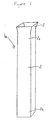
- a rod arrangement 1a comprising a straight, square sectioned rod 2 made of cold-drawn steel is shown in figure 1.
- the rod 2 has a first end 2a and a second end 2b.
- the first end 2a is provided with an integral flared portion 3 formed by upset forging.
- FIG. 1 One portion 5 of a clamping member 12 of the present invention is shown in figures 2 and 3.
- the portion 5 has a central portion 6 with four channel shaped limbs 7 extending therefrom.
- the central portion 6 is provided with a central aperture 8.
- Figure 3 shows the way in which the channel shaped limbs 7 are canted away from the plane of the central portion 6 in the direction in which the side walls 7a extend at an angle of 4°-5°.
- the portion 5 of the clamping member 12 is formed as a pressing and the aperture 8 is added in the same step.
- the portion 5 is formed from mild steel.
- a decorative cover 9 which can optionally be secured to the portion 5 of the clamping member by means of a hardened steel bush insert (not shown) to give a unitary structure is shown in figures 4 and 5.
- FIG. 6a, 6b and 7. An alternative decorative cover 19 is shown in Figures 6a, 6b and 7.
- the cover 19 is formed from two parts 20, 21 which are joined together around the clamping member 12 by corresponding male 22 and female 23 connecting portions.
- the portions 20 and 21 are plastic mouldings.
- FIG 8 Two separate portions 5 secured together to form a clamping member 12 of the present invention are shown in figure 8.
- the two portions 5 are held together by a round headed bolt 10 which has no slot or recess to aid turning.
- the bolt 10 is made from high carbon alloy steel and is heat-treated to make drilling out difficult.
- the bolt 10 engages a hexagonal headed nut 11.
- the head of the nut shears off at a predetermined torque level, which leaves a threaded annulus and makes removal impossible.
- the centre of the portion 5 of the clamping member 12 is depressed to reduce access to the round-headed nut 11.
- Figure 9 shows the way in which four rod arrangements 1a comprising straight rods 2 are secured together by a clamping member 12.
- the straight rods 2 are held at right angles to each other within the two portions 5 of the clamping member 12 which are secured by bolt 10 and nut 11.
- the ends 2a of the rods are provided with flared portions 3 which are received within the clamping member 12 and result in the rods 2 being securely held in the clamping member 12 even on the application of considerable force.
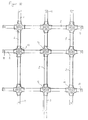
- FIG. 10 A security grille built up from the system of Figure 9 having holes 13 for securing the grille to a portion of a building to cover a door or a window by the use of appropriate fastening means such as screws is shown in Figure 10.
- Figure 11 shows the direction of the forces created over the grille of the present invention when it is secured to portions of a building on all four sides and a load is applied at right angles to the plane of the grille.
- Application of a load at right angles forces the rods to go into tension and pull away from the clamping members.
- the rod arrangements are then positively held at both their ends resulting in a strong and rigid structure with the clamping members having increased hold on the rod arrangements owing to the flared portions of the rod arrangements engaging the clamping members.
Landscapes
- Engineering & Computer Science (AREA)
- Structural Engineering (AREA)
- Architecture (AREA)
- Civil Engineering (AREA)
- Connection Of Plates (AREA)
- Clamps And Clips (AREA)
Applications Claiming Priority (2)
| Application Number | Priority Date | Filing Date | Title |
|---|---|---|---|
| GB0021034 | 2000-08-26 | ||
| GBGB0021034.4A GB0021034D0 (en) | 2000-08-26 | 2000-08-26 | Improved grille systems |
Publications (2)
| Publication Number | Publication Date |
|---|---|
| EP1182318A2 true EP1182318A2 (de) | 2002-02-27 |
| EP1182318A3 EP1182318A3 (de) | 2003-01-22 |
Family
ID=9898346
Family Applications (1)
| Application Number | Title | Priority Date | Filing Date |
|---|---|---|---|
| EP01307283A Withdrawn EP1182318A3 (de) | 2000-08-26 | 2001-08-24 | Verbesserte Rostsysteme |
Country Status (3)
| Country | Link |
|---|---|
| US (1) | US6612086B2 (de) |
| EP (1) | EP1182318A3 (de) |
| GB (1) | GB0021034D0 (de) |
Cited By (4)
| Publication number | Priority date | Publication date | Assignee | Title |
|---|---|---|---|---|
| RU2387781C1 (ru) * | 2009-03-13 | 2010-04-27 | Герман Анатольевич Смирнов | Защитная решетчатая конструкция с декоративными накладками |
| ES2372140A1 (es) * | 2009-09-04 | 2012-01-16 | María José Aguayo Guerrero | Elemento de recubrimiento para rejas. |
| RU2546440C2 (ru) * | 2013-05-29 | 2015-04-10 | Владимир Иванович Рубцов | Способ получения декоративно-прикладных изделий из профильных труб и изделия, полученные указанным способом |
| RU2546439C2 (ru) * | 2013-05-29 | 2015-04-10 | Владимир Иванович Рубцов | Декоративно-прикладное изделие с декоративными защитными накладками |
Families Citing this family (8)
| Publication number | Priority date | Publication date | Assignee | Title |
|---|---|---|---|---|
| US20050005549A1 (en) * | 2003-05-30 | 2005-01-13 | Peter Daniel W. | Flexible tile wall system |
| WO2008070673A2 (en) * | 2006-12-04 | 2008-06-12 | Nanonexus, Inc. | Construction structures and manufacturing processes for integrated circuit wafer probe card assemblies |
| US20060066235A1 (en) * | 2004-09-27 | 2006-03-30 | Brody Thomas P | Receptacles for inkjet deposited PLED/OLED devices and method of making the same |
| US7954296B2 (en) * | 2009-03-20 | 2011-06-07 | Dennis John Newland | Radial tetrahedral modular structures |
| US9049956B2 (en) * | 2009-10-07 | 2015-06-09 | Weber-Stephen Products Co. | Rigid grill structure |
| USD639459S1 (en) * | 2010-02-08 | 2011-06-07 | 3Form, Inc. | Overlapping panel element assembly |
| TWM525113U (zh) * | 2016-04-15 | 2016-07-11 | Cheng-Jie Lin | 組合用具及其連結裝置 |
| US10982699B2 (en) * | 2017-05-08 | 2021-04-20 | Steve Bright | Modular frame assembly |
Citations (1)
| Publication number | Priority date | Publication date | Assignee | Title |
|---|---|---|---|---|
| GB2206916A (en) | 1987-06-26 | 1989-01-18 | Alan David Pitt | Security grille |
Family Cites Families (6)
| Publication number | Priority date | Publication date | Assignee | Title |
|---|---|---|---|---|
| US4723388A (en) * | 1985-04-26 | 1988-02-09 | Mansion Industries, Inc. | Easily formable grid for windows and the like |
| US4714370A (en) * | 1986-11-06 | 1987-12-22 | Chen Geng Nong | Commodity shelf adaptors |
| GB2200708B (en) * | 1987-02-02 | 1991-01-02 | Sutcliffe Group Ltd | Node member for use in building a geodesic structure |
| USD357544S (en) * | 1992-03-02 | 1995-04-18 | Daw Technologies, Inc. | Intersectional casting for ceiling grid support system |
| USD380054S (en) * | 1995-07-21 | 1997-06-17 | Littlejohn Bradley S | Connector and spacer for window false muntins |
| EP0761924A1 (de) * | 1995-08-25 | 1997-03-12 | Francisco Fernandez Iglesias | Herstellungsverfahren für Sprossengitter |
-
2000
- 2000-08-26 GB GBGB0021034.4A patent/GB0021034D0/en not_active Ceased
-
2001
- 2001-08-24 EP EP01307283A patent/EP1182318A3/de not_active Withdrawn
- 2001-08-24 US US09/939,395 patent/US6612086B2/en not_active Expired - Fee Related
Patent Citations (1)
| Publication number | Priority date | Publication date | Assignee | Title |
|---|---|---|---|---|
| GB2206916A (en) | 1987-06-26 | 1989-01-18 | Alan David Pitt | Security grille |
Cited By (5)
| Publication number | Priority date | Publication date | Assignee | Title |
|---|---|---|---|---|
| RU2387781C1 (ru) * | 2009-03-13 | 2010-04-27 | Герман Анатольевич Смирнов | Защитная решетчатая конструкция с декоративными накладками |
| WO2010104417A3 (ru) * | 2009-03-13 | 2010-11-18 | Smirnov German Anatolievich | Защитная решетчатая конструкция с декоративными накладками |
| ES2372140A1 (es) * | 2009-09-04 | 2012-01-16 | María José Aguayo Guerrero | Elemento de recubrimiento para rejas. |
| RU2546440C2 (ru) * | 2013-05-29 | 2015-04-10 | Владимир Иванович Рубцов | Способ получения декоративно-прикладных изделий из профильных труб и изделия, полученные указанным способом |
| RU2546439C2 (ru) * | 2013-05-29 | 2015-04-10 | Владимир Иванович Рубцов | Декоративно-прикладное изделие с декоративными защитными накладками |
Also Published As
| Publication number | Publication date |
|---|---|
| US6612086B2 (en) | 2003-09-02 |
| GB0021034D0 (en) | 2000-10-11 |
| US20020046533A1 (en) | 2002-04-25 |
| EP1182318A3 (de) | 2003-01-22 |
Similar Documents
| Publication | Publication Date | Title |
|---|---|---|
| US6612086B2 (en) | Grille systems | |
| EP0671581B1 (de) | Befestigungsvorrichtung zur Befestigung von Rohren oder dergleichen Gegenständen | |
| US4881354A (en) | Security grille and manufacturing method | |
| EP2756238B1 (de) | Vorrichtung zur befestigung einer montageschiene an einem dachhaken | |
| DE8518780U1 (de) | Verbindungselement für Rohre | |
| EP2253902B1 (de) | Bauteilesatz für die Montage von Solarmodulen auf einem Dach | |
| US5133123A (en) | Security gratings and methods of making bars therefor | |
| EP2093434B1 (de) | Knotenverbinder | |
| EP2194216A1 (de) | Gitterelement, Verfahren zur Herstellung eines Gitterelements und Zaunsystem | |
| EP1775416B1 (de) | Befestigungssystem für einen Aufsatzrollladenkasten | |
| EP1706652A1 (de) | Verbindungsvorrichtung für zwei strangartige hohlprofile und verfahren zu deren herstellung | |
| WO2019084080A1 (en) | CONNECTION FITTINGS FOR A TRANSPORTABLE SHELTER | |
| EP3910125B1 (de) | Tragkonstruktion zur abhängung mindestens eines schallabsorbers von einer decke, system zur verbesserung der akustik in einem raum | |
| EP0947151A2 (de) | Regal | |
| EP1548200B1 (de) | Pfosten-Riegel-Fassade | |
| EP0963496B1 (de) | Fassaden-befestigungsvorrichtung | |
| DE19621098C2 (de) | Gelenkverbindung | |
| EP0967342A2 (de) | Fassadenprofil | |
| WO2020083821A1 (de) | Gerüststiel-anschlussrosette mit hohlprägungen bei reduzierter nenndicke sowie gerüstbaugruppe | |
| EP1199481A1 (de) | Querverbindung von Profilstäben | |
| AT510059B1 (de) | Verbindungsvorrichtung zum verbinden von miteinander zu verbindenden gegenständen sowie konstruktionselement und verwendung | |
| JPH0135043Y2 (de) | ||
| JP2793761B2 (ja) | フック金物およびその製造方法 | |
| US5890561A (en) | Connection between a ladder side rail and a hinged arm of a ladder hinge | |
| EP4270695A1 (de) | Befestigungsklammer für ein langelement, insbesondere ein kabeltragsystem sowie kabeltragsystem mit einer solchen befestigungsklammer |
Legal Events
| Date | Code | Title | Description |
|---|---|---|---|
| PUAI | Public reference made under article 153(3) epc to a published international application that has entered the european phase |
Free format text: ORIGINAL CODE: 0009012 |
|
| AK | Designated contracting states |
Kind code of ref document: A2 Designated state(s): AT BE CH CY DE DK ES FI FR GB GR IE IT LI LU MC NL PT SE TR |
|
| AX | Request for extension of the european patent |
Free format text: AL;LT;LV;MK;RO;SI |
|
| PUAL | Search report despatched |
Free format text: ORIGINAL CODE: 0009013 |
|
| AK | Designated contracting states |
Kind code of ref document: A3 Designated state(s): AT BE CH CY DE DK ES FI FR GB GR IE IT LI LU MC NL PT SE TR |
|
| AX | Request for extension of the european patent |
Free format text: AL;LT;LV;MK;RO;SI |
|
| 17P | Request for examination filed |
Effective date: 20030721 |
|
| AKX | Designation fees paid |
Designated state(s): AT BE CH CY DE DK ES FI FR GB GR IE IT LI LU MC NL PT SE TR |
|
| 17Q | First examination report despatched |
Effective date: 20070726 |
|
| STAA | Information on the status of an ep patent application or granted ep patent |
Free format text: STATUS: THE APPLICATION IS DEEMED TO BE WITHDRAWN |
|
| 18D | Application deemed to be withdrawn |
Effective date: 20071206 |