EP1182003A2 - Machine-outil et procédé d'opération d'une machine-outil - Google Patents
Machine-outil et procédé d'opération d'une machine-outil Download PDFInfo
- Publication number
- EP1182003A2 EP1182003A2 EP01118216A EP01118216A EP1182003A2 EP 1182003 A2 EP1182003 A2 EP 1182003A2 EP 01118216 A EP01118216 A EP 01118216A EP 01118216 A EP01118216 A EP 01118216A EP 1182003 A2 EP1182003 A2 EP 1182003A2
- Authority
- EP
- European Patent Office
- Prior art keywords
- machine
- functional unit
- relative position
- machine frame
- relative
- Prior art date
- Legal status (The legal status is an assumption and is not a legal conclusion. Google has not performed a legal analysis and makes no representation as to the accuracy of the status listed.)
- Granted
Links
Images


Classifications
-
- B—PERFORMING OPERATIONS; TRANSPORTING
- B23—MACHINE TOOLS; METAL-WORKING NOT OTHERWISE PROVIDED FOR
- B23Q—DETAILS, COMPONENTS, OR ACCESSORIES FOR MACHINE TOOLS, e.g. ARRANGEMENTS FOR COPYING OR CONTROLLING; MACHINE TOOLS IN GENERAL CHARACTERISED BY THE CONSTRUCTION OF PARTICULAR DETAILS OR COMPONENTS; COMBINATIONS OR ASSOCIATIONS OF METAL-WORKING MACHINES, NOT DIRECTED TO A PARTICULAR RESULT
- B23Q17/00—Arrangements for observing, indicating or measuring on machine tools
-
- B—PERFORMING OPERATIONS; TRANSPORTING
- B23—MACHINE TOOLS; METAL-WORKING NOT OTHERWISE PROVIDED FOR
- B23Q—DETAILS, COMPONENTS, OR ACCESSORIES FOR MACHINE TOOLS, e.g. ARRANGEMENTS FOR COPYING OR CONTROLLING; MACHINE TOOLS IN GENERAL CHARACTERISED BY THE CONSTRUCTION OF PARTICULAR DETAILS OR COMPONENTS; COMBINATIONS OR ASSOCIATIONS OF METAL-WORKING MACHINES, NOT DIRECTED TO A PARTICULAR RESULT
- B23Q11/00—Accessories fitted to machine tools for keeping tools or parts of the machine in good working condition or for cooling work; Safety devices specially combined with or arranged in, or specially adapted for use in connection with, machine tools
- B23Q11/04—Arrangements preventing overload of tools, e.g. restricting load
-
- B—PERFORMING OPERATIONS; TRANSPORTING
- B23—MACHINE TOOLS; METAL-WORKING NOT OTHERWISE PROVIDED FOR
- B23Q—DETAILS, COMPONENTS, OR ACCESSORIES FOR MACHINE TOOLS, e.g. ARRANGEMENTS FOR COPYING OR CONTROLLING; MACHINE TOOLS IN GENERAL CHARACTERISED BY THE CONSTRUCTION OF PARTICULAR DETAILS OR COMPONENTS; COMBINATIONS OR ASSOCIATIONS OF METAL-WORKING MACHINES, NOT DIRECTED TO A PARTICULAR RESULT
- B23Q5/00—Driving or feeding mechanisms; Control arrangements therefor
- B23Q5/54—Arrangements or details not restricted to group B23Q5/02 or group B23Q5/22 respectively, e.g. control handles
- B23Q5/58—Safety devices
Definitions
- the invention relates to a machine, in particular a machine tool comprising a machine frame and at least one in at least one Alignment direction defines functional unit positioned to the machine frame, which is releasable via a connection point and to prevent a Movement in at least one evasive direction with the Machine frame is connected.
- the functional unit is deliberately detachable and non-positively connected to the machine frame, for example in the case collisions or other unexpected events open up that the functional unit by a relative movement to Machine frame is not or not significantly damaged.
- the invention is therefore based on the object of a machine of the generic type Art to improve in that at no longer defined to Machine frame extending alignment direction of the functional unit, if possible is easily recognizable and as easy to fix as possible.
- This task is performed on a machine of the type described in the introduction solved according to the invention in that in the area of the connection point at least two in the direction of the alignment at a distance from each other arranged measuring points by means of a displacement sensor in the avoidance direction a relative position between the functional unit and the machine frame is detectable and that the measuring sensor an evaluation device and Visualization device are assigned, with which current, by which Relative positions detected can be visualized.
- the solution according to the invention also opens up the possibility of machine in operation to record the current relative position.
- a particularly advantageous solution provides that the current relative position during a production cycle, preferably even during workpiece machining, is detectable.
- Displacement sensor detects the relative position of a housing of the functional unit, since detection on the housing of the functional unit is possible at any time, without interfering with workpiece machining or others Production steps are carried out.
- the displacement sensor is arranged on the machine frame side and the relative position of the functional unit with respect to the machine frame. This allows the displacement sensor always be arranged on the machine frame side, and it is for example possible in a simple manner, as is the visualization device to be provided on the machine frame side.
- Such reference positions can be recorded in a wide variety of ways. For example, it would be conceivable to always use the respective reference position to use the relative position preceding the current relative position.
- the relative position with accuracy-optimized Alignment of the functional unit is used relative to the machine frame.
- the relative position at startup is preferably the reference position the machine tool can be detected.
- the reference position is one-off optimally aligned functional unit can be recorded and used for later evaluation the relative positions can be stored.
- the visualization device With regard to the type of display of the relative position by the visualization device the most different possibilities are conceivable. For example it would be conceivable to design the visualization device so that it unites Numerical value for the respective reference position and a numerical value for the shows the relative position.
- the visualization device the difference between the relative position and displays the reference position.
- Such a display can either be numerical, for example by specifying it of numbers, or also graphically, for example using bar charts respectively.
- an inventive Machine provides a mobile displacement sensor, with which not only in Area of the junction measurements for the exact alignment of several Functional units can be performed, but also the detection of the relative positions for example two functional units relative to each other or relative to the machine frame.
- a particularly useful solution in which the mobile displacement sensor can be used advantageously, provides that with the mobile displacement sensor a relative position between the machine frame or one this seated functional unit on the one hand and a machine control the machine tool controllable functional unit on the other hand is feasible.
- the object of the invention is also achieved by a Method for detecting the exact position of a functional unit of a Machine tool solved relative to the machine frame, the functional unit defined in at least one direction of alignment to the machine frame is positioned and releasable via a connection point and to prevent a movement in at least one evasive direction is connected to the machine frame and also according to the invention in Area of the connection point at at least two in the alignment direction in A current relative position at a distance from each other detected between the functional unit and the machine frame and is then visualized.
- This solution also has the advantage that in all possible operating states the machine can detect the relative position.
- the relative position is detected during a production run, whereby the production run does not have to be interrupted, but Such a detection of the relative position parallel to the production run between machine frame and functional unit is possible.
- Another alternative is to set the current relative position according to To determine machining cycles so that, for example, at the end of each Machining cycle or at the beginning of the next machining cycle determines the current relative position and thus the machine with regard to their accuracy is checked.
- Another way to determine the current relative position if possible rarely to be done is that the current relative position after a collision is determined since, as a rule, it can only be assumed in the event of a collision is that the existing relative position has changed since it is essential for the precision of a machine that it is so rigid is that for example the machining of a workpiece and in particular machining the maximum possible workpiece no negative Has consequences on the accuracy of the machine.
- a particularly advantageous solution provides that the difference between the reference position and the current relative position determined and displayed is so that the operator of the machine is not familiar with the individual numerical values must grapple with, but is immediately shown, which difference in accuracy affects production at any given time could.
- a further advantageous possibility of using the concept according to the invention can be seen in the fact that the current relative position in the course of a Adjustment of the functional unit is determined and the adjustment accordingly the comparison with the reference position is performed so that the the method according to the invention can be used advantageously, if possible, a functional unit misaligned relative to the machine frame should be adjusted again.
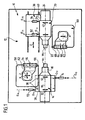
- An embodiment of a machine according to the invention for example a machine tool shown in Figs. 1 and 2 includes one as a whole 10 designated machine frame with a support body 12 on which a first spindle housing 14 of a first one rotatable about a spindle axis 18 Working spindle 16 is arranged.
- a second spindle housing 20 is on the carrier body 12 arranged second working spindle 22 which is rotatable about a spindle axis 24 is, wherein the spindle axes 18 and 24 are aligned with each other are.
- the first is seated at a first connection point 26
- the contact surface 34 being used to produce a non-positive connection is clamped against the mounting surface 30 by means of clamping elements 36, so that the spindle housing 14 with the bearing surface 34 relative to the mounting surface 30 for example in the event of a machine collision in the direction of the avoidance direction 32 overcoming the positive connection between the Mounting surface 30 and the support surface 34 is displaceable.
- the second spindle housing 20 is in turn arranged on a slide 38, which is controlled in a Z direction relative to the carrier body 12 is movable.
- the carriage 38 in turn carries a mounting surface 40 on which the Spindle housing 20 at a second connection point 46 through its foot 21 rests with a bearing surface 44 and against movement in one transverse to the spindle axis 24 and parallel to the mounting surface 40
- Evasion direction 42 is fixed non-positively, in the event of a machine collision the force acting on the spindle 22 and thus on the spindle housing 20 to overcome the frictional fixation of the bearing surface 44 leads on the mounting surface 40 and thus the entire spindle housing 20th is displaceable relative to the carriage 38 in the avoidance direction 42, the In principle, avoidance direction 42 can be oriented as desired.
- a first tool slide 50 is arranged on the carrier body 12, which in an X direction perpendicular to the spindle axis 18 and in one Z direction parallel to the spindle axis 18 relative to the carrier body 12 in is known to be movable.
- a first tool carrier 52 Arranged on the first tool slide 50 is a first tool carrier 52 which, for example, has a turret 54, in the tool holders 56 of which tools 58 can be used, for example for machining a workpiece W 1 which is received in the first spindle 16 and rotates about the spindle axis 18 ' to be able to.
- the second spindle housing 20 is assigned a second tool slide 60, which can be moved at least in the X direction perpendicular to the spindle axis 24 and in turn carries a second tool carrier 62 which is provided with a turret 64, in the tool holders 66 of which tools 68 for machining a tool the second spindle 22 received workpiece W 2 is arranged.
- the entire spindle housing 20 together with the slide 38 can preferably be moved in the Z direction, for example in order to remove the workpiece W 1 on its machined side from the first spindle 16 and then to machine a rear side on this workpiece, which is referred to as W 2 .
- a programmable machine controller designated as a whole by 70 70 provided.
- first spindle axis 18 is displaced relative to the machine frame 10 and is also no longer aligned with the second spindle axis 24, so that the further machining of the workpieces W 1 and / or W 2 leads to a loss of accuracy, since the control 70 removes the tool slide 50 and controls the tool carrier 52 in the same way as if the spindle axis 18 were in their original position.
- the first spindle housing 14 has two, for example Position transducers 72 and 74 are assigned, which are mounted stationary on the carrier body 12 and are able with their probes 73 and 75, respectively, at measuring locations O 11 and O 12 , for example in perpendicular to the spindle axis 18, but in planes running parallel to this E 11 and E 12 lie to detect a position of the foot 15 of the first spindle housing 14 relative to the carrier body 12.
- Position transducers 72 and 74 are assigned, which are mounted stationary on the carrier body 12 and are able with their probes 73 and 75, respectively, at measuring locations O 11 and O 12 , for example in perpendicular to the spindle axis 18, but in planes running parallel to this E 11 and E 12 lie to detect a position of the foot 15 of the first spindle housing 14 relative to the carrier body 12.
- each of the displacement sensors 72 and 74 connected to an A / D converter 82 and 84, which in turn corresponds to a controller designated as a whole by 86, which is able to measure those measured by the displacement sensors 72 and 74 Detect positions in an ideally adjusted machine tool and in one Store memory 88.
- the controller 86 can be integrated into the machine controller 76, she can also work completely separately from it.
- the relative position of the first headstock 14 with respect to the Machine frame 10 detected and documented in the memory.
- the relative position of the first spindle housing 14 with respect to the machine frame 10 can thus be continuously tracked, for example, even during a machining process of a workpiece W 1 or W 2 .
- the controller 86 is a visualization device 90, for example a Screen assigned, which is able, for example, the original measured by the displacement sensors 72 and 74 as a reference position Measured value and at the same time that corresponding to the current reference position Measurement: display.
- the first spindle housing 14 For example, only a displacement of the first spindle housing 14 is relative to the machine frame 10, there is the possibility while maintaining and constant continuation of the measurement with the displacement sensors 72 and 74 and loosening the for the positive connection between the Mounting surface 30 and the support surface 34 responsible clamping elements 36 the first spindle housing 14 relative to the machine frame again adjust so that the displacement sensors 72 and 74 show the values that are as possible largely the one originally used by displacement sensors 72 and 74 detected values correspond to those of controller 86 in memory 88 were filed.
- the visualization device 90 only the difference between the original, corresponding to the adjusted state Measured value and the current, d. H. after the collision shifted state corresponding measured value, to display for the Operator the degree of misalignment of the first headstock 14 relative to To design machine frame 10 clearly recognizable.
- the second spindle housing 20 is also assigned two displacement transducers 92 and 94, which are mounted stationary on the slide 38 and with their probes 93 and 95 at measuring locations O 21 and O 22 , which are in planes E 21 and E 22 running perpendicular to the spindle axis 24 lie against the foot 21 of the second spindle housing 20 and thereby detect the position of the second spindle housing 20 relative to the slide 38 in the avoidance direction 42.
- the detection of the relative position of the second spindle housing 20 based on the avoidance direction 42 also an exact detection of the relative position of this second spindle housing 20 relative to the support body 12 and thus to the machine frame 10.
- the displacement sensors 92 and 94 are also equipped with analog-digital converters 102 and 104, which in turn are connected to the controller 86 in Are interacting, so that the controller 86 in the same way as in Described in connection with the displacement sensors 72 and 74, in the Is, the exact relative position of the spindle housing 20 in the evasive direction 42 to be detected when the spindle housing 20 is exactly relative to the Machine frame 10 and also aligned exactly relative to the spindle housing 14 is and is also capable of the relative position of the spindle housing 20 each currently during the operation of the machine tool and especially after a collision and also when realigning the Detect spindle housing 20 in the manner described.
- the mobile measuring device 110 can be used so that the contact edge 114 on any reference surface, for example an end surface 122 of the first Work spindle 16 or a lateral surface 124 of the first work spindle 16, can be applied, the probe 118 pointing in the measuring direction 120 and thereby in the Is, for example, a position of a machine controller 70 Function group to be recognized on the probe 118.
- any reference surface for example an end surface 122 of the first Work spindle 16 or a lateral surface 124 of the first work spindle 16
- the probe 118 pointing in the measuring direction 120 and thereby in the Is, for example, a position of a machine controller 70 Function group to be recognized on the probe 118.
- the relative position of the first spindle housing can also be used 14 compared to one of the tool carriers 52 or 62 or one of the Check tools 58 or 68.
- a constant voltage source 130 is provided for each of the displacement sensors 72, 74, 92, 94, 116 with a constant operating voltage provided.
Landscapes
- Engineering & Computer Science (AREA)
- Mechanical Engineering (AREA)
- Machine Tool Sensing Apparatuses (AREA)
- Numerical Control (AREA)
Applications Claiming Priority (2)
| Application Number | Priority Date | Filing Date | Title |
|---|---|---|---|
| DE10040019 | 2000-08-16 | ||
| DE2000140019 DE10040019A1 (de) | 2000-08-16 | 2000-08-16 | Maschine und Verfahren zum Betreiben einer Maschine |
Publications (3)
| Publication Number | Publication Date |
|---|---|
| EP1182003A2 true EP1182003A2 (fr) | 2002-02-27 |
| EP1182003A3 EP1182003A3 (fr) | 2002-06-19 |
| EP1182003B1 EP1182003B1 (fr) | 2008-05-28 |
Family
ID=7652615
Family Applications (1)
| Application Number | Title | Priority Date | Filing Date |
|---|---|---|---|
| EP20010118216 Expired - Lifetime EP1182003B1 (fr) | 2000-08-16 | 2001-07-28 | Machine-outil et procédé d'opération d'une machine-outil |
Country Status (2)
| Country | Link |
|---|---|
| EP (1) | EP1182003B1 (fr) |
| DE (2) | DE10040019A1 (fr) |
Cited By (2)
| Publication number | Priority date | Publication date | Assignee | Title |
|---|---|---|---|---|
| CN104959928A (zh) * | 2015-06-12 | 2015-10-07 | 雄华机械(苏州)有限公司 | 一种设有位移监测设备的固定治具 |
| EP3453487A1 (fr) * | 2017-09-12 | 2019-03-13 | Index-Werke GmbH & Co. KG Hahn & Tessky | Procédé de positionnement d'un point central sur un axe géométrique dans une machine-outil |
Families Citing this family (1)
| Publication number | Priority date | Publication date | Assignee | Title |
|---|---|---|---|---|
| CN110877222A (zh) * | 2019-12-09 | 2020-03-13 | 宝鸡市捷龙商贸有限公司 | 一种机电设备加工用定位机构 |
Family Cites Families (6)
| Publication number | Priority date | Publication date | Assignee | Title |
|---|---|---|---|---|
| DE3711434A1 (de) * | 1987-04-04 | 1988-10-13 | Krupp Gmbh | Verfahren zur beruehrungslosen bruch-, verschleiss- und kollisionsueberwachung von werkzeugen |
| SE458965B (sv) * | 1987-10-13 | 1989-05-22 | Sandvik Ab | Kraftgivare foer en verkygsmaskin jaemte en metod att avkaenna krafter som uppstaar vid bearbetning av ett arbetsstycke i en verktygsmaskin |
| US4893532A (en) * | 1988-05-26 | 1990-01-16 | Hardinge Brothers, Inc. | Break away tool element and method of mounting |
| DE4025522A1 (de) * | 1990-08-11 | 1992-02-13 | Wolter Doll Dieter | Verfahren und vorrichtung zur erkennung von bearbeitungsfehlern, insbesondere von schleifmaschinen |
| DE4238338A1 (de) * | 1992-11-13 | 1994-05-19 | Heller Geb Gmbh Maschf | Überwachungseinrichtung für Werkzeuge einer Bearbeitungsmaschine |
| DE4432582C2 (de) * | 1993-09-14 | 1996-05-23 | Werner Dr Ing Kluft | Vorrichtung zur Radialkraftmessung an Zentrierspitzen von Werkzeugmaschinen |
-
2000
- 2000-08-16 DE DE2000140019 patent/DE10040019A1/de not_active Ceased
-
2001
- 2001-07-28 EP EP20010118216 patent/EP1182003B1/fr not_active Expired - Lifetime
- 2001-07-28 DE DE50113996T patent/DE50113996D1/de not_active Expired - Lifetime
Cited By (3)
| Publication number | Priority date | Publication date | Assignee | Title |
|---|---|---|---|---|
| CN104959928A (zh) * | 2015-06-12 | 2015-10-07 | 雄华机械(苏州)有限公司 | 一种设有位移监测设备的固定治具 |
| EP3453487A1 (fr) * | 2017-09-12 | 2019-03-13 | Index-Werke GmbH & Co. KG Hahn & Tessky | Procédé de positionnement d'un point central sur un axe géométrique dans une machine-outil |
| US10788306B2 (en) | 2017-09-12 | 2020-09-29 | Index-Werke Gmbh And Co. Kg Hahn And Tessky | Method for positioning a center point on a geometric axis in a machine tool |
Also Published As
| Publication number | Publication date |
|---|---|
| DE50113996D1 (de) | 2008-07-10 |
| EP1182003A3 (fr) | 2002-06-19 |
| DE10040019A1 (de) | 2002-05-02 |
| EP1182003B1 (fr) | 2008-05-28 |
Similar Documents
| Publication | Publication Date | Title |
|---|---|---|
| DE4495551C2 (de) | Z-Achsen-Antrieb für eine Werkzeugmaschine | |
| EP1027955B1 (fr) | Machine-outil | |
| DE9007812U1 (de) | Mehrspindelmaschine zum Bohren, Fräsen o.dgl. | |
| EP0505787A2 (fr) | Dispositif pour l'ajustage d'une rectifieuse à commande CNC | |
| EP0270721B1 (fr) | Agencement de mesure pour la détermination des dimensions d'un objet selon trois coordonnées | |
| EP0716362B1 (fr) | Méthode et dispositif de surveillance du déplacement d'une partie d'une machine-outil | |
| EP3453487A1 (fr) | Procédé de positionnement d'un point central sur un axe géométrique dans une machine-outil | |
| DE102016121599A1 (de) | Werkzeugmaschine mit Wechseleinrichtung und Kommunikationseinrichtung | |
| EP1180407A1 (fr) | Machine-outil | |
| EP0789221A2 (fr) | Méthode pour mesurer les coordonnées de pièces usinées sur des machines-outils | |
| DE102007019453B4 (de) | Koordinatenmessgerät mit zwei Schlitten auf gemeinsamer Führung | |
| DE4411263C2 (de) | Verfahren zur Überprüfung der Führungsgenauigkeit einer Brennschneidmaschine und Anordnung zur Durchführung des Verfahrens | |
| DE10030087B4 (de) | Verfahren und Vorrichtung zum Vermessen und Bearbeiten von Werkstücken | |
| EP2846966B1 (fr) | Centre de transfert destiné à usiner au moins une pièce par enlèvement de matière, comprenant un système de compensation de position | |
| DE10250326A1 (de) | Werkzeugmaschine und Verfahren zur Justage der Spindelposition dieser Werkzeugmaschine | |
| DE4113543A1 (de) | Vorrichtung zur bearbeitung der kantenraender von plattenfoermigen werkstuecken | |
| DE102020203770A1 (de) | Steuergerät und Werkzeugmaschine | |
| WO2017063636A1 (fr) | Dispositif et procédé d'usinage par laser d'une pièce réalisée sous forme de composant d'armoire de commande | |
| EP1182003B1 (fr) | Machine-outil et procédé d'opération d'une machine-outil | |
| EP3081324A1 (fr) | Tour à poupée mobile comprenant deux axes d'usinage à commande numérique et procédé destiné à usiner des pièces sur un tour a poupée mobile comprenant deux axes d'usinage à commande numérique | |
| DE10061883A1 (de) | Polarkoordinaten-Bohrmaschine mit Bohrer-Vorschubsteuerung | |
| DE3426548C2 (fr) | ||
| DE19936468A1 (de) | Drehmaschine | |
| EP2080584A1 (fr) | Dispositif et procédé destinés au traitement de pièces à usiner | |
| EP0315575A1 (fr) | Procédé et appareil de mesure pour la détermination du diamètre de roulement |
Legal Events
| Date | Code | Title | Description |
|---|---|---|---|
| PUAI | Public reference made under article 153(3) epc to a published international application that has entered the european phase |
Free format text: ORIGINAL CODE: 0009012 |
|
| AK | Designated contracting states |
Kind code of ref document: A2 Designated state(s): AT BE CH CY DE DK ES FI FR GB GR IE IT LI LU MC NL PT SE TR |
|
| AX | Request for extension of the european patent |
Free format text: AL;LT;LV;MK;RO;SI |
|
| PUAL | Search report despatched |
Free format text: ORIGINAL CODE: 0009013 |
|
| AK | Designated contracting states |
Kind code of ref document: A3 Designated state(s): AT BE CH CY DE DK ES FI FR GB GR IE IT LI LU MC NL PT SE TR |
|
| AX | Request for extension of the european patent |
Free format text: AL;LT;LV;MK;RO;SI |
|
| RIC1 | Information provided on ipc code assigned before grant |
Free format text: 7B 23Q 1/01 A, 7B 23Q 15/14 B, 7B 23Q 15/22 B, 7B 23Q 17/22 B, 7B 23Q 3/18 B, 7B 23Q 39/02 B, 7B 23Q 39/04 B, 7B 23Q 11/04 B, 7B 23Q 17/00 B, 7B 23Q 5/58 B |
|
| 17P | Request for examination filed |
Effective date: 20021214 |
|
| AKX | Designation fees paid |
Designated state(s): CH DE ES FR IT LI |
|
| GRAP | Despatch of communication of intention to grant a patent |
Free format text: ORIGINAL CODE: EPIDOSNIGR1 |
|
| GRAS | Grant fee paid |
Free format text: ORIGINAL CODE: EPIDOSNIGR3 |
|
| GRAA | (expected) grant |
Free format text: ORIGINAL CODE: 0009210 |
|
| AK | Designated contracting states |
Kind code of ref document: B1 Designated state(s): CH DE ES FR IT LI |
|
| REG | Reference to a national code |
Ref country code: CH Ref legal event code: EP |
|
| REF | Corresponds to: |
Ref document number: 50113996 Country of ref document: DE Date of ref document: 20080710 Kind code of ref document: P |
|
| REG | Reference to a national code |
Ref country code: CH Ref legal event code: NV Representative=s name: KIRKER & CIE S.A. |
|
| PG25 | Lapsed in a contracting state [announced via postgrant information from national office to epo] |
Ref country code: ES Free format text: LAPSE BECAUSE OF FAILURE TO SUBMIT A TRANSLATION OF THE DESCRIPTION OR TO PAY THE FEE WITHIN THE PRESCRIBED TIME-LIMIT Effective date: 20080908 |
|
| PLBE | No opposition filed within time limit |
Free format text: ORIGINAL CODE: 0009261 |
|
| STAA | Information on the status of an ep patent application or granted ep patent |
Free format text: STATUS: NO OPPOSITION FILED WITHIN TIME LIMIT |
|
| 26N | No opposition filed |
Effective date: 20090303 |
|
| PGFP | Annual fee paid to national office [announced via postgrant information from national office to epo] |
Ref country code: CH Payment date: 20130712 Year of fee payment: 13 Ref country code: DE Payment date: 20130828 Year of fee payment: 13 |
|
| PGFP | Annual fee paid to national office [announced via postgrant information from national office to epo] |
Ref country code: FR Payment date: 20130724 Year of fee payment: 13 |
|
| PGFP | Annual fee paid to national office [announced via postgrant information from national office to epo] |
Ref country code: IT Payment date: 20130718 Year of fee payment: 13 |
|
| REG | Reference to a national code |
Ref country code: DE Ref legal event code: R119 Ref document number: 50113996 Country of ref document: DE |
|
| REG | Reference to a national code |
Ref country code: CH Ref legal event code: PL |
|
| REG | Reference to a national code |
Ref country code: FR Ref legal event code: ST Effective date: 20150331 |
|
| PG25 | Lapsed in a contracting state [announced via postgrant information from national office to epo] |
Ref country code: CH Free format text: LAPSE BECAUSE OF NON-PAYMENT OF DUE FEES Effective date: 20140731 Ref country code: DE Free format text: LAPSE BECAUSE OF NON-PAYMENT OF DUE FEES Effective date: 20150203 Ref country code: LI Free format text: LAPSE BECAUSE OF NON-PAYMENT OF DUE FEES Effective date: 20140731 Ref country code: IT Free format text: LAPSE BECAUSE OF NON-PAYMENT OF DUE FEES Effective date: 20140728 |
|
| REG | Reference to a national code |
Ref country code: DE Ref legal event code: R119 Ref document number: 50113996 Country of ref document: DE Effective date: 20150203 |
|
| PG25 | Lapsed in a contracting state [announced via postgrant information from national office to epo] |
Ref country code: FR Free format text: LAPSE BECAUSE OF NON-PAYMENT OF DUE FEES Effective date: 20140731 |