EP1180812A2 - Brennstoffzellensystem - Google Patents
Brennstoffzellensystem Download PDFInfo
- Publication number
- EP1180812A2 EP1180812A2 EP01119534A EP01119534A EP1180812A2 EP 1180812 A2 EP1180812 A2 EP 1180812A2 EP 01119534 A EP01119534 A EP 01119534A EP 01119534 A EP01119534 A EP 01119534A EP 1180812 A2 EP1180812 A2 EP 1180812A2
- Authority
- EP
- European Patent Office
- Prior art keywords
- fuel cell
- cell system
- media
- cathode
- anode
- Prior art date
- Legal status (The legal status is an assumption and is not a legal conclusion. Google has not performed a legal analysis and makes no representation as to the accuracy of the status listed.)
- Granted
Links
Images
Classifications
-
- H—ELECTRICITY
- H01—ELECTRIC ELEMENTS
- H01M—PROCESSES OR MEANS, e.g. BATTERIES, FOR THE DIRECT CONVERSION OF CHEMICAL ENERGY INTO ELECTRICAL ENERGY
- H01M8/00—Fuel cells; Manufacture thereof
- H01M8/04—Auxiliary arrangements, e.g. for control of pressure or for circulation of fluids
- H01M8/04082—Arrangements for control of reactant parameters, e.g. pressure or concentration
- H01M8/04089—Arrangements for control of reactant parameters, e.g. pressure or concentration of gaseous reactants
- H01M8/04119—Arrangements for control of reactant parameters, e.g. pressure or concentration of gaseous reactants with simultaneous supply or evacuation of electrolyte; Humidifying or dehumidifying
- H01M8/04156—Arrangements for control of reactant parameters, e.g. pressure or concentration of gaseous reactants with simultaneous supply or evacuation of electrolyte; Humidifying or dehumidifying with product water removal
-
- H—ELECTRICITY
- H01—ELECTRIC ELEMENTS
- H01M—PROCESSES OR MEANS, e.g. BATTERIES, FOR THE DIRECT CONVERSION OF CHEMICAL ENERGY INTO ELECTRICAL ENERGY
- H01M8/00—Fuel cells; Manufacture thereof
- H01M8/10—Fuel cells with solid electrolytes
- H01M2008/1095—Fuel cells with polymeric electrolytes
-
- H—ELECTRICITY
- H01—ELECTRIC ELEMENTS
- H01M—PROCESSES OR MEANS, e.g. BATTERIES, FOR THE DIRECT CONVERSION OF CHEMICAL ENERGY INTO ELECTRICAL ENERGY
- H01M8/00—Fuel cells; Manufacture thereof
- H01M8/04—Auxiliary arrangements, e.g. for control of pressure or for circulation of fluids
- H01M8/04082—Arrangements for control of reactant parameters, e.g. pressure or concentration
- H01M8/04089—Arrangements for control of reactant parameters, e.g. pressure or concentration of gaseous reactants
- H01M8/04119—Arrangements for control of reactant parameters, e.g. pressure or concentration of gaseous reactants with simultaneous supply or evacuation of electrolyte; Humidifying or dehumidifying
- H01M8/04156—Arrangements for control of reactant parameters, e.g. pressure or concentration of gaseous reactants with simultaneous supply or evacuation of electrolyte; Humidifying or dehumidifying with product water removal
- H01M8/04164—Arrangements for control of reactant parameters, e.g. pressure or concentration of gaseous reactants with simultaneous supply or evacuation of electrolyte; Humidifying or dehumidifying with product water removal by condensers, gas-liquid separators or filters
-
- H—ELECTRICITY
- H01—ELECTRIC ELEMENTS
- H01M—PROCESSES OR MEANS, e.g. BATTERIES, FOR THE DIRECT CONVERSION OF CHEMICAL ENERGY INTO ELECTRICAL ENERGY
- H01M8/00—Fuel cells; Manufacture thereof
- H01M8/04—Auxiliary arrangements, e.g. for control of pressure or for circulation of fluids
- H01M8/04082—Arrangements for control of reactant parameters, e.g. pressure or concentration
- H01M8/04089—Arrangements for control of reactant parameters, e.g. pressure or concentration of gaseous reactants
- H01M8/04119—Arrangements for control of reactant parameters, e.g. pressure or concentration of gaseous reactants with simultaneous supply or evacuation of electrolyte; Humidifying or dehumidifying
- H01M8/04156—Arrangements for control of reactant parameters, e.g. pressure or concentration of gaseous reactants with simultaneous supply or evacuation of electrolyte; Humidifying or dehumidifying with product water removal
- H01M8/04179—Arrangements for control of reactant parameters, e.g. pressure or concentration of gaseous reactants with simultaneous supply or evacuation of electrolyte; Humidifying or dehumidifying with product water removal by purging or increasing flow or pressure of reactants
-
- Y—GENERAL TAGGING OF NEW TECHNOLOGICAL DEVELOPMENTS; GENERAL TAGGING OF CROSS-SECTIONAL TECHNOLOGIES SPANNING OVER SEVERAL SECTIONS OF THE IPC; TECHNICAL SUBJECTS COVERED BY FORMER USPC CROSS-REFERENCE ART COLLECTIONS [XRACs] AND DIGESTS
- Y02—TECHNOLOGIES OR APPLICATIONS FOR MITIGATION OR ADAPTATION AGAINST CLIMATE CHANGE
- Y02E—REDUCTION OF GREENHOUSE GAS [GHG] EMISSIONS, RELATED TO ENERGY GENERATION, TRANSMISSION OR DISTRIBUTION
- Y02E60/00—Enabling technologies; Technologies with a potential or indirect contribution to GHG emissions mitigation
- Y02E60/30—Hydrogen technology
- Y02E60/50—Fuel cells
Definitions
- the invention relates to a fuel cell system according to the General term of the independent claim.
- DE 195 31 852 C1 describes a fuel cell system known in which a water separator for removing Product water is provided.
- the water separator has one Control device in the form of a valve, the one automatic drainage of the water separator.
- the invention is based on the object Specify fuel cell system in which the water separation is improved.
- the advantage is that the media flow in every load range with an optimal flow rate and / or with optimal flow path in the drainage system can be, so that the drainage device has a high Efficiency achieved.
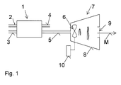
- Fig. 1 is a schematic diagram as a section of a preferred fuel cell system shown.
- a fuel cell system has at least one Fuel cell unit 1.
- the fuel cell unit 1 has anode-side media feed means 2 for feeding a Fuel, e.g. Hydrogen gas, and anode side Media discharge means 4 for discharging an anode outflow, Media supply means 3 on the cathode side for supplying a Oxidizing agent, e.g. Oxygen or air, and Media discharge means 5 on the cathode side for discharging a Cathode outflow, such as water and oxygen.
- a drainage device 7 Downstream of the Fuel cell unit 1 is a drainage device 7 arranged to remove water from a media stream M.
- the drainage device 7 is preferably a Water separator.
- the drainage device 7 according to the invention can be used advantageously in the system where water comes from a media stream is to be removed. You can upstream or be provided downstream of the fuel cell unit 1.
- a water separator is designed so that at a certain operating point one for the water separator optimal deposition rate can be achieved. This can be about a certain flow rate of the water to be drained Medium.
- the efficiency of the Drainage device i.e. the deposition rate is included traditionally a function of media speed.
- media speed itself depends on the load the fuel cell.
- the media speed is at partial load low, high at full load. This results in a total Deposition rate of the drainage system, that of the load state is dependent on the fuel cell.
- the Separation rate is now set independently of the load become; the amount of water separated can be about Speed of a fan wheel can be determined.
- the drive means 10 drive the fan 6 depending on the load.
- media throughput is lower than at full load.
- the fan is preferably driven so that with each Load range of the fuel cell system one Flow rate of the media flow M can be achieved can, in which the water separator has a high efficiency having. It is advantageous if the flow rate constant, as independent as possible of the load on the Fuel cell, can be adjusted.
- the wet one Media flow M can then always at the speed in the Water separators are guided, for which this is optimized and where it has its optimal efficiency and its optimal Deposition rate.
- the fan 6 is preferably operated by an electric motor driven, depending on the load on the Fuel cell unit the speed of the fan wheel of the fan 6 changes. At high load, at which the flow velocity of the media flow M is high, the speed may be lower than at low load, so that the media flow M in is accelerated substantially at partial load.
- the housing 8 can be used as Cooling surface for condensing water out of the media flow M be provided.
- the drainage device 7 is expediently in the Media discharge means 5 arranged on the cathode and / or also in the anode downstream and / or in a flow path of the combined Fuel cell exhaust gas, in the anode exhaust and Cathode effluent are brought together and / or on others Places in the fuel cell system where media drains should be.
- the recovered water becomes Cathode humidification and / or fuel cell cooling used.
- the invention is particularly for Fuel cell systems with polymer electrolyte membrane fuel cells suitable.
Landscapes
- Life Sciences & Earth Sciences (AREA)
- Engineering & Computer Science (AREA)
- Manufacturing & Machinery (AREA)
- Sustainable Development (AREA)
- Sustainable Energy (AREA)
- Chemical & Material Sciences (AREA)
- Chemical Kinetics & Catalysis (AREA)
- Electrochemistry (AREA)
- General Chemical & Material Sciences (AREA)
- Fuel Cell (AREA)
Abstract
Description
Claims (7)
- Brennstoffzellensystem mit zumindest einer Brennstoffzelleneinheit (1), anodenseitigen Medienzuführmitteln (2) zur Zuführung eines Brennmittels und anodenseitigen Medienableitmitteln (4) zur Ableitung eines Anodenabstroms, kathodenseitigen Medienzuführmitteln (3) zur Zuführung eines Oxidationsmittels und kathodenseitigen Medienableitmitteln (5) zur Ableitung eines Kathodenabstroms und einer in dem Brennstoffzellensystem angeordneten Entwässerungseinrichtung (7) zum Entfernen von Wasser aus einem Medienstrom (M),
dadurch gekennzeichnet, daß stromauf oder am Eingang oder im Eingangsbereich der Entwässerungseinrichtung (7) Mittel (6, 10) zur Einstellung der Abscheiderate des Wassers aus dem Medienstrom (M) angeordnet sind. - Brennstoffzellensystem nach Anspruch 1,
dadurch gekennzeichnet, daß die Mittel (6, 10) zur Einstellung der Abscheiderate einen Lüfter (6) und Antriebsmittel (10) zum Antreiben des Lüfters (6) umfassen, so daß der wasserhaltige Medienstrom (M) in eine im Innern der Entwässerungseinrichtung (7) zirkulierende Bewegung versetzbar ist. - Brennstoffzellensystem nach Anspruch 2,
dadurch gekennzeichnet, daß die Antriebsmittel (10) zum lastabhängigen Antrieb des Lüfters (6) vorgesehen sind. - Brennstoffzellensystem nach Anspruch 1,
dadurch gekennzeichnet, daß die Entwässerungseinrichtung (7) ein Gehäuse (8) aufweist, welches zumindest bereichsweise als Kühlfläche zum Auskondensieren von Wasser aus dem Medienstrom (M) vorgesehen ist. - Brennstoffzellensystem nach Anspruch 1,
dadurch gekennzeichnet, daß der lichte Querschnitt des Gehäuses (8) in Strömungsrichtung zunimmt. - Brennstoffzellensystem nach Anspruch 1,
dadurch gekennzeichnet, daß die Entwässerungseinrichtung (7) im anodenseitigen Medienabstrom (4) angeordnet ist. - Brennstoffzellensystem nach Anspruch 1,
dadurch gekennzeichnet, daß die Entwässerungseinrichtung (7) im kathodenseitigen Medienabstrom (5) angeordnet ist.
Applications Claiming Priority (2)
| Application Number | Priority Date | Filing Date | Title |
|---|---|---|---|
| DE10040124 | 2000-08-17 | ||
| DE10040124A DE10040124A1 (de) | 2000-08-17 | 2000-08-17 | Brennstoffzellensystem |
Publications (3)
| Publication Number | Publication Date |
|---|---|
| EP1180812A2 true EP1180812A2 (de) | 2002-02-20 |
| EP1180812A3 EP1180812A3 (de) | 2005-01-26 |
| EP1180812B1 EP1180812B1 (de) | 2007-11-07 |
Family
ID=7652685
Family Applications (1)
| Application Number | Title | Priority Date | Filing Date |
|---|---|---|---|
| EP01119534A Expired - Lifetime EP1180812B1 (de) | 2000-08-17 | 2001-08-15 | Brennstoffzellensystem |
Country Status (3)
| Country | Link |
|---|---|
| US (1) | US20020031691A1 (de) |
| EP (1) | EP1180812B1 (de) |
| DE (2) | DE10040124A1 (de) |
Families Citing this family (2)
| Publication number | Priority date | Publication date | Assignee | Title |
|---|---|---|---|---|
| CA2458139A1 (en) * | 2003-02-20 | 2004-08-20 | Matsushita Electric Industrial Co., Ltd. | Polymer electrolyte fuel cell |
| US8920984B2 (en) * | 2008-02-19 | 2014-12-30 | Ford Motor Company | System and method for purging water from a fuel cell stack |
Family Cites Families (12)
| Publication number | Priority date | Publication date | Assignee | Title |
|---|---|---|---|---|
| US3716415A (en) * | 1971-03-29 | 1973-02-13 | United Aircraft Corp | Fuel cell electrolyte concentration control |
| JPH0824049B2 (ja) * | 1985-05-31 | 1996-03-06 | 株式会社東芝 | 燃料電池発電システム |
| JPS62229768A (ja) * | 1986-03-31 | 1987-10-08 | Shin Kobe Electric Mach Co Ltd | 燃料電池 |
| US5366818A (en) * | 1991-01-15 | 1994-11-22 | Ballard Power Systems Inc. | Solid polymer fuel cell systems incorporating water removal at the anode |
| JP3443276B2 (ja) * | 1997-05-14 | 2003-09-02 | 三洋電機株式会社 | 燃料電池システム |
| US6106962A (en) * | 1997-09-24 | 2000-08-22 | Aer Energy Resources Inc. | Air manager control using cell voltage as auto-reference |
| JPH11149932A (ja) * | 1997-11-17 | 1999-06-02 | Sanyo Electric Co Ltd | 燃料電池の排気処理装置 |
| JP3635938B2 (ja) * | 1998-09-25 | 2005-04-06 | 株式会社豊田自動織機 | 燃料電池装置 |
| US6541141B1 (en) * | 2000-06-13 | 2003-04-01 | Hydrogenics Corporation | Water recovery in the anode side of a proton exchange membrane fuel cell |
| US6436563B1 (en) * | 2000-06-13 | 2002-08-20 | Hydrogenics Corporation | Water recovery, primarily in the cathode side, of a proton exchange membrane fuel cell |
| US20030022050A1 (en) * | 2001-07-25 | 2003-01-30 | Ballard Power Systems Inc. | Product water pump for fuel cell system |
| US6727016B2 (en) * | 2001-08-09 | 2004-04-27 | Motorola, Inc. | Direct methanol fuel cell including a water recovery and re-circulation system and method of fabrication |
-
2000
- 2000-08-17 DE DE10040124A patent/DE10040124A1/de not_active Ceased
-
2001
- 2001-08-15 DE DE50113220T patent/DE50113220D1/de not_active Expired - Lifetime
- 2001-08-15 EP EP01119534A patent/EP1180812B1/de not_active Expired - Lifetime
- 2001-08-17 US US09/931,173 patent/US20020031691A1/en not_active Abandoned
Also Published As
| Publication number | Publication date |
|---|---|
| EP1180812A3 (de) | 2005-01-26 |
| DE10040124A1 (de) | 2002-03-07 |
| DE50113220D1 (de) | 2007-12-20 |
| US20020031691A1 (en) | 2002-03-14 |
| EP1180812B1 (de) | 2007-11-07 |
Similar Documents
| Publication | Publication Date | Title |
|---|---|---|
| DE19945323B4 (de) | Brennstoffzellensystem | |
| DE10102447B4 (de) | Befeuchter zur Verwendung mit einer Brennstoffzelle | |
| DE10085063B4 (de) | Verfahren und Vorrichtung für die Entfernung von Kontaminanten aus dem Kühlmittelvorrat eines Brennstoffzellenkraftwerks | |
| EP1071636A1 (de) | Verfahren und vorrichtung zum anaeroben reinigen von abwasser nach dem uasb-verfahren | |
| DE10230283A1 (de) | Verfahren und Anordnung zum Reinigen der einer Brennstoffzelle für den Betrieb zuzuführenden Gase von Bestandteilen, die für den Brennstoffzellenbetrieb ungünstig sind | |
| EP1815549B1 (de) | Brennstoffzellensystem mit fl]ssigkeitsabscheider | |
| EP0035243A2 (de) | Verfahren und Vorrichtung zur Flotation | |
| EP1060532A1 (de) | Flüssigbrennstoffzellensystem | |
| DE3316512A1 (de) | Belueftungseinrichtung fuer batterieraeume | |
| DE60035326T2 (de) | Verfahren zur Behandlung von Abwasser | |
| DE112013001600T5 (de) | Luftansaugvorrichtung für ein Brennstoffzellenfahrzeug | |
| DE1274560B (de) | Vorrichtung zum Entstauben von Industriegasen | |
| DE102020206287A1 (de) | Wasserabscheider und Brennstoffzellenanordnung | |
| DE112005000500T5 (de) | Brennstoffzellensystem | |
| WO2001059863A2 (de) | Brennstoffzellenblock mit einem an betriebsgaszuleitung angeschlossenen kondenswasserabscheider | |
| DE10342470A1 (de) | Vorrichtung zum Beströmen wenigstens einer Brennstoffzelle mit einem Medium sowie Brennstoffzellensystem | |
| DE2836496C2 (de) | Verfahren und Vorrichtung zum Deinken von Faserstoffsuspensionen | |
| EP1205442A1 (de) | Verfahren zur Trennung von Gas, Wasser und Biomasse und Dreiphasentrennsystem | |
| EP1180812B1 (de) | Brennstoffzellensystem | |
| EP0047432A1 (de) | Verfahren zur mehrstufigen Reinigung der Abluft einer Farb- oder Lackspritzkabine | |
| DE112005002023B4 (de) | Flüssigkeitsableitungsverfahren für ein Brennstoffzellensystem | |
| DE3321440C2 (de) | ||
| DE10013687B4 (de) | Brennstoffzellensystem und Verfahren zum Betreiben desselben | |
| DE102008031411A1 (de) | Verfahren zur Steuerung oder Regelung einer Flotationsanlage | |
| EP1746678B1 (de) | Verfahren zur Inertgas- und/oder Wasserentsorgung aus einer Brennstoffzellenanordnung sowie Brennstoffzellenanordnung |
Legal Events
| Date | Code | Title | Description |
|---|---|---|---|
| PUAI | Public reference made under article 153(3) epc to a published international application that has entered the european phase |
Free format text: ORIGINAL CODE: 0009012 |
|
| AK | Designated contracting states |
Kind code of ref document: A2 Designated state(s): AT BE CH CY DE DK ES FI FR GB GR IE IT LI LU MC NL PT SE TR |
|
| AX | Request for extension of the european patent |
Free format text: AL;LT;LV;MK;RO;SI |
|
| RAP1 | Party data changed (applicant data changed or rights of an application transferred) |
Owner name: BALLARD POWER SYSTEMS AG |
|
| PUAL | Search report despatched |
Free format text: ORIGINAL CODE: 0009013 |
|
| AK | Designated contracting states |
Kind code of ref document: A3 Designated state(s): AT BE CH CY DE DK ES FI FR GB GR IE IT LI LU MC NL PT SE TR |
|
| AX | Request for extension of the european patent |
Extension state: AL LT LV MK RO SI |
|
| 17P | Request for examination filed |
Effective date: 20050602 |
|
| AKX | Designation fees paid |
Designated state(s): DE FR GB IT |
|
| RAP1 | Party data changed (applicant data changed or rights of an application transferred) |
Owner name: NUCELLSYS GMBH |
|
| 17Q | First examination report despatched |
Effective date: 20060706 |
|
| GRAP | Despatch of communication of intention to grant a patent |
Free format text: ORIGINAL CODE: EPIDOSNIGR1 |
|
| GRAS | Grant fee paid |
Free format text: ORIGINAL CODE: EPIDOSNIGR3 |
|
| GRAA | (expected) grant |
Free format text: ORIGINAL CODE: 0009210 |
|
| AK | Designated contracting states |
Kind code of ref document: B1 Designated state(s): DE FR GB IT |
|
| REG | Reference to a national code |
Ref country code: GB Ref legal event code: FG4D Free format text: NOT ENGLISH |
|
| REF | Corresponds to: |
Ref document number: 50113220 Country of ref document: DE Date of ref document: 20071220 Kind code of ref document: P |
|
| GBT | Gb: translation of ep patent filed (gb section 77(6)(a)/1977) |
Effective date: 20080124 |
|
| ET | Fr: translation filed | ||
| PLBE | No opposition filed within time limit |
Free format text: ORIGINAL CODE: 0009261 |
|
| STAA | Information on the status of an ep patent application or granted ep patent |
Free format text: STATUS: NO OPPOSITION FILED WITHIN TIME LIMIT |
|
| 26N | No opposition filed |
Effective date: 20080808 |
|
| PGFP | Annual fee paid to national office [announced via postgrant information from national office to epo] |
Ref country code: IT Payment date: 20110822 Year of fee payment: 11 |
|
| PG25 | Lapsed in a contracting state [announced via postgrant information from national office to epo] |
Ref country code: IT Free format text: LAPSE BECAUSE OF NON-PAYMENT OF DUE FEES Effective date: 20120815 |
|
| PGFP | Annual fee paid to national office [announced via postgrant information from national office to epo] |
Ref country code: GB Payment date: 20140829 Year of fee payment: 14 Ref country code: FR Payment date: 20140827 Year of fee payment: 14 |
|
| PGFP | Annual fee paid to national office [announced via postgrant information from national office to epo] |
Ref country code: DE Payment date: 20141031 Year of fee payment: 14 |
|
| REG | Reference to a national code |
Ref country code: DE Ref legal event code: R119 Ref document number: 50113220 Country of ref document: DE |
|
| GBPC | Gb: european patent ceased through non-payment of renewal fee |
Effective date: 20150815 |
|
| REG | Reference to a national code |
Ref country code: FR Ref legal event code: ST Effective date: 20160429 |
|
| PG25 | Lapsed in a contracting state [announced via postgrant information from national office to epo] |
Ref country code: DE Free format text: LAPSE BECAUSE OF NON-PAYMENT OF DUE FEES Effective date: 20160301 Ref country code: GB Free format text: LAPSE BECAUSE OF NON-PAYMENT OF DUE FEES Effective date: 20150815 |
|
| PG25 | Lapsed in a contracting state [announced via postgrant information from national office to epo] |
Ref country code: FR Free format text: LAPSE BECAUSE OF NON-PAYMENT OF DUE FEES Effective date: 20150831 |