EP1179671A2 - Verfahren zum Überprüfen eines Kraftstoff-Einspritzsystems - Google Patents
Verfahren zum Überprüfen eines Kraftstoff-Einspritzsystems Download PDFInfo
- Publication number
- EP1179671A2 EP1179671A2 EP01117710A EP01117710A EP1179671A2 EP 1179671 A2 EP1179671 A2 EP 1179671A2 EP 01117710 A EP01117710 A EP 01117710A EP 01117710 A EP01117710 A EP 01117710A EP 1179671 A2 EP1179671 A2 EP 1179671A2
- Authority
- EP
- European Patent Office
- Prior art keywords
- intake manifold
- manifold pressure
- diagnosis
- valve
- internal combustion
- Prior art date
- Legal status (The legal status is an assumption and is not a legal conclusion. Google has not performed a legal analysis and makes no representation as to the accuracy of the status listed.)
- Granted
Links
- 238000000034 method Methods 0.000 title claims abstract description 50
- 239000000446 fuel Substances 0.000 title claims description 35
- 238000002347 injection Methods 0.000 title claims description 23
- 239000007924 injection Substances 0.000 title claims description 23
- 238000002485 combustion reaction Methods 0.000 claims abstract description 64
- 238000012360 testing method Methods 0.000 claims description 42
- 238000003745 diagnosis Methods 0.000 claims description 28
- 238000009423 ventilation Methods 0.000 claims description 20
- 238000005259 measurement Methods 0.000 claims description 12
- 238000010998 test method Methods 0.000 claims description 7
- 239000003054 catalyst Substances 0.000 claims description 3
- 230000003213 activating effect Effects 0.000 claims description 2
- 239000002826 coolant Substances 0.000 claims description 2
- 239000000498 cooling water Substances 0.000 claims description 2
- 238000010438 heat treatment Methods 0.000 claims description 2
- 230000006698 induction Effects 0.000 abstract 4
- OKTJSMMVPCPJKN-UHFFFAOYSA-N Carbon Chemical compound [C] OKTJSMMVPCPJKN-UHFFFAOYSA-N 0.000 description 12
- 239000000203 mixture Substances 0.000 description 10
- 230000015572 biosynthetic process Effects 0.000 description 5
- 238000010586 diagram Methods 0.000 description 5
- 230000000638 stimulation Effects 0.000 description 5
- 238000004364 calculation method Methods 0.000 description 4
- 230000006870 function Effects 0.000 description 4
- 230000001960 triggered effect Effects 0.000 description 4
- 230000000875 corresponding effect Effects 0.000 description 3
- 238000002405 diagnostic procedure Methods 0.000 description 3
- 239000000523 sample Substances 0.000 description 3
- 230000008571 general function Effects 0.000 description 2
- 238000012544 monitoring process Methods 0.000 description 2
- 230000035945 sensitivity Effects 0.000 description 2
- 230000032683 aging Effects 0.000 description 1
- 238000004140 cleaning Methods 0.000 description 1
- 238000011109 contamination Methods 0.000 description 1
- 230000001276 controlling effect Effects 0.000 description 1
- 230000002596 correlated effect Effects 0.000 description 1
- 230000006735 deficit Effects 0.000 description 1
- 230000001419 dependent effect Effects 0.000 description 1
- 230000000694 effects Effects 0.000 description 1
- 238000011156 evaluation Methods 0.000 description 1
- 238000001914 filtration Methods 0.000 description 1
- 230000009760 functional impairment Effects 0.000 description 1
- 238000012423 maintenance Methods 0.000 description 1
- 238000002156 mixing Methods 0.000 description 1
- 238000012821 model calculation Methods 0.000 description 1
- 230000003287 optical effect Effects 0.000 description 1
- 238000012545 processing Methods 0.000 description 1
- 230000001105 regulatory effect Effects 0.000 description 1
- 238000012552 review Methods 0.000 description 1
- 238000013022 venting Methods 0.000 description 1
Images


Classifications
-
- F—MECHANICAL ENGINEERING; LIGHTING; HEATING; WEAPONS; BLASTING
- F02—COMBUSTION ENGINES; HOT-GAS OR COMBUSTION-PRODUCT ENGINE PLANTS
- F02D—CONTROLLING COMBUSTION ENGINES
- F02D41/00—Electrical control of supply of combustible mixture or its constituents
- F02D41/22—Safety or indicating devices for abnormal conditions
- F02D41/222—Safety or indicating devices for abnormal conditions relating to the failure of sensors or parameter detection devices
-
- F—MECHANICAL ENGINEERING; LIGHTING; HEATING; WEAPONS; BLASTING
- F02—COMBUSTION ENGINES; HOT-GAS OR COMBUSTION-PRODUCT ENGINE PLANTS
- F02D—CONTROLLING COMBUSTION ENGINES
- F02D41/00—Electrical control of supply of combustible mixture or its constituents
- F02D41/0025—Controlling engines characterised by use of non-liquid fuels, pluralities of fuels, or non-fuel substances added to the combustible mixtures
- F02D41/003—Adding fuel vapours, e.g. drawn from engine fuel reservoir
- F02D41/0032—Controlling the purging of the canister as a function of the engine operating conditions
- F02D41/0035—Controlling the purging of the canister as a function of the engine operating conditions to achieve a special effect, e.g. to warm up the catalyst
- F02D41/0037—Controlling the purging of the canister as a function of the engine operating conditions to achieve a special effect, e.g. to warm up the catalyst for diagnosing the engine
-
- F—MECHANICAL ENGINEERING; LIGHTING; HEATING; WEAPONS; BLASTING
- F02—COMBUSTION ENGINES; HOT-GAS OR COMBUSTION-PRODUCT ENGINE PLANTS
- F02D—CONTROLLING COMBUSTION ENGINES
- F02D41/00—Electrical control of supply of combustible mixture or its constituents
- F02D41/0025—Controlling engines characterised by use of non-liquid fuels, pluralities of fuels, or non-fuel substances added to the combustible mixtures
- F02D41/0047—Controlling exhaust gas recirculation [EGR]
- F02D41/005—Controlling exhaust gas recirculation [EGR] according to engine operating conditions
- F02D41/0055—Special engine operating conditions, e.g. for regeneration of exhaust gas treatment apparatus
-
- F—MECHANICAL ENGINEERING; LIGHTING; HEATING; WEAPONS; BLASTING
- F02—COMBUSTION ENGINES; HOT-GAS OR COMBUSTION-PRODUCT ENGINE PLANTS
- F02D—CONTROLLING COMBUSTION ENGINES
- F02D41/00—Electrical control of supply of combustible mixture or its constituents
- F02D41/02—Circuit arrangements for generating control signals
- F02D41/14—Introducing closed-loop corrections
- F02D41/1401—Introducing closed-loop corrections characterised by the control or regulation method
- F02D2041/1413—Controller structures or design
- F02D2041/1432—Controller structures or design the system including a filter, e.g. a low pass or high pass filter
-
- F—MECHANICAL ENGINEERING; LIGHTING; HEATING; WEAPONS; BLASTING
- F02—COMBUSTION ENGINES; HOT-GAS OR COMBUSTION-PRODUCT ENGINE PLANTS
- F02D—CONTROLLING COMBUSTION ENGINES
- F02D2200/00—Input parameters for engine control
- F02D2200/02—Input parameters for engine control the parameters being related to the engine
- F02D2200/04—Engine intake system parameters
- F02D2200/0406—Intake manifold pressure
-
- Y—GENERAL TAGGING OF NEW TECHNOLOGICAL DEVELOPMENTS; GENERAL TAGGING OF CROSS-SECTIONAL TECHNOLOGIES SPANNING OVER SEVERAL SECTIONS OF THE IPC; TECHNICAL SUBJECTS COVERED BY FORMER USPC CROSS-REFERENCE ART COLLECTIONS [XRACs] AND DIGESTS
- Y02—TECHNOLOGIES OR APPLICATIONS FOR MITIGATION OR ADAPTATION AGAINST CLIMATE CHANGE
- Y02T—CLIMATE CHANGE MITIGATION TECHNOLOGIES RELATED TO TRANSPORTATION
- Y02T10/00—Road transport of goods or passengers
- Y02T10/10—Internal combustion engine [ICE] based vehicles
- Y02T10/40—Engine management systems
Definitions
- the invention relates to a method for checking a fuel injection system the features mentioned in the preamble of claim 1.
- the use of fuel injection systems to form mixtures is known by means of which the fuel is fed into combustion air.
- Systems for external mixture formation and systems for internal mixture formation distinguished, with fuel injection centrally in an intake manifold for all cylinders the internal combustion engine or decentrally for each of the cylinders of the Internal combustion engine can be done.
- the fuel injection systems use one Pressure difference between a fuel pressure and an intake manifold pressure. According to a release of a fuel injection valve and a defined one The pressure difference between the fuel and the combustion air results in the amount of fuel injected. It becomes clear that to set this defined Pressure difference and thus to define a defined control of a Injector knowledge of the current intake manifold pressure is required. This directly affects mixture formation.
- Is known in an intake manifold To arrange internal combustion engine at least one intake manifold pressure sensor, whose sensor output signal to an engine control unit for further processing Is made available.
- DE 32 26 849 A1 describes a device for monitoring a pressure sensor known in which a signal comparison of a measurement signal of the pressure sensor to a known physical state of the suction system is carried out. This can a physically impossible pressure signal can be detected.
- the disadvantage here is that only a rough statement about the function or non-function of the pressure sensor can be hit.
- the invention has for its object to a method of the generic type create a review of a fuel injection system in a simple and safe manner is possible.
- this object is achieved by a method with the method described in claim 1 mentioned features solved.
- a sensor signal Intake manifold pressure sensor with a control signal of the intake manifold pressure influencing adjusting means is cross-correlated and a correlation coefficient as Diagnostic signal of the intake manifold pressure sensor is evaluated, is a very advantageous get accurate and safe diagnostic result, in addition to the general Function monitoring also a qualitative statement about that from The intake manifold pressure sensor allows the measurement signal supplied.
- Correlation procedure for the determination the similarity of two curves, here the sensor signal from Intake manifold pressure sensor and the control signal of the intake manifold pressure influencing actuators are considered reliable and easy to use Process known. These procedures have no relevant influence on the correlated measurement variables, so that an influence on the operation of the fuel injection system and thus not given to the entire internal combustion engine is. An additional outlay on equipment for carrying out the invention Procedure is also not required.
- control signal a control signal influencing the intake manifold pressure
- a control signal for a Throttle valve a control signal of an exhaust gas recirculation valve and / or a Control signal of a tank ventilation valve
- These control signals are known to be provided by the engine control unit and are therefore available usual equipment of motor vehicles for the invention Correlation calculation available. Especially when the cross correlation is through a Engine control unit of the motor vehicle is carried out, the control signals in be tapped easily.
- Figure 1 shows schematically an internal combustion engine 10. Der Internal combustion engine 10 is an intake system 12 and an exhaust system 14 assigned.
- the exhaust system 14 includes at least one exhaust duct 16 that leads to leads to an exhaust outlet 18. At least one, not here, can be in the exhaust duct 16 catalyst device shown may be integrated.
- the suction system 12 comprises a suction pipe 20, by means of which a source 22 Vacuum combustion air of the internal combustion engine can be supplied.
- the Combustion air supply can be regulated with a throttle valve 24.
- the exhaust duct 16 is connected to the intake manifold 20 via a connecting line 26, in which an exhaust gas recirculation valve 28 is integrated. In the exhaust duct 16 is also a Lambda probe 30 integrated. Suction system 12 includes an air mass sensor 32 and an intake manifold pressure sensor 34.
- the internal combustion engine 10 is also assigned a tank ventilation system 36.
- the tank ventilation system 36 comprises a connecting line 38 that connects a tank 40 connects to the suction system 12.
- the connecting line 38 opens into the Intake pipe 20.
- a tank ventilation valve 42 is integrated in the connecting line 38.
- the filter device 46 is, for example, an activated carbon container 48 within which a bed of activated carbon 50 is arranged. From one of the activated carbon 50 downstream collecting space 52 leads a connection 54 to the outside.
- the tank ventilation valve 42, the intake manifold pressure sensor 34, the air mass sensor 32, the throttle valve 24, the exhaust gas recirculation valve 28 and the lambda probe 30 via measurement lines or control lines indicated here with a Engine control unit 56 connected.
- the internal combustion engine 10 is also a fuel injection system 58 assigned four injection valves 60 according to the exemplary embodiment shown here comprises, in the connecting lines 62 of the suction pipe 20 to the individual Cylinders 64 of the internal combustion engine 10 open.
- the injection valves 60 are included a fuel supply 66 and also connected via the engine control unit 56 in controllable in a known manner.
- a combustion air is supplied through the suction system 12, which is under a certain pressure p1.
- the amount of combustion air supplied can be determined by the throttle valve 24 built into the intake system 12 can be integrated.
- the Fuel in the fuel supply 66 at a pressure p2, which is activated by driving Fuel pressure control systems (not shown in FIG. 1) can be set.
- This Pressure p2 of the fuel is set so that a defined pressure difference between the pressure p2 of the fuel and the pressure p1 of the combustion air given is.
- the injection valves 60 are open, there is therefore a pressure difference between the pressure p2 and the pressure p1, which over the opening time of the Injectors 60 the amount of fuel supplied to the combustion process certainly.
- This fuel-air mixture is generated within the Internal combustion engine 10 burned.
- the exhaust gas generated during the combustion process is via the Exhaust system 14 cleaned and removed. Should the combustion air be a subset of the Exhaust gas are supplied, the exhaust gas recirculation valve 28 via the Engine control unit 56 controlled.
- the exhaust gas recirculation valve 28 is, for example, a electromagnetic proportional valve.
- About the control of the Exhaust gas recirculation valve 28 may be the amount of that supplied to the combustion air Exhaust gas can be adjusted.
- the amount of exhaust gas returned over time To be able to set, is a pressure difference between the pressure p1 Combustion air in the intake manifold 20 and a pressure p3 of the exhaust gas, respectively the resulting pressure difference is important.
- a pressure p4 in tank 40 and generally an ambient pressure Internal combustion engine p5. If the pressure p4 in the tank 40 rises above the Ambient pressure p5 occurs via the connecting line 38 and the connection 44 and the filter device 46 a venting of the tank 40. Should a cleaning of the Filter device 46 take place, the tank ventilation valve 42 is opened. Hereby lies the intake manifold pressure p1 at the tank 40 and the filter device 46. Since the Intake manifold pressure p1 is lower than the pressure p4 and the pressure p5 results in Pressure drop through which the fuel vapors from the tank 40 and those in the Activated carbon 50 stored fuel vapors over the open Tank ventilation valve 42 sucked and the combustion air Internal combustion engine 10 are supplied.
- the method according to the invention for checking the Intake manifold pressure sensor 34 explained.
- the test procedure initialized (field 72).
- a query 74 is then used to check whether Release conditions 76 for the examination procedure are given.
- the Release conditions 76 include, for example, those running in parallel Control processes or parallel diagnostic procedures of other facilities of the motor vehicle, which could be influenced by the test procedure.
- the signal 78 is stimulated Test procedure in which an adjusting means influencing the intake manifold pressure p1 for example, the tank vent valve 42, the throttle valve 24, the Exhaust gas recirculation valve 28 is stimulated by the current control signal this positioning means is superimposed as a test pattern.
- the test pattern consists of individual Impulses, their sequence, duration and / or amplitude the properties of the Internal combustion engine 10 or the intake manifold 20 is adapted.
- Test patterns 80 so-called pseudorandom pulse trains are used. The The amplitude of the test pattern 80 is chosen so small that there is an impairment the operation of the internal combustion engine 10 can be avoided.
- test pattern 80 becomes the sensor signal 68 of the intake manifold pressure sensor 34 recorded.
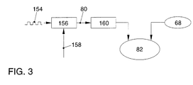
- the test pattern 80 and the sensor signal 68 become one Cross correlation 82 supplied. Before the cross-correlation 82 is carried out, as in FIG. 3 shows that the test pattern 80 is preprocessed.
- a signal 84 results in a Repetition test 86 triggered.
- the number of carried out Measuring cycles compared with a predefinable number. Is the number of performed Measuring cycles smaller than the predetermined number, the signal 88 Repeat test triggered.
- the cross correlation 82 is thus quasi new stimulated. Is the number of measurement cycles carried out equal to the specified one? Number, a diagnosis 92 is carried out via a signal 90.
- diagnosis 92 checks a correlation coefficient of the correlation calculation 82 carried out. has this correlation coefficient has a value close to 1, the test patterns are 80 and the sensor signal 68 is identical in the sense of the correlation calculation.
- Correlation coefficient on the other hand, has a value close to 0, there is none Relationship between the test pattern 80 and the sensor signal 68, so that on an error 94 is detected.
- the number of Retry Checks 86 determine an average correlation factor associated with a Error threshold is compared. If the error threshold is exceeded, this means that the test pattern 80 is in the intake manifold pressure p1, that is to say the sensor signal 68, finds. This means that the function of the intake manifold pressure sensor 34 is flawless. If the error falls below the error threshold, error message 94 is ejected. at A driver can recognize the fault 94, for example, by means of an optical one Signal is given information that the intake manifold pressure sensor 34 is faulty is. Furthermore, the fault 94 can be stored in the engine control unit 56, so that A corresponding note is issued when the next maintenance diagnosis is made.
- a termination 96 of the examination procedure takes place, for example, when the examination of the Release conditions 76 via a signal 98 has shown that the necessary defined release conditions 76 are not given. Furthermore, during the Stimulation of the cross correlation 82 a signal 100 are generated, which is also used for Abort 96 leads.
- the signal 100 may, for example, be an error signal that is at missing or implausible measured variable 68 (sensor signal 68), expiry of an intended Total service life of the intake manifold pressure sensor 34 and / or when the predetermined number of measurement cycles to be carried out during the Repeat check 86 is generated.
- a timer can be started that runs through the exam process Reinitialization 72 starts again. If necessary, it can be provided that the Test procedure expires with each restart of the internal combustion engine 10.
- the cross correlation can be carried out passively or - as explained - actively.
- the passive cross-correlation is the signals to be evaluated, here the Control signal of the exhaust gas recirculation valve 28, the throttle valve 24 or the Tank vent valve 42 and the measurement size 68, processed unaffected.
- the Active cross-correlation described are those that enter the cross-correlation Control signals excited with stimulation signals, so that a sensitivity of the Examination procedure can be increased.
- This stimulation consists in the described overlay with the test pattern 80, which consists of individual pulses exists, the sequence, duration and amplitude of which correspond to the properties of the Internal combustion engine 10 or the intake manifold 20 are adapted.
- the amplitudes of the Test pattern 80 due to the high sensitivity of the cross-correlation calculation 82 be kept as small as possible with a relevant influence on speed and / or torque of the internal combustion engine 10 is not to be expected.
- FIG Release conditions 76 clarifies.
- the release conditions 76 are in one Query 102 linked to blocks of release conditions.
- Figure 3 are schematic two blocks 104 and 106 of release conditions respectively defined Operating conditions of different internal combustion engines 10 shown.
- Block 104 is an internal combustion engine with intake manifold injection and the Block 106 of an internal combustion engine with direct fuel injection assigned.
- Boundary conditions are different release conditions respectively Defined operating parameters during the implementation of the on the basis of Figure 2 explained diagnostic procedure required. Compliance with the release conditions or the achievement of the defined operating parameters is indicated by a Signal 108 to the release condition check 76 acknowledged. Only when this Acknowledgment signal 108 is present, the actual diagnosis of the intake manifold pressure sensor 34 in released as explained.
- additional release conditions are also defined.
- Operating conditions of the internal combustion engine 10 in direct fuel injectors are defined. This is necessary because there are a number of other direct fuel injection systems Actuators are present that can influence intake manifold pressure.
- Actuators are present that can influence intake manifold pressure.
- Direct fuel injection in different operating modes, especially one Shift operation or homogeneous operation, which can also be operated by a clearly different level of the intake manifold pressure, especially by one clearly differing regulation of the intake manifold pressure.
- FIG. 3 illustrates the implementation of the cross correlation 82 in a block diagram between the test pattern 80 and the measurement variable 68.
- the control signal 154 of the Actuator (tank ventilation valve 42, throttle valve 24, exhaust gas recirculation valve 28), a signal module 156 that is to be overlaid with the test pattern fed.
- the signal 154 is superimposed with a pseudorandom signal 158, see above that the test pattern 80 is obtained.
- the test pattern 80 is over a Low pass filter 160 performed, which comprises a PT1 element. This ensures that the Ideally, the signal curve of the test pattern 80 is the signal curve of the measured variable 68 (at the assumption that no faults occur) is identical.
- the slope of the signal 154 is adapted to the slope of the measured variable 68.
- the edges of the measurement variable 68 point first for the so-called delay elements Order typical waveforms of an e-function.
- This e-function is supported by the Low-pass filter 160 modeled for the test pattern 80, so that the subsequent Cross correlation 82 leads to large correlation coefficients (against 1). This will the accuracy of cross correlation increases.
Landscapes
- Engineering & Computer Science (AREA)
- Chemical & Material Sciences (AREA)
- Combustion & Propulsion (AREA)
- Mechanical Engineering (AREA)
- General Engineering & Computer Science (AREA)
- Chemical Kinetics & Catalysis (AREA)
- Electrical Control Of Air Or Fuel Supplied To Internal-Combustion Engine (AREA)
- Combined Controls Of Internal Combustion Engines (AREA)
- Exhaust-Gas Circulating Devices (AREA)
Abstract
Description
- Figur 1
- eine schematische Ansicht einer Verbrennungskraftmaschine;
- Figur 2
- ein Blockschaltbild für die Durchführung eines Verfahrens zum Prüfen eines Messsignales eines Saugrohrdrucksensors;
- Figur 2a
- ein Blockschaltbild für die Festlegung von Freigabebedingungen für das Prüfverfahren und
- Figur 3
- ein Blockschaltbild für die Durchführung der Kreuzkorrelation zwischen einem Testmuster und dem Sensorsignal.
- 110
- Verbrennungskraftmaschine 10 ist im Leerlauf oder es liegt ein Teillastbereich vor, der durch einen Saugrohrdruck und eine Motordrehzahl definiert ist;
- 112
- ein Saugrohrdruck ist stabil, das heißt, eine Differenz zwischen einem maximalen und einem minimalen Saugrohrdruck innerhalb einer Zeitspanne vor der Diagnose und während der Diagnose befindet sich unterhalb eines vorgegebenen Schwellenwertes;
- 114
- wird das Testmuster 80 dem Abgasrückführungsventil 28 überlagert, muss dieses vor Beginn der Diagnose geöffnet sein und die Ventilposition des Abgasrückführungsventils 28 liegt oberhalb eines vorgegebenen Schwellwertes;
- 116
- wird das Testmuster 80 dem Tankentlüftungsventil 42 überlagert, muss dieses vor Beginn der Diagnose geöffnet sein und die Ventilposition des Tankentlüftungsventils 42 muss oberhalb eines vorgegebenen Schwellwertes sein. Wird das Testmuster 80 einer anderen Stellgröße überlagert, ist das Tankentlüftungssystem 36 geschlossen;
- 118
- vom Motorsteuergerät 56 werden keine Fehler an den beteiligten Sensoren und/oder Stellgliedern erkannt;
- 120
- ein Bremsschalter ist für eine festlegbare Zeit vor der Diagnose des Saugrohrdrucksensors 34 nicht geschlossen gewesen, die festlegbare Zeit ist aus einer Fahrzeuggeschwindigkeit ableitbar, da bei einem Bremsvorgang bei höherer Geschwindigkeit der Saugrohrdruck stärker zur Betätigung der Bremsanlage beansprucht wird;
- 122
- eine Betriebstemperatur der Verbrennungskraftmaschine liegt oberhalb eines vorgebbaren Schwellwertes (erfassbar über eine Kühlmitteltemperatur (Kühlwassertemperatur));
- 124
- eine Motordrehzahl ist größer als ein vorgebbarer Schwellwert, insbesondere ist eine Startendedrehzahl erreicht;
- 126
- ein Diagnosemanager gibt die Diagnose des Saugrohrdrucksensors frei;
- 128
- eine elektrische Laständerung im Kraftfahrzeug ist kleiner als ein vorgebbarer Schwellwert;
- 130
- es findet keine Katalysator-Heizmaßnahme, wie beispielsweise eine Beeinflussung des Zündwinkels oder eine Aktivierung der Einspritzung, statt, die Einfluss auf den Saugrohrdruck haben können;
- 131
- es findet keine Nockenwellenverstellung statt;
- 134
- es findet keine Saugrohrumschaltung statt.
- 135
- während der Diagnose wird die Position desjenigen Ventils, dem das Testmuster 80 überlagert wird, beibehalten (bis auf die Änderung durch das Testmuster 80 selber);
- 138
- der nunmehr festen Ventilposition wird das Testmuster 80 überlagert;
- 140
- eine Leerlaufregelung der Verbrennungskraftmaschine 10 wird eingefroren;
- 142
- wenn das Testmuster 80 nicht dem Tankentlüftungsventil 42 überlagert wird, wird dieses vor Beginn der Diagnose geschlossen;
- 144
- wenn das Testmuster 80 nicht dem Abgasrückführungsventil 28 überlagert wird, wird dessen Ventilstellung während der Diagnose eingefroren.
- 146
- es findet keine Betriebsartenumschaltung, beispielsweise zwischen Schichtbetrieb und Homogenbetrieb, statt und es ist eine Mindestzeit seit der letzten Betriebsartenumschaltung vergangen;
- 148
- es findet keine Änderung der Ladungsbewegungsklappe statt.
- 150
- eine Prioritätensteuerung der Betriebsarten (Schichtbetrieb oder Homogenbetrieb) ist so verändert, dass dann, wenn die Diagnose des Saugrohrdrucksensors 34 gestartet wurde, eine Betriebsartenumschaltung nicht stattfindet;
- 152
- eine Saugrohrdruckregelung im Schichtbetrieb wird während der Diagnose des Saugrohrdrucksensors 34 ausgesetzt.
- 10
- Verbrennungskraftmaschine
- 12
- Sauganlage
- 14
- Abgasanlage
- 16
- Abgaskanal
- 18
- Abgasauslass
- 20
- Saugrohr
- 22
- Quelle
- 24
- Drosselklappe
- 26
- Verbindungsleitung
- 28
- Abgasrückführungsventil
- 30
- Lambdasonde
- 32
- Luftmassensensor
- 34
- Saugrohrdrucksensor
- 36
- Tankentlüftungssystem
- 38
- Verbindungsleitung
- 40
- Tank
- 42
- Tankentlüftungsventil
- 44
- Verbindung
- 46
- Filtereinrichtung
- 48
- Aktivkohlebehälter
- 50
- Aktivkohle
- 52
- Sammelraum
- 54
- Verbindung
- 56
- Motorsteuergerät
- 58
- Kraftstoff-Einspritzsystem
- 60
- Einspritzventile
- 62
- Verbindungsleitungen
- 64
- Zylinder
- 66
- Kraftstoffzuführung
- 68
- Sensorsignal (Messgröße)
- 70
- Start des Kraftfahrzeuges
- 72
- Feld (Initialisierung des Prüfungsverfahrens)
- 74
- Abfrage
- 76
- Freigabebedingungen
- 78
- Signal
- 80
- Testmuster
- 82
- Kreuzkorrelation
- 84
- Signal
- 86
- Wiederholungsprüfung
- 88
- Signal
- 90
- Signal
- 92
- Diagnose
- 94
- Fehler
- 96
- Abbruch
- 98
- Signal
- 100
- Signal
- 102
- Abfrage
- 104
- Block
- 106
- Block
- 108
- Signal
- 110
- Freigabebedingungen
- 152
- Freigabebedingungen
- 156
- Signalbaustein
- 158
- Pseudorandomsignal
- 160
- Tiefpassfilter
- p1
- Druck der Verbrennungsluft / Saugrohrdruck
- p2
- Druck des Kraftstoffes
- p3
- Druck des Abgases
- p4
- Druck im Tank
Claims (31)
- Verfahren zum Überprüfen eines Kraftstoff-Einspritzsystems einer Verbrennungskraftmaschine, bei dem Kraftstoff über eine Sauganlage einer Verbrennungsluft zugeführt wird, wobei die Verbrennungsluft unter einem Saugrohrdruck steht, der mittels eines Saugrohrdrucksensors gemessen wird und ein dem aktuellen Saugrohrdruck entsprechendes Sensorsignal einem Motorsteuergerät zur Berücksichtigung bei der Einstellung von Betriebsmodi der Verbrennungskraftmaschine zur Verfügung gestellt wird, dadurch gekennzeichnet, dass das Sensorsignal (68) mit einem Ansteuersignal eines den Saugrohrdruck beeinflussenden Stellmittels (42, 24, 28) kreuzkorreliert wird und ein Korrelationskoeffizient als Diagnosesignal des Saugrohrdrucksensors ausgewertet wird.
- Verfahren nach Anspruch 1, dadurch gekennzeichnet, dass als Ansteuersignal ein Ansteuersignal eines Tankentlüftungsventils (42) verwendet wird.
- Verfahren nach Anspruch 1, dadurch gekennzeichnet, dass als Ansteuersignal ein Ansteuersignal einer Drosselklappe (24) verwendet wird.
- Verfahren nach Anspruch 1, dadurch gekennzeichnet, dass als Ansteuersignal ein Ansteuersignal eines Abgasrückführungsventils (28) ausgewertet wird.
- Verfahren nach einem der vorhergehenden Ansprüche, dadurch gekennzeichnet, dass die Kreuzkorrelation in einer vorgebbaren Anzahl von Messzyklen wiederholt wird.
- Verfahren nach einem der vorhergehenden Ansprüche, dadurch gekennzeichnet, dass die Prüfung des Abgasrückführungssystems in vorgebbaren Zeitintervallen wiederholt wird.
- Verfahren nach einem der vorhergehenden Ansprüche, dadurch gekennzeichnet, dass die Prüfung des Abgasrückführungssystems bei jedem Neustart der Verbrennungskraftmaschine wiederholt wird.
- Verfahren nach einem der vorhergehenden Ansprüche, dadurch gekennzeichnet, dass vor Durchführung der Kreuzkorrelation Freigabebedingungen für das Prüfverfahren überprüft werden.
- Verfahren nach Anspruch 8, dadurch gekennzeichnet, dass die Verbrennungskraftmaschine (10) im Leerlauf ist oder es liegt ein Teillastbereich vor, der durch einen Saugrohrdruck und eine Motordrehzahl definiert ist.
- Verfahren nach einem der vorhergehenden Ansprüche, dadurch gekennzeichnet, dass ein Saugrohrdruck stabil ist, das heißt, eine Differenz zwischen einem maximalen und einem minimalen Saugrohrdruck innerhalb einer Zeitspanne vor der Diagnose und während der Diagnose befindet sich unterhalb eines vorgegebenen Schwellenwertes.
- Verfahren nach einem der vorhergehenden Ansprüche, dadurch gekennzeichnet, dass, wenn das Testmuster (80) dem Abgasrückführungsventil (28) überlagert wird, dieses vor Beginn der Diagnose geöffnet sein muss und die Ventilposition des Abgasrückführungsventils (28) oberhalb eines vorgegebenen Schwellwertes liegt.
- Verfahren nach einem der vorhergehenden Ansprüche, dadurch gekennzeichnet, dass, wenn das Testmuster (80) dem Tankentlüftungsventil (42) überlagert wird, dieses vor Beginn der Diagnose geöffnet sein muss und die Ventilposition des Tankentlüftungsventils (42) oberhalb eines vorgegebenen Schwellwertes sein muss.
- Verfahren nach Anspruch 12, dadurch gekennzeichnet, dass, wenn das Testmuster (80) einer anderen Stellgröße überlagert, das Tankentlüftungssystem (36) geschlossen ist.
- Verfahren nach einem der vorhergehenden Ansprüche, dadurch gekennzeichnet, dass vom Motorsteuergerät (56) keine Fehler an den beteiligten Sensoren und/oder Stellgliedern erkannt werden.
- Verfahren nach einem der vorhergehenden Ansprüche, dadurch gekennzeichnet, dass ein Bremsschalter für eine festlegbare Zeit vor der Diagnose des Saugrohrdrucksensors (34) nicht geschlossen gewesen ist, die festlegbare Zeit aus einer Fahrzeuggeschwindigkeit ableitbar ist, da bei einem Bremsvorgang bei höherer Geschwindigkeit der Saugrohrdruck stärker zur Betätigung der Bremsanlage beansprucht wird.
- Verfahren nach einem der vorhergehenden Ansprüche, dadurch gekennzeichnet, dass eine Betriebstemperatur der Verbrennungskraftmaschine oberhalb eines vorgebbaren Schwellwertes (erfassbar über eine Kühlmitteltemperatur (Kühlwassertemperatur)) liegt.
- Verfahren nach einem der vorhergehenden Ansprüche, dadurch gekennzeichnet, dass eine Motordrehzahl größer als ein vorgebbarer Schwellwert ist, insbesondere eine Startendedrehzahl erreicht ist.
- Verfahren nach einem der vorhergehenden Ansprüche, dadurch gekennzeichnet, dass ein Diagnosemanager die Diagnose des Saugrohrdrucksensors frei gibt.
- Verfahren nach einem der vorhergehenden Ansprüche, dadurch gekennzeichnet, dass eine elektrische Laständerung im Kraftfahrzeug kleiner ist als ein vorgebbarer Schwellwert.
- Verfahren nach einem der vorhergehenden Ansprüche, dadurch gekennzeichnet, dass keine Katalysator-Heizmaßnahme stattfindet, wie beispielsweise eine Beeinflussung des Zündwinkels oder eine Aktivierung der Einspritzung, die Einfluss auf den Saugrohrdruck haben können.
- Verfahren nach einem der vorhergehenden Ansprüche, dadurch gekennzeichnet, dass keine Nockenwellenverstellung stattfindet.
- Verfahren nach einem der vorhergehenden Ansprüche, dadurch gekennzeichnet, dass keine Saugrohrumschaltung stattfindet.
- Verfahren nach einem der vorhergehenden Ansprüche, dadurch gekennzeichnet, dass während der Diagnose die Position desjenigen Ventils, dem das Testmuster (80) überlagert wird, beibehalten wird (bis auf die Änderung durch das Testmuster (80) selber).
- Verfahren nach einem der vorhergehenden Ansprüche, dadurch gekennzeichnet, dass der nunmehr festen Ventilposition das Testmuster (80) überlagert wird.
- Verfahren nach einem der vorhergehenden Ansprüche, dadurch gekennzeichnet, dass eine Leerlaufregelung der Verbrennungskraftmaschine (10) eingefroren wird.
- Verfahren nach einem der vorhergehenden Ansprüche, dadurch gekennzeichnet, dass, wenn das Testmuster (80) nicht dem Tankentlüftungsventil (42) überlagert wird, dieses vor Beginn der Diagnose geschlossen wird.
- Verfahren nach einem der vorhergehenden Ansprüche, dadurch gekennzeichnet, dass, wenn das Testmuster (80) nicht dem Abgasrückführungsventil (28) überlagert wird, dessen Ventilstellung während der Diagnose eingefroren wird.
- Verfahren nach einem der vorhergehenden Ansprüche, dadurch gekennzeichnet, dass keine Betriebsartenumschaltung stattfindet, beispielsweise zwischen Schichtbetrieb und Homogenbetrieb, und es ist eine Mindestzeit seit der letzten Betriebsartenumschaltung vergangen.
- Verfahren nach einem der vorhergehenden Ansprüche, dadurch gekennzeichnet, dass keine Änderung der Ladungsbewegungsklappe stattfindet.
- Verfahren nach einem der vorhergehenden Ansprüche, dadurch gekennzeichnet, dass eine Prioritätensteuerung der Betriebsarten (Schichtbetrieb oder Homogenbetrieb) so verändert ist, dass dann, wenn die Diagnose des Saugrohrdrucksensors (34) gestartet wurde, eine Betriebsartenumschaltung nicht stattfindet.
- Verfahren nach einem der vorhergehenden Ansprüche, dadurch gekennzeichnet, dass eine Saugrohrdruckregelung im Schichtbetrieb während der Diagnose des Saugrohrdrucksensors (34) ausgesetzt wird.
Applications Claiming Priority (2)
| Application Number | Priority Date | Filing Date | Title |
|---|---|---|---|
| DE10038444.7A DE10038444B4 (de) | 2000-08-07 | 2000-08-07 | Verfahren zum Überprüfen eines Kraftstoff-Einspritzsystems |
| DE1038444 | 2000-08-07 |
Publications (3)
| Publication Number | Publication Date |
|---|---|
| EP1179671A2 true EP1179671A2 (de) | 2002-02-13 |
| EP1179671A3 EP1179671A3 (de) | 2005-06-01 |
| EP1179671B1 EP1179671B1 (de) | 2015-09-09 |
Family
ID=7651562
Family Applications (1)
| Application Number | Title | Priority Date | Filing Date |
|---|---|---|---|
| EP01117710.2A Expired - Lifetime EP1179671B1 (de) | 2000-08-07 | 2001-07-27 | Verfahren zum Überprüfen eines Kraftstoff-Einspritzsystems |
Country Status (2)
| Country | Link |
|---|---|
| EP (1) | EP1179671B1 (de) |
| DE (1) | DE10038444B4 (de) |
Cited By (2)
| Publication number | Priority date | Publication date | Assignee | Title |
|---|---|---|---|---|
| US7107108B2 (en) | 2001-06-05 | 2006-09-12 | Florentin Woergoetter | Controller and method of controlling an apparatus using predictive filters |
| WO2018055748A1 (ja) * | 2016-09-26 | 2018-03-29 | 三菱電機株式会社 | 信号処理装置、信号処理方法及び信号処理プログラム |
Families Citing this family (2)
| Publication number | Priority date | Publication date | Assignee | Title |
|---|---|---|---|---|
| DE102008063758B4 (de) * | 2008-12-19 | 2018-02-15 | Volkswagen Ag | Verfahren zum Prüfen eines Tankentlüftungssystems |
| DE102021133885A1 (de) | 2021-12-20 | 2023-06-22 | Bayerische Motoren Werke Aktiengesellschaft | Plausibilisierung einer Funktion eines Sensors in einer Luftzuführung eines Verbrennungsmotors |
Citations (3)
| Publication number | Priority date | Publication date | Assignee | Title |
|---|---|---|---|---|
| DE3226849A1 (de) | 1982-07-17 | 1984-03-22 | Robert Bosch Gmbh, 7000 Stuttgart | Vorrichtung zum ueberwachen eines drucksensors |
| DE19844086A1 (de) | 1998-09-25 | 1999-11-18 | Siemens Ag | Einrichtung zum Steuern einer Brennkraftmaschine |
| EP1013917A2 (de) | 1998-12-23 | 2000-06-28 | Volkswagen Aktiengesellschaft | Verfahren zum Prüfen eines Tankentlüftungssystems |
Family Cites Families (7)
| Publication number | Priority date | Publication date | Assignee | Title |
|---|---|---|---|---|
| DE3112122A1 (de) * | 1981-03-27 | 1982-10-07 | Robert Bosch Gmbh, 7000 Stuttgart | Verfahren und vorrichtung zur fahrzeugdiagnose |
| US5140961A (en) * | 1990-01-12 | 1992-08-25 | Nissan Motor Co., Ltd. | System and method for self diagnosing an engine control system |
| JP3303981B2 (ja) * | 1991-12-20 | 2002-07-22 | 株式会社日立製作所 | エンジン排気ガス浄化装置の診断装置 |
| JP3169298B2 (ja) * | 1993-09-08 | 2001-05-21 | 株式会社日立製作所 | 内燃機関の故障診断装置 |
| GB9426394D0 (en) * | 1994-12-30 | 1995-03-01 | Lucas Ind Plc | Fuel system |
| JP3380366B2 (ja) * | 1995-05-22 | 2003-02-24 | 株式会社日立製作所 | エンジン排気ガス浄化装置の診断装置 |
| US5727533A (en) * | 1996-10-18 | 1998-03-17 | Ford Global Technologies, Inc. | Method and apparatus for monitoring EGR system flow |
-
2000
- 2000-08-07 DE DE10038444.7A patent/DE10038444B4/de not_active Expired - Fee Related
-
2001
- 2001-07-27 EP EP01117710.2A patent/EP1179671B1/de not_active Expired - Lifetime
Patent Citations (3)
| Publication number | Priority date | Publication date | Assignee | Title |
|---|---|---|---|---|
| DE3226849A1 (de) | 1982-07-17 | 1984-03-22 | Robert Bosch Gmbh, 7000 Stuttgart | Vorrichtung zum ueberwachen eines drucksensors |
| DE19844086A1 (de) | 1998-09-25 | 1999-11-18 | Siemens Ag | Einrichtung zum Steuern einer Brennkraftmaschine |
| EP1013917A2 (de) | 1998-12-23 | 2000-06-28 | Volkswagen Aktiengesellschaft | Verfahren zum Prüfen eines Tankentlüftungssystems |
Cited By (8)
| Publication number | Priority date | Publication date | Assignee | Title |
|---|---|---|---|---|
| US7107108B2 (en) | 2001-06-05 | 2006-09-12 | Florentin Woergoetter | Controller and method of controlling an apparatus using predictive filters |
| US7558634B2 (en) | 2001-06-05 | 2009-07-07 | Florentin Woergoetter | Controller and method of controlling an apparatus using predictive filters |
| US8032237B2 (en) | 2001-06-05 | 2011-10-04 | Elverson Hopewell Llc | Correction signal capable of diminishing a future change to an output signal |
| WO2018055748A1 (ja) * | 2016-09-26 | 2018-03-29 | 三菱電機株式会社 | 信号処理装置、信号処理方法及び信号処理プログラム |
| JP6448878B2 (ja) * | 2016-09-26 | 2019-01-09 | 三菱電機株式会社 | 信号処理装置、信号処理方法及び信号処理プログラム |
| CN109716708A (zh) * | 2016-09-26 | 2019-05-03 | 三菱电机株式会社 | 信号处理装置、信号处理方法和信号处理程序 |
| CN109716708B (zh) * | 2016-09-26 | 2021-09-24 | 三菱电机株式会社 | 信号处理装置和信号处理方法 |
| US11132434B2 (en) | 2016-09-26 | 2021-09-28 | Mitsubishi Electric Corporation | Signal processing device, signal processing method and computer readable medium |
Also Published As
| Publication number | Publication date |
|---|---|
| DE10038444A1 (de) | 2002-02-21 |
| EP1179671B1 (de) | 2015-09-09 |
| DE10038444B4 (de) | 2014-07-31 |
| EP1179671A3 (de) | 2005-06-01 |
Similar Documents
| Publication | Publication Date | Title |
|---|---|---|
| EP0795077B1 (de) | Verfahren und vorrichtung zur überwachung eines kraftstoffzumesssystems | |
| DE102005043017B4 (de) | Common-Rail-Kraftstoffeinspritzsystem | |
| DE69410427T2 (de) | Fehlerüberwachungsvorrichtung und -verfahren für ein Sekundärluftzufuhrsystem von Brennkraftmaschinen | |
| DE60025636T2 (de) | Diagnoseverfahren des abgassystems einer brennkraftmaschine | |
| DE102016210579A1 (de) | Verfahren zur diagnose von leckagen nach der entlüftungsdurchfluss-steuerblende | |
| DE10138280A1 (de) | Verfahren und Vorrichtung zur Steuerung des Drucks in einem Kraftstofftank | |
| WO2002012702A1 (de) | Verfahren zur diagnose der funktionstüchtigkeit eines abgasrückführungssystems einer brennkraftmaschine | |
| DE102016219781A1 (de) | Verfahren und Steuergerät zum Abgleich und zur Diagnose eines Abgasrückführmassenstrommessers | |
| DE19515382C2 (de) | Diagnosevorrichtung und -verfahren für ein Verdunstungs-Spülsystem | |
| DE102010041119B4 (de) | Funktionsüberprüfung eines in einem Gaskanal einer Brennkraftmaschine angeordneten Ventils mittels einer Bandpassfilterung | |
| DE19923475A1 (de) | Motorsteuerung mit Abgasrückführung und Verfahren zur Ermittlung des korrekten Funktionierens des AGR-Systems in einem Kraftfahrzeug | |
| DE10037511C1 (de) | Verfahren zur Diagnose der Verstellvorrichtung einer Drallklappe | |
| DE102011081634B4 (de) | Verfahren und Vorrichtung zur Diagnose eines Fehlers in einem Abgasrückführungssystem | |
| EP1179671B1 (de) | Verfahren zum Überprüfen eines Kraftstoff-Einspritzsystems | |
| DE102009033451B4 (de) | Verfahren zum Überprüfen der Funktionsfähigkeit eines Ventils in einem Gaskanal einer Brennkraftmaschine sowie Steuervorrichtung | |
| DE19713180C1 (de) | Verfahren zur Überwachung des Sekundärluftmassenstroms einer Abgasreinigungsanlage | |
| DE102022104858A1 (de) | Verfahren und systeme für ein agr-system | |
| DE10122058A1 (de) | Zweistufige Überwachung eines Dampfrückgewinnungsmanagements | |
| DE3828477C2 (de) | ||
| DE102007057311B3 (de) | Verfahren und Vorrichtung zur Fehlererkennung bei emissionsrelevanten Steuereinrichtungen in einem Fahrzeug | |
| DE10025133B4 (de) | Verfahren zum Überprüfen eines Abgasrückführungssystems | |
| DE10003223B4 (de) | Verfahren zum Prüfen eines Tankentlüftungssystems | |
| DE10118675C1 (de) | Verfahren und Vorrichtung zur Funktionsprüfung eines Bypasselements | |
| DE10036154B4 (de) | Verfahren zum Überprüfen eines Kraftstoffdruckregelsystems | |
| EP1013917B1 (de) | Verfahren zum Prüfen eines Tankentlüftungssystems |
Legal Events
| Date | Code | Title | Description |
|---|---|---|---|
| PUAI | Public reference made under article 153(3) epc to a published international application that has entered the european phase |
Free format text: ORIGINAL CODE: 0009012 |
|
| AK | Designated contracting states |
Kind code of ref document: A2 Designated state(s): AT BE CH CY DE DK ES FI FR GB GR IE IT LI LU MC NL PT SE TR |
|
| AX | Request for extension of the european patent |
Free format text: AL;LT;LV;MK;RO;SI |
|
| PUAL | Search report despatched |
Free format text: ORIGINAL CODE: 0009013 |
|
| AK | Designated contracting states |
Kind code of ref document: A3 Designated state(s): AT BE CH CY DE DK ES FI FR GB GR IE IT LI LU MC NL PT SE TR |
|
| AX | Request for extension of the european patent |
Extension state: AL LT LV MK RO SI |
|
| 17P | Request for examination filed |
Effective date: 20051201 |
|
| AKX | Designation fees paid |
Designated state(s): DE ES FR GB IT |
|
| 17Q | First examination report despatched |
Effective date: 20060123 |
|
| RAP1 | Party data changed (applicant data changed or rights of an application transferred) |
Owner name: VOLKSWAGEN AKTIENGESELLSCHAFT |
|
| GRAP | Despatch of communication of intention to grant a patent |
Free format text: ORIGINAL CODE: EPIDOSNIGR1 |
|
| INTG | Intention to grant announced |
Effective date: 20150317 |
|
| GRAS | Grant fee paid |
Free format text: ORIGINAL CODE: EPIDOSNIGR3 |
|
| GRAA | (expected) grant |
Free format text: ORIGINAL CODE: 0009210 |
|
| AK | Designated contracting states |
Kind code of ref document: B1 Designated state(s): DE ES FR GB IT |
|
| REG | Reference to a national code |
Ref country code: GB Ref legal event code: FG4D Free format text: NOT ENGLISH |
|
| REG | Reference to a national code |
Ref country code: DE Ref legal event code: R096 Ref document number: 50116499 Country of ref document: DE |
|
| PG25 | Lapsed in a contracting state [announced via postgrant information from national office to epo] |
Ref country code: ES Free format text: LAPSE BECAUSE OF FAILURE TO SUBMIT A TRANSLATION OF THE DESCRIPTION OR TO PAY THE FEE WITHIN THE PRESCRIBED TIME-LIMIT Effective date: 20150909 |
|
| PG25 | Lapsed in a contracting state [announced via postgrant information from national office to epo] |
Ref country code: IT Free format text: LAPSE BECAUSE OF FAILURE TO SUBMIT A TRANSLATION OF THE DESCRIPTION OR TO PAY THE FEE WITHIN THE PRESCRIBED TIME-LIMIT Effective date: 20150909 |
|
| REG | Reference to a national code |
Ref country code: DE Ref legal event code: R097 Ref document number: 50116499 Country of ref document: DE |
|
| PLBE | No opposition filed within time limit |
Free format text: ORIGINAL CODE: 0009261 |
|
| STAA | Information on the status of an ep patent application or granted ep patent |
Free format text: STATUS: NO OPPOSITION FILED WITHIN TIME LIMIT |
|
| 26N | No opposition filed |
Effective date: 20160610 |
|
| PGFP | Annual fee paid to national office [announced via postgrant information from national office to epo] |
Ref country code: DE Payment date: 20160731 Year of fee payment: 16 |
|
| GBPC | Gb: european patent ceased through non-payment of renewal fee |
Effective date: 20160727 |
|
| PG25 | Lapsed in a contracting state [announced via postgrant information from national office to epo] |
Ref country code: FR Free format text: LAPSE BECAUSE OF NON-PAYMENT OF DUE FEES Effective date: 20160801 |
|
| REG | Reference to a national code |
Ref country code: FR Ref legal event code: ST Effective date: 20170331 |
|
| PG25 | Lapsed in a contracting state [announced via postgrant information from national office to epo] |
Ref country code: GB Free format text: LAPSE BECAUSE OF NON-PAYMENT OF DUE FEES Effective date: 20160727 |
|
| REG | Reference to a national code |
Ref country code: DE Ref legal event code: R119 Ref document number: 50116499 Country of ref document: DE |
|
| PG25 | Lapsed in a contracting state [announced via postgrant information from national office to epo] |
Ref country code: DE Free format text: LAPSE BECAUSE OF NON-PAYMENT OF DUE FEES Effective date: 20180201 |