EP1179409A2 - Verfahren und Vorrichtung zur Muffenherstellung von Rohren - Google Patents
Verfahren und Vorrichtung zur Muffenherstellung von Rohren Download PDFInfo
- Publication number
- EP1179409A2 EP1179409A2 EP01118317A EP01118317A EP1179409A2 EP 1179409 A2 EP1179409 A2 EP 1179409A2 EP 01118317 A EP01118317 A EP 01118317A EP 01118317 A EP01118317 A EP 01118317A EP 1179409 A2 EP1179409 A2 EP 1179409A2
- Authority
- EP
- European Patent Office
- Prior art keywords
- bush
- shaping
- pipe
- bell
- expanding tool
- Prior art date
- Legal status (The legal status is an assumption and is not a legal conclusion. Google has not performed a legal analysis and makes no representation as to the accuracy of the status listed.)
- Granted
Links
Images

Classifications
-
- B—PERFORMING OPERATIONS; TRANSPORTING
- B29—WORKING OF PLASTICS; WORKING OF SUBSTANCES IN A PLASTIC STATE IN GENERAL
- B29C—SHAPING OR JOINING OF PLASTICS; SHAPING OF MATERIAL IN A PLASTIC STATE, NOT OTHERWISE PROVIDED FOR; AFTER-TREATMENT OF THE SHAPED PRODUCTS, e.g. REPAIRING
- B29C57/00—Shaping of tube ends, e.g. flanging, belling or closing; Apparatus therefor, e.g. collapsible mandrels
- B29C57/02—Belling or enlarging, e.g. combined with forming a groove
- B29C57/04—Belling or enlarging, e.g. combined with forming a groove using mechanical means
- B29C57/06—Belling or enlarging, e.g. combined with forming a groove using mechanical means elastically deformable
Definitions
- This invention refers to a method and an apparatus for bell-shaping the end portion of plastic or layered pipes normally used for piping systems for liquid and gaseous fluids; the invention refers also to a shaping bush of special design, used for the purpose of bell-shaping previously referred to.
- the invention is directed to an apparatus for bell-shaping the end portions of pipes, as mentioned previously, which can be easily transported and used directly at the work site by an operator, to bell-shape the ends of pipes also having different diameters from one another.
- the end portion of the pipe is shaped into the form of a bell by means of special apparatus which require the use of expanding tools comprising a plurality of expanding sectors which can be spread apart in a radial direction to bell-shape an end of a pipe.
- a segmented conformation of the bell-shaped end of a pipe in turn involves seal problems, in that the polygonal outline that the bell assumes, does not offer a satisfactory and homogeneous hydraulic seal over the entire peripheral surface of the bell shaped end of the pipe.
- the main object of the invention is to provide a method for bell-shaping the ends of pipes, which is easy to perform and which offers the possibility of maintaining the peripheral outline of a bell-shaped end of a pipe, perfectly circular in order to ensure optimal watertight or sealing conditions.
- a further object of the invention is to provide a method for bell-shaping the ends of pipes, as mentioned above, which may be easily adaptable for bell-shaping ends of pipes of any diameter.
- a still further object of the invention is to provide an apparatus for bell-shaping the ends of pipes by means of the aforementioned method, which is structurally simple, of minimum overall dimensions and extremely lightweight, and by which it is possible to bell-shape the ends of pipes of different diameters by quick and easy replacement of a few auxiliary shaping parts.
- a still further object of this invention is to provide an apparatus of the aforementioned type, suitable either for bench-top use, or for manual use.
- a further object of the invention is to provide an auxiliary shaping bush of simple design and suitable for bell shaping an end portion of a pipe by the method and the apparatus referred to above.
- the objects of the invention can be achieved by means of a method for bell-shaping the end portions of pipes according to claim 1, by means of an apparatus according to claim 2, and by means of a shaping bush according to claim 8.
- the basic feature of this invention lies in the use of a special shaping bush of deformable plastic material, and a special expanding tool, which are inserted into an end of a pipe, by a length substantially equal to that of the bell end to be performed, which is thus shaped by progressively expanding the shaping bush in a radial direction against the inner surface of the pipe end, by forcing and drawing the expanding tool to axially slide along the bush.
- a method for bell-shaping an end portion of a pipe of plastic material or layered material characterised by the steps of:
- an apparatus for bell-shaping end portions of pipes, the apparatus comprising:
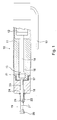
- the apparatus according to the invention for bell-shaping the end portions of pipes of plastic or layered material, substantially comprises a linear actuator 10, a shaping bush 22 made of deformable plastic material, for example polythene, and an expanding tool 19 operatively and disengageably connected to the actuator, which is forced to slide inside the bush 22, after the same bush 22 and the tool 19 have been inserted into and end portion of a pipe 37 to bell shaped by a progressive radial expansion of the bush against the end portion of the pipe.
- a linear actuator 10 substantially comprises a linear actuator 10, a shaping bush 22 made of deformable plastic material, for example polythene, and an expanding tool 19 operatively and disengageably connected to the actuator, which is forced to slide inside the bush 22, after the same bush 22 and the tool 19 have been inserted into and end portion of a pipe 37 to bell shaped by a progressive radial expansion of the bush against the end portion of the pipe.
- the linear actuator 10 may be of any suitable type; for example may be of pneumatic or hydraulic type, comprising a handgrip 11 which houses a double-acting cylinder 12 and an oil pumping unit which can be operated for example by means of a control lever 13.
- the double-acting cylinder 12 of the actuator comprises a rod 14 having a shaped head 15, axially sliding along a guide hole 16 which extends substantially along the entire length of the handgrip 11; the handgripping 12 is provided with a threaded end 17 onto which is screwed a guide member 18 for an expanding tool 19.
- the tool 19, as shown, comprises a shaped head 20 having a cylindrical portion and a conical portion at the forward end of a stem 21, and is of such shape as to gradually and evenly expand the bush 22 of deformable plastic material, and consequently to bell-shape the end portion of a pipe, as explained further on.
- the stem 21 of the expanding tool 19 comprises a first stem portion of reduced diameter, to freely slide inside the hole of the shaping bush, and an intermediate cylindrical portion 21', between the stem portion 21 and the head 20, having a diameter larger than the diameter of the first stem portion 21, and the inside diameter of diameters of the hole of the shaping bush 22.
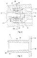
- the stem portion 21 of the expanding tool 19 freely passes through an axial hole 23 in the guide member 18, to engage and disengage with an automatic clamping device at the head 15 of the rod 14 of the cylinder 12.
- the hole 23 in the guide member 18, at the fore end, opens into a widened cavity 24 suitable for housing the shaped head 20 of the expanding tool 19.
- the stem 21 of the expanding tool at its rear end is provided with an annular groove 21A, and extends with a shank 21B of reduced diameter, to penetrate into a ball type collet comprising an external bushing 25, axially sliding with respect to an internal bushing 26 screwed onto the head 15 of the rod 14 of the control cylinder.
- the internal bushing 26, in an intermediate position, comprises a set of circumferentially arranged radial holes for a plurality of clamping balls 27, designed to engage with the annular groove 21A at the rear end of the stem 21 of the expanding tool.
- the external bushing 25 in turn presents a conical inner surface 25A which converges in the direction of the head 15, and is biased forward by a spring 28.
- the balls 27 of the collet are normally maintained in a disengaged condition of the stem 21, by means of a cup-shaped stop member 29, having a guide shank 30 axially sliding with respect to the internal bushing 26 and to the head 15, of the cylinder rod 14, against the action of a biasing spring 31.
- the bush 22 comprises a tubular body 22A of plastic material which extends axially for a length substantially corresponding to the length of the bell 37A to be formed at an end portion of a pipe; the bush body 22 comprises a cylindrical outer surface 32 which ends in a rear flange 33 providing a resting portion for maintaining the bush 22 against a shoulder surface at the fore end of the actuator, as well as a shoulder for resting the end of a pipe 36.
- the bush 22, in the example of figure 3, in turn presents bore having a conical inner surface 34, which converges in the direction of the rear end of the bush, from a widely flared bore 35 at the fore end of the bush 22 opposite the flange 33.
- the inner surface 34 of the bush 22 in turn opens towards widened cylindrical cavity 36 in correspondence with the flange 33.
- the axial lengths and angular tapering of the conical surfaces 34 and 35 should be appropriately calculated and correlated to the shape of the bell-shaped end portion of the pipe, to be formed; more precisely, the flared portion 35 serves to initially shape a conical portion of the bush and the end portion of the pipe, while the length and tapering of the inner conical surface 34 are correlated to the length and shape of the remaining bell portion to be formed. More precisely, whenever it is necessary to shape a conical bell, the internal surface 34 of the bush 22 must have an identical tapering ratio to that of the bell to be formed, but in dual form, that is to say with a tapering opposite to that of the bell wall.
- Figure 3 shows a bush 22 having a conical inner surface to gradually expand the bell to be formed at the end of a pipe, as explained further on; however, the bush 22 could present an internal surface with a different longitudinal shape from the one shown, for example, cylindrical, to likewise form the bell.
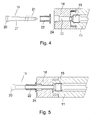
- the method for bell-shaping an end portion of a pipe comprises the steps of providing a bush 22 of deformable plastic material, as described previously, that is having a cylindrical outer surface which conforms to the internal cylindrical surface of an end portion of a pipe, and an inner surface having a longitudinal profile parallel to or converging in opposite direction in respect to the outer surface of the same bush or the longitudinal inner profile of the bell to be formed; providing a tool 19 having a head 20 shaped for radially expanding the bush 22, and disposing the shaping bush on the tool, or threading the latter into the bush 22 before operatively connecting the expanding tool to an actuator.
- the expanding tool 19 with the bush 22 is then threaded into one end portion of a pipe 37 to be bell-shaped, as shown in figure 6, with the flange 33 of the bush 22 resting against the front surface of the guiding member 18 for the tool.
- the end portion 37A of the pipe 37 is shaped into the form of a bell by causing a progressive expansion of the bush 22 against the inner surface of the cylindrical wall of the pipe 37, by forcibly sliding the head 20 of the expanding tool along the inner surface of the bush 22 exerting a drawing action by means of the actuator 10, while the bush 22 and the end portion of the pipe 37 are held against the front stop surface of the guide member 18.
- Figures 4 to 7 show the basic steps of the method for bell-shaping the end portion of a pipe, illustrated previously.
Landscapes
- Engineering & Computer Science (AREA)
- Mechanical Engineering (AREA)
- Shaping Of Tube Ends By Bending Or Straightening (AREA)
- Re-Forming, After-Treatment, Cutting And Transporting Of Glass Products (AREA)
- Blow-Moulding Or Thermoforming Of Plastics Or The Like (AREA)
- Making Paper Articles (AREA)
- Manufacture, Treatment Of Glass Fibers (AREA)
- Forging (AREA)
Applications Claiming Priority (2)
| Application Number | Priority Date | Filing Date | Title |
|---|---|---|---|
| IT2000MI001798A IT1318312B1 (it) | 2000-08-02 | 2000-08-02 | Metodo ed apparecchiatura per conformare a bicchiere le estremita' ditubi |
| ITMI001798 | 2000-08-02 |
Publications (3)
| Publication Number | Publication Date |
|---|---|
| EP1179409A2 true EP1179409A2 (de) | 2002-02-13 |
| EP1179409A3 EP1179409A3 (de) | 2002-05-29 |
| EP1179409B1 EP1179409B1 (de) | 2004-08-11 |
Family
ID=11445646
Family Applications (1)
| Application Number | Title | Priority Date | Filing Date |
|---|---|---|---|
| EP01118317A Expired - Lifetime EP1179409B1 (de) | 2000-08-02 | 2001-07-27 | Verfahren und Vorrichtung zur Muffenherstellung von Rohren |
Country Status (6)
| Country | Link |
|---|---|
| EP (1) | EP1179409B1 (de) |
| AT (1) | ATE273116T1 (de) |
| DE (1) | DE60104781T2 (de) |
| ES (1) | ES2223691T3 (de) |
| IT (1) | IT1318312B1 (de) |
| PT (1) | PT1179409E (de) |
Cited By (2)
| Publication number | Priority date | Publication date | Assignee | Title |
|---|---|---|---|---|
| CN102672955A (zh) * | 2012-05-22 | 2012-09-19 | 吴江市三达五金工具厂 | 一种可更换加热头的塑料管头部处理机 |
| WO2019116170A1 (en) * | 2017-12-12 | 2019-06-20 | Aquatechnik Group S.P.A. | A device for expanding and shaping the end of pipes and an extracting member for use with such a device |
Citations (2)
| Publication number | Priority date | Publication date | Assignee | Title |
|---|---|---|---|---|
| DE29618268U1 (de) * | 1996-10-22 | 1996-12-05 | Novopress Gmbh | Aufweiteinrichtung zum Aufweiten von Rohrenden |
| JPH09183157A (ja) * | 1995-12-28 | 1997-07-15 | Takanori Yamanami | 合成樹脂製管の拡管方法及び接続方法 |
-
2000
- 2000-08-02 IT IT2000MI001798A patent/IT1318312B1/it active
-
2001
- 2001-07-27 PT PT01118317T patent/PT1179409E/pt unknown
- 2001-07-27 ES ES01118317T patent/ES2223691T3/es not_active Expired - Lifetime
- 2001-07-27 AT AT01118317T patent/ATE273116T1/de not_active IP Right Cessation
- 2001-07-27 EP EP01118317A patent/EP1179409B1/de not_active Expired - Lifetime
- 2001-07-27 DE DE60104781T patent/DE60104781T2/de not_active Expired - Lifetime
Patent Citations (2)
| Publication number | Priority date | Publication date | Assignee | Title |
|---|---|---|---|---|
| JPH09183157A (ja) * | 1995-12-28 | 1997-07-15 | Takanori Yamanami | 合成樹脂製管の拡管方法及び接続方法 |
| DE29618268U1 (de) * | 1996-10-22 | 1996-12-05 | Novopress Gmbh | Aufweiteinrichtung zum Aufweiten von Rohrenden |
Non-Patent Citations (1)
| Title |
|---|
| PATENT ABSTRACTS OF JAPAN vol. 1997, no. 11, 28 November 1997 (1997-11-28) -& JP 09 183157 A (YAMANAMI TAKANORI), 15 July 1997 (1997-07-15) * |
Cited By (5)
| Publication number | Priority date | Publication date | Assignee | Title |
|---|---|---|---|---|
| CN102672955A (zh) * | 2012-05-22 | 2012-09-19 | 吴江市三达五金工具厂 | 一种可更换加热头的塑料管头部处理机 |
| CN102672955B (zh) * | 2012-05-22 | 2014-02-26 | 吴江市三达五金工具厂 | 一种可更换加热头的塑料管头部处理机 |
| WO2019116170A1 (en) * | 2017-12-12 | 2019-06-20 | Aquatechnik Group S.P.A. | A device for expanding and shaping the end of pipes and an extracting member for use with such a device |
| JP2021505409A (ja) * | 2017-12-12 | 2021-02-18 | アクアテクニック・グループ・ソシエタ・ペル・アツィオーニ | パイプの端部を拡大および成形するためのデバイス、ならびにこのデバイスと共に使用するための引き抜き部材 |
| US11660804B2 (en) | 2017-12-12 | 2023-05-30 | Aquatechnik Group S.P.A. | Device for expanding and shaping the end of pipes and an extracting member for use with such a device |
Also Published As
| Publication number | Publication date |
|---|---|
| ATE273116T1 (de) | 2004-08-15 |
| DE60104781D1 (de) | 2004-09-16 |
| EP1179409B1 (de) | 2004-08-11 |
| DE60104781T2 (de) | 2005-08-25 |
| ITMI20001798A0 (it) | 2000-08-02 |
| ITMI20001798A1 (it) | 2002-02-02 |
| IT1318312B1 (it) | 2003-07-28 |
| ES2223691T3 (es) | 2005-03-01 |
| EP1179409A3 (de) | 2002-05-29 |
| PT1179409E (pt) | 2005-01-31 |
Similar Documents
| Publication | Publication Date | Title |
|---|---|---|
| US5558375A (en) | Quick attach, reusable hose fittings | |
| JP4992098B2 (ja) | ノンボルト継手構造およびノンボルト継手構造を形成する方法 | |
| US7469936B2 (en) | Pipe coupling | |
| JP2931836B2 (ja) | 管用気密継手の製作方法 | |
| US7350831B2 (en) | End structure of water pipe | |
| US20080001404A1 (en) | Coupling | |
| US2547889A (en) | Pipe connector | |
| US9897238B2 (en) | Tube coupling device | |
| US20100327579A1 (en) | Fluid fitting | |
| CZ287561B6 (cs) | Způsob upevňování hadice na vsuvce, vysokotlaký spoj hadice jím vytvořený, a způsob výroby vsuvky pro tento spoj | |
| US6508097B2 (en) | Modular system for expanding and reducing tubing | |
| US3338598A (en) | Coupling method and devices for lined pipe | |
| US3211476A (en) | Coupling for a fluid conduit | |
| EP1211454A2 (de) | Rohrendearmaturen | |
| US4223919A (en) | Device for coupling hose, pipe or the like | |
| US5150925A (en) | Hose fitting | |
| US7178838B2 (en) | Nut and tail assembly | |
| US4934745A (en) | Flexible hose coupling | |
| US5904063A (en) | Tube beading apparatus | |
| US8057215B2 (en) | Device for preparing pipe ends for jointing | |
| EP1179409B1 (de) | Verfahren und Vorrichtung zur Muffenherstellung von Rohren | |
| US20040061333A1 (en) | Conduit coupling | |
| JP5584583B2 (ja) | 樹脂管用継手及び樹脂管用継手を用いた連結方法 | |
| JP7347882B1 (ja) | 管継手とパイプの接続方法及び接続構造体 | |
| CN113374963B (zh) | 一种管连接装置 |
Legal Events
| Date | Code | Title | Description |
|---|---|---|---|
| PUAI | Public reference made under article 153(3) epc to a published international application that has entered the european phase |
Free format text: ORIGINAL CODE: 0009012 |
|
| AK | Designated contracting states |
Kind code of ref document: A2 Designated state(s): AT BE CH CY DE DK ES FI FR GB GR IE IT LI LU MC NL PT SE TR |
|
| AX | Request for extension of the european patent |
Free format text: AL;LT;LV;MK;RO;SI |
|
| PUAL | Search report despatched |
Free format text: ORIGINAL CODE: 0009013 |
|
| AK | Designated contracting states |
Kind code of ref document: A3 Designated state(s): AT BE CH CY DE DK ES FI FR GB GR IE IT LI LU MC NL PT SE TR |
|
| AX | Request for extension of the european patent |
Free format text: AL;LT;LV;MK;RO;SI |
|
| 17P | Request for examination filed |
Effective date: 20020826 |
|
| AKX | Designation fees paid |
Designated state(s): AT BE CH CY DE DK ES FI FR GB GR IE IT LI LU MC NL PT SE TR |
|
| 17Q | First examination report despatched |
Effective date: 20030519 |
|
| GRAP | Despatch of communication of intention to grant a patent |
Free format text: ORIGINAL CODE: EPIDOSNIGR1 |
|
| GRAS | Grant fee paid |
Free format text: ORIGINAL CODE: EPIDOSNIGR3 |
|
| GRAA | (expected) grant |
Free format text: ORIGINAL CODE: 0009210 |
|
| AK | Designated contracting states |
Kind code of ref document: B1 Designated state(s): AT BE CH CY DE DK ES FI FR GB GR IE IT LI LU MC NL PT SE TR |
|
| PG25 | Lapsed in a contracting state [announced via postgrant information from national office to epo] |
Ref country code: CH Free format text: LAPSE BECAUSE OF FAILURE TO SUBMIT A TRANSLATION OF THE DESCRIPTION OR TO PAY THE FEE WITHIN THE PRESCRIBED TIME-LIMIT Effective date: 20040811 Ref country code: BE Free format text: LAPSE BECAUSE OF FAILURE TO SUBMIT A TRANSLATION OF THE DESCRIPTION OR TO PAY THE FEE WITHIN THE PRESCRIBED TIME-LIMIT Effective date: 20040811 Ref country code: AT Free format text: LAPSE BECAUSE OF FAILURE TO SUBMIT A TRANSLATION OF THE DESCRIPTION OR TO PAY THE FEE WITHIN THE PRESCRIBED TIME-LIMIT Effective date: 20040811 Ref country code: LI Free format text: LAPSE BECAUSE OF FAILURE TO SUBMIT A TRANSLATION OF THE DESCRIPTION OR TO PAY THE FEE WITHIN THE PRESCRIBED TIME-LIMIT Effective date: 20040811 Ref country code: FI Free format text: LAPSE BECAUSE OF FAILURE TO SUBMIT A TRANSLATION OF THE DESCRIPTION OR TO PAY THE FEE WITHIN THE PRESCRIBED TIME-LIMIT Effective date: 20040811 Ref country code: NL Free format text: LAPSE BECAUSE OF FAILURE TO SUBMIT A TRANSLATION OF THE DESCRIPTION OR TO PAY THE FEE WITHIN THE PRESCRIBED TIME-LIMIT Effective date: 20040811 Ref country code: TR Free format text: LAPSE BECAUSE OF FAILURE TO SUBMIT A TRANSLATION OF THE DESCRIPTION OR TO PAY THE FEE WITHIN THE PRESCRIBED TIME-LIMIT Effective date: 20040811 |
|
| REG | Reference to a national code |
Ref country code: GB Ref legal event code: FG4D |
|
| REG | Reference to a national code |
Ref country code: CH Ref legal event code: EP |
|
| REG | Reference to a national code |
Ref country code: IE Ref legal event code: FG4D |
|
| REF | Corresponds to: |
Ref document number: 60104781 Country of ref document: DE Date of ref document: 20040916 Kind code of ref document: P |
|
| PG25 | Lapsed in a contracting state [announced via postgrant information from national office to epo] |
Ref country code: SE Free format text: LAPSE BECAUSE OF FAILURE TO SUBMIT A TRANSLATION OF THE DESCRIPTION OR TO PAY THE FEE WITHIN THE PRESCRIBED TIME-LIMIT Effective date: 20041111 Ref country code: DK Free format text: LAPSE BECAUSE OF FAILURE TO SUBMIT A TRANSLATION OF THE DESCRIPTION OR TO PAY THE FEE WITHIN THE PRESCRIBED TIME-LIMIT Effective date: 20041111 |
|
| REG | Reference to a national code |
Ref country code: GR Ref legal event code: EP Ref document number: 20040403469 Country of ref document: GR |
|
| REG | Reference to a national code |
Ref country code: PT Ref legal event code: SC4A Effective date: 20041111 |
|
| NLV1 | Nl: lapsed or annulled due to failure to fulfill the requirements of art. 29p and 29m of the patents act | ||
| REG | Reference to a national code |
Ref country code: CH Ref legal event code: PL |
|
| REG | Reference to a national code |
Ref country code: ES Ref legal event code: FG2A Ref document number: 2223691 Country of ref document: ES Kind code of ref document: T3 |
|
| PLBE | No opposition filed within time limit |
Free format text: ORIGINAL CODE: 0009261 |
|
| STAA | Information on the status of an ep patent application or granted ep patent |
Free format text: STATUS: NO OPPOSITION FILED WITHIN TIME LIMIT |
|
| ET | Fr: translation filed | ||
| PG25 | Lapsed in a contracting state [announced via postgrant information from national office to epo] |
Ref country code: GB Free format text: LAPSE BECAUSE OF NON-PAYMENT OF DUE FEES Effective date: 20050727 Ref country code: LU Free format text: LAPSE BECAUSE OF NON-PAYMENT OF DUE FEES Effective date: 20050727 Ref country code: IE Free format text: LAPSE BECAUSE OF NON-PAYMENT OF DUE FEES Effective date: 20050727 Ref country code: CY Free format text: LAPSE BECAUSE OF FAILURE TO SUBMIT A TRANSLATION OF THE DESCRIPTION OR TO PAY THE FEE WITHIN THE PRESCRIBED TIME-LIMIT Effective date: 20050727 |
|
| PG25 | Lapsed in a contracting state [announced via postgrant information from national office to epo] |
Ref country code: MC Free format text: LAPSE BECAUSE OF NON-PAYMENT OF DUE FEES Effective date: 20050731 |
|
| 26N | No opposition filed |
Effective date: 20050512 |
|
| GBPC | Gb: european patent ceased through non-payment of renewal fee |
Effective date: 20050727 |
|
| REG | Reference to a national code |
Ref country code: IE Ref legal event code: MM4A |
|
| REG | Reference to a national code |
Ref country code: FR Ref legal event code: TP |
|
| REG | Reference to a national code |
Ref country code: ES Ref legal event code: PC2A |
|
| REG | Reference to a national code |
Ref country code: FR Ref legal event code: PLFP Year of fee payment: 16 |
|
| REG | Reference to a national code |
Ref country code: FR Ref legal event code: PLFP Year of fee payment: 17 |
|
| REG | Reference to a national code |
Ref country code: DE Ref legal event code: R082 Ref document number: 60104781 Country of ref document: DE Representative=s name: MAIWALD PATENTANWALTS- UND RECHTSANWALTSGESELL, DE |
|
| REG | Reference to a national code |
Ref country code: FR Ref legal event code: PLFP Year of fee payment: 18 |
|
| PGFP | Annual fee paid to national office [announced via postgrant information from national office to epo] |
Ref country code: FR Payment date: 20200728 Year of fee payment: 20 Ref country code: GR Payment date: 20200729 Year of fee payment: 20 Ref country code: DE Payment date: 20200729 Year of fee payment: 20 Ref country code: PT Payment date: 20200702 Year of fee payment: 20 Ref country code: ES Payment date: 20200803 Year of fee payment: 20 |
|
| PGFP | Annual fee paid to national office [announced via postgrant information from national office to epo] |
Ref country code: IT Payment date: 20200722 Year of fee payment: 20 |
|
| REG | Reference to a national code |
Ref country code: DE Ref legal event code: R071 Ref document number: 60104781 Country of ref document: DE |
|
| PG25 | Lapsed in a contracting state [announced via postgrant information from national office to epo] |
Ref country code: PT Free format text: LAPSE BECAUSE OF EXPIRATION OF PROTECTION Effective date: 20210804 |
|
| PG25 | Lapsed in a contracting state [announced via postgrant information from national office to epo] |
Ref country code: ES Free format text: LAPSE BECAUSE OF EXPIRATION OF PROTECTION Effective date: 20210728 |