EP1179384B1 - Process and machine for uniting rotatable machine components - Google Patents
Process and machine for uniting rotatable machine components Download PDFInfo
- Publication number
- EP1179384B1 EP1179384B1 EP01126764A EP01126764A EP1179384B1 EP 1179384 B1 EP1179384 B1 EP 1179384B1 EP 01126764 A EP01126764 A EP 01126764A EP 01126764 A EP01126764 A EP 01126764A EP 1179384 B1 EP1179384 B1 EP 1179384B1
- Authority
- EP
- European Patent Office
- Prior art keywords
- spindle
- forming tool
- end portion
- component
- tool
- Prior art date
- Legal status (The legal status is an assumption and is not a legal conclusion. Google has not performed a legal analysis and makes no representation as to the accuracy of the status listed.)
- Expired - Lifetime
Links
Images


Classifications
-
- B—PERFORMING OPERATIONS; TRANSPORTING
- B23—MACHINE TOOLS; METAL-WORKING NOT OTHERWISE PROVIDED FOR
- B23P—METAL-WORKING NOT OTHERWISE PROVIDED FOR; COMBINED OPERATIONS; UNIVERSAL MACHINE TOOLS
- B23P11/00—Connecting or disconnecting metal parts or objects by metal-working techniques not otherwise provided for
- B23P11/005—Connecting or disconnecting metal parts or objects by metal-working techniques not otherwise provided for by expanding or crimping
-
- B—PERFORMING OPERATIONS; TRANSPORTING
- B23—MACHINE TOOLS; METAL-WORKING NOT OTHERWISE PROVIDED FOR
- B23P—METAL-WORKING NOT OTHERWISE PROVIDED FOR; COMBINED OPERATIONS; UNIVERSAL MACHINE TOOLS
- B23P11/00—Connecting or disconnecting metal parts or objects by metal-working techniques not otherwise provided for
-
- B—PERFORMING OPERATIONS; TRANSPORTING
- B60—VEHICLES IN GENERAL
- B60B—VEHICLE WHEELS; CASTORS; AXLES FOR WHEELS OR CASTORS; INCREASING WHEEL ADHESION
- B60B27/00—Hubs
- B60B27/001—Hubs with roller-bearings
-
- B—PERFORMING OPERATIONS; TRANSPORTING
- B60—VEHICLES IN GENERAL
- B60B—VEHICLE WHEELS; CASTORS; AXLES FOR WHEELS OR CASTORS; INCREASING WHEEL ADHESION
- B60B35/00—Axle units; Parts thereof ; Arrangements for lubrication of axles
- B60B35/12—Torque-transmitting axles
- B60B35/18—Arrangement of bearings
-
- F—MECHANICAL ENGINEERING; LIGHTING; HEATING; WEAPONS; BLASTING
- F16—ENGINEERING ELEMENTS AND UNITS; GENERAL MEASURES FOR PRODUCING AND MAINTAINING EFFECTIVE FUNCTIONING OF MACHINES OR INSTALLATIONS; THERMAL INSULATION IN GENERAL
- F16C—SHAFTS; FLEXIBLE SHAFTS; ELEMENTS OR CRANKSHAFT MECHANISMS; ROTARY BODIES OTHER THAN GEARING ELEMENTS; BEARINGS
- F16C19/00—Bearings with rolling contact, for exclusively rotary movement
- F16C19/22—Bearings with rolling contact, for exclusively rotary movement with bearing rollers essentially of the same size in one or more circular rows, e.g. needle bearings
- F16C19/34—Bearings with rolling contact, for exclusively rotary movement with bearing rollers essentially of the same size in one or more circular rows, e.g. needle bearings for both radial and axial load
- F16C19/38—Bearings with rolling contact, for exclusively rotary movement with bearing rollers essentially of the same size in one or more circular rows, e.g. needle bearings for both radial and axial load with two or more rows of rollers
- F16C19/383—Bearings with rolling contact, for exclusively rotary movement with bearing rollers essentially of the same size in one or more circular rows, e.g. needle bearings for both radial and axial load with two or more rows of rollers with tapered rollers, i.e. rollers having essentially the shape of a truncated cone
- F16C19/385—Bearings with rolling contact, for exclusively rotary movement with bearing rollers essentially of the same size in one or more circular rows, e.g. needle bearings for both radial and axial load with two or more rows of rollers with tapered rollers, i.e. rollers having essentially the shape of a truncated cone with two rows, i.e. double-row tapered roller bearings
- F16C19/386—Bearings with rolling contact, for exclusively rotary movement with bearing rollers essentially of the same size in one or more circular rows, e.g. needle bearings for both radial and axial load with two or more rows of rollers with tapered rollers, i.e. rollers having essentially the shape of a truncated cone with two rows, i.e. double-row tapered roller bearings in O-arrangement
-
- F—MECHANICAL ENGINEERING; LIGHTING; HEATING; WEAPONS; BLASTING
- F16—ENGINEERING ELEMENTS AND UNITS; GENERAL MEASURES FOR PRODUCING AND MAINTAINING EFFECTIVE FUNCTIONING OF MACHINES OR INSTALLATIONS; THERMAL INSULATION IN GENERAL
- F16C—SHAFTS; FLEXIBLE SHAFTS; ELEMENTS OR CRANKSHAFT MECHANISMS; ROTARY BODIES OTHER THAN GEARING ELEMENTS; BEARINGS
- F16C35/00—Rigid support of bearing units; Housings, e.g. caps, covers
- F16C35/04—Rigid support of bearing units; Housings, e.g. caps, covers in the case of ball or roller bearings
- F16C35/06—Mounting or dismounting of ball or roller bearings; Fixing them onto shaft or in housing
- F16C35/063—Fixing them on the shaft
-
- G—PHYSICS
- G01—MEASURING; TESTING
- G01P—MEASURING LINEAR OR ANGULAR SPEED, ACCELERATION, DECELERATION, OR SHOCK; INDICATING PRESENCE, ABSENCE, OR DIRECTION, OF MOVEMENT
- G01P3/00—Measuring linear or angular speed; Measuring differences of linear or angular speeds
- G01P3/42—Devices characterised by the use of electric or magnetic means
- G01P3/44—Devices characterised by the use of electric or magnetic means for measuring angular speed
- G01P3/443—Devices characterised by the use of electric or magnetic means for measuring angular speed mounted in bearings
- G01P3/446—Devices characterised by the use of electric or magnetic means for measuring angular speed mounted in bearings mounted between two axially spaced rows of rolling elements
-
- B—PERFORMING OPERATIONS; TRANSPORTING
- B60—VEHICLES IN GENERAL
- B60B—VEHICLE WHEELS; CASTORS; AXLES FOR WHEELS OR CASTORS; INCREASING WHEEL ADHESION
- B60B2310/00—Manufacturing methods
- B60B2310/20—Shaping
- B60B2310/208—Shaping by forging
-
- B—PERFORMING OPERATIONS; TRANSPORTING
- B60—VEHICLES IN GENERAL
- B60B—VEHICLE WHEELS; CASTORS; AXLES FOR WHEELS OR CASTORS; INCREASING WHEEL ADHESION
- B60B2310/00—Manufacturing methods
- B60B2310/20—Shaping
- B60B2310/228—Shaping by machining
-
- B—PERFORMING OPERATIONS; TRANSPORTING
- B60—VEHICLES IN GENERAL
- B60B—VEHICLE WHEELS; CASTORS; AXLES FOR WHEELS OR CASTORS; INCREASING WHEEL ADHESION
- B60B2310/00—Manufacturing methods
- B60B2310/30—Manufacturing methods joining
- B60B2310/306—Manufacturing methods joining by clamping or wedging, e.g. by clamping inserts as joining means
-
- B—PERFORMING OPERATIONS; TRANSPORTING
- B60—VEHICLES IN GENERAL
- B60B—VEHICLE WHEELS; CASTORS; AXLES FOR WHEELS OR CASTORS; INCREASING WHEEL ADHESION
- B60B2310/00—Manufacturing methods
- B60B2310/30—Manufacturing methods joining
- B60B2310/316—Manufacturing methods joining by press-fitting, shrink-fitting
-
- B—PERFORMING OPERATIONS; TRANSPORTING
- B60—VEHICLES IN GENERAL
- B60B—VEHICLE WHEELS; CASTORS; AXLES FOR WHEELS OR CASTORS; INCREASING WHEEL ADHESION
- B60B2360/00—Materials; Physical forms thereof
- B60B2360/10—Metallic materials
-
- B—PERFORMING OPERATIONS; TRANSPORTING
- B60—VEHICLES IN GENERAL
- B60B—VEHICLE WHEELS; CASTORS; AXLES FOR WHEELS OR CASTORS; INCREASING WHEEL ADHESION
- B60B2360/00—Materials; Physical forms thereof
- B60B2360/10—Metallic materials
- B60B2360/102—Steel
-
- B—PERFORMING OPERATIONS; TRANSPORTING
- B60—VEHICLES IN GENERAL
- B60B—VEHICLE WHEELS; CASTORS; AXLES FOR WHEELS OR CASTORS; INCREASING WHEEL ADHESION
- B60B2380/00—Bearings
- B60B2380/10—Type
- B60B2380/14—Roller bearings
-
- F—MECHANICAL ENGINEERING; LIGHTING; HEATING; WEAPONS; BLASTING
- F16—ENGINEERING ELEMENTS AND UNITS; GENERAL MEASURES FOR PRODUCING AND MAINTAINING EFFECTIVE FUNCTIONING OF MACHINES OR INSTALLATIONS; THERMAL INSULATION IN GENERAL
- F16C—SHAFTS; FLEXIBLE SHAFTS; ELEMENTS OR CRANKSHAFT MECHANISMS; ROTARY BODIES OTHER THAN GEARING ELEMENTS; BEARINGS
- F16C2326/00—Articles relating to transporting
- F16C2326/01—Parts of vehicles in general
- F16C2326/02—Wheel hubs or castors
-
- F—MECHANICAL ENGINEERING; LIGHTING; HEATING; WEAPONS; BLASTING
- F16—ENGINEERING ELEMENTS AND UNITS; GENERAL MEASURES FOR PRODUCING AND MAINTAINING EFFECTIVE FUNCTIONING OF MACHINES OR INSTALLATIONS; THERMAL INSULATION IN GENERAL
- F16C—SHAFTS; FLEXIBLE SHAFTS; ELEMENTS OR CRANKSHAFT MECHANISMS; ROTARY BODIES OTHER THAN GEARING ELEMENTS; BEARINGS
- F16C41/00—Other accessories, e.g. devices integrated in the bearing not relating to the bearing function as such
- F16C41/007—Encoders, e.g. parts with a plurality of alternating magnetic poles
Definitions
- This invention relates in general to machine components having an antifriction bearing between them for enabling one component to rotate relative to the other and, more particularly, to a rotary forming process and machine for uniting the machine components and the bearing, see for example US 4,893,960.
- the hub has a drive flange, and a spindle which projects from the flange.
- the spindle rotates in a housing on an antifriction bearing.
- the housing is bolted to the suspension system of the vehicle, while the road wheel is bolted to the flange of the hub.
- the bearing has angular raceways which are oriented such that they take thrust loads in both axial directions as well as radial loads.
- the bearing has inner races mounted on the spindle and rolling elements arranged in two rows between raceways on the inner races and more raceways in the housing.
- a nut threads over the end of the spindle to retain the inner races on the spindle, and this has the effect of holding the entire arrangement together, that is, unitizing the hub assembly.
- a nut may work loose and disrupt the setting of the bearing, perhaps causing wheel wobble and damaging the seals that isolate the interior of the bearing. and disrupt the setting of the bearing, perhaps causing wheel wobble and damaging the seals that isolate the interior of the bearing.
- the present invention provides a process for securing a component or a spindle according to claim 1 and an apparatus for securing a component or a spindle according to claim 3.
- a hub assembly A for attaching a road wheel for a vehicle to the suspension system of the vehicle includes a hub 2, a housing 4 and a bearing 6 which enables the hub 2 to rotate relative to the housing 4 about an axis X of rotation with relatively little friction.
- a road wheel and a brake disk are attached to the hub 2, while the housing 4 is secured firmly against a component of the suspension system for a vehicle.
- the hub 2 (Fig. 1) has a flange 10, a short pilot diameter 12 on one side of the flange 10 and a spindle 14 on the other. Both the pilot diameter 12 and the spindle 14 lie along the axis X.
- the flange 10 contains lug bolts 16 which project axially from it in the direction of the pilot diameter 12, but lie radially outwardly from it.
- the pilot diameter 12 functions as a pilot for aligning the wheel with the hub 2 as the wheel is advanced against the flange 10, to which it is secured with lug nuts that thread over the bolts 16.
- the spindle 14 merges from a shoulder 18 set inwardly from the inside face of the flange 10 and terminates in a formed end 20 located at its opposite end.
- the spindle 14 contains a bore 22 which opens out of it at the formed end 20.
- the bearing 6 includes (Fig. 1) an inner race in the form of two cones 26 which fit around the spindle 14 where they are captured between the shoulder 18 and the formed end 20, there being an interference fit between each cone 26 and the spindle 14.
- Each cone 26 has a tapered raceway 28 that is presented outwardly away from the axis X, a thrust rib 30 at the large end of its raceway 28, and back face 32 that is squared off with respect to the axis X on the end of the thrust rib 30.
- the inboard cone 26 is somewhat longer than the outboard cone 26 by reason of a cylindrical cone extension 34 which projects beyond the small end of its raceway 28.
- the inboard cone 26 at its cone extension 34 abuts the small end of the outboard cone 26 along the spindle 14, that is to say, the two cones 26 abut their front faces.
- the back face 32 of the outboard cone 26 abuts the shoulder 18 that lies immediately inwardly from the flange 10.
- the formed end 20 outwardly beyond the inboard cone 26 and lies against the back face 32 of that cone.
- the two cones 26 are captured on the spindle 14 between the shoulder 18 and the formed end 20.
- the two cones 26 abut their opposite ends, that is at their front faces, so that the extension 34 lies between the raceways 28 out of the two cones 26.
- the bearing 6 includes tapered rollers 36 arranged in two rows, there being a separate row around each cone 26.
- the rollers 36 extend around the raceways 28 for the cones 26 with their tapered side faces along the raceways 28 and their large end face against the thrust ribs 30.
- the rollers 36 of each row are essentially on apex, which means that the envelopes in which their tapered side faces lie will have their apices located at a common point along the axis X.
- Each row of rollers 36 has a cage 38 to maintain the proper spacing between the rollers 36 in that row.
- the ring-like housing 4 surrounds the spindle 14 as well as the two cones 26 and the two rows of rollers 36. It forms part of the bearing 6 in that it has tapered raceways 40 which are presented inwardly toward the axis X. Indeed, the housing 4 constitutes the outer race of the bearing 6.
- the raceways 40 on the housing 4 taper downwardly toward an intervening surface 42 which separates them.
- the rollers 36 likewise lie along the raceways 40 of the housing 4, contacting the raceways 40 at their tapered side faces. At their large ends, the raceways 40 open into short end bores 44 in which the thrust ribs 30, of the two cones 26 are located.
- the housing 4 has a triangular flange 46 (Fig. 2) which fits against a component of a suspension system for a vehicle.
- the housing A is secured firmly to the suspension system component with bolts that engage threaded holes 47 located in the lobes of the triangular flange 46.
- the housing 4 contains a bore 48 (Fig. 1) which extends inwardly, obliquely to the axis X, and opens into the interior of the housing 4 through the intervening surface 42.
- the oblique bore 48 contains a speed sensor 50, the inner end of which is presented toward an excitor ring 52 that fits over the extension 34 at the small end of inboard cone 26.
- the excitor ring 52 lies between the two rows of rollers 36.
- the ring 52 has teeth or other disruptions which cause the sensor 50 to produce a pulsating signal as those disruptions move past the end of the sensor 50, and this of course occurs as the spindle 14 and the cones 26 around it rotate.
- the frequency of the signal reflects the angular velocity of the spindle 14 and indeed the entire hub 2.
- the end bores 44 in the housing 4 contain seals 54 which fit around the thrust ribs 30 on the cones 26 to establish dynamic fluid barriers at the ends of the housing 4. These barriers isolate the rollers 36 and the raceways 28 and 40 from road contaminants, such as water, ice-melting salts and dirt.
- the formed end 20 lies behind the back face 32 of the inboard cone so that the two cones 26 are captured between shoulder 18 and the formed end 20 with their small ends in abutment. This not only retains the cone 26 in the spindle 14, but also retains the housing 4 and rollers 36 in place, this being attributable to the tapered geometry. In short, the formed end 20 unitizes the hub 5 assembly A.
- the formed end 20 wraps around the inboard cone 26 at a profiled or curved inside comer 56 (Fig. 3) and immediately outwardly from the corner 56 has a flat inside end face 58 that lies along the back face 32 of the inboard cone 26.
- the formed end 20 has a curved outside end surface 60 which merges with a flat outside end surface 62 that lies perpendicular to the axis X.
- the curved outside end surface 60 and the flat inside end face 58 are connected through a relatively sharp, yet curved, outside comer 64.
- the flat outside end surface 62 merges into a first beveled surface 66 which lies at an oblique angle with respect to the axis X and the beveled surface 66 merges into another second beveled surface 68 located at a somewhat steeper angle to the axis X.
- the steeper beveled surface 68 leads into the bore 22.
- the outside comer 64 lies radially at or slightly inwardly from the large end of the raceway 28 on the inboard cone 26.
- the flat outside end surface 62 provides a clamping surface for the hub assembly when clamped against a constant velocity joint or other such member.
- the hub 2 does not always have the formed end 20. Initially, it exists as a pre-form 70 (Fig. 4), which is the condition in which it forged and then machined.
- the spindle 14 is straight, that is to say, its cylindrical exterior surface continues axially to the very end of the spindle 14.
- the two cones 26, the rollers 36 of the two rows, and housing 4, which is captured by the rollers 36, are all installed over the straight spindle 14 of the pre-form 70, leaving an end portion 71 of the spindle 14 projecting beyond the inboard cone 26. Thereupon, the projecting end portion 71 is deformed radially outwardly and axially into the formed end 20 in a rotary forming operation (Fig. 7).
- the spindle 14 has (Fig. 4) the first beveled surface 68 that leads away from the bore 22.
- the beveled surface 68 merges into a slightly tapered surface 72 at a comer or circle C of transition.
- the slightly tapered surface 72 merges into another tapered surface 74 leads of greater angle.
- the steeper tapered surface 74 leads out to a flat end surface 78 with which it merges at a curved surface 80.
- the flat end surface 78 at its periphery has a chamfer 82.
- That end portion 71 of the pre-form 70 initially projects beyond the back face 32 of the inboard cone 26 without change in its external diameter, but is thereafter transformed into the formed end 20 in a rotary forming procedure. (Fig. 7). In this procedure the metal of the end portion 71 flows radially and axially, all without acquiring cracks, and ultimately assumes the configuration of the formed end 20. The transformation occurs in a rotary forming machine B.
- the rotary forming machine B includes (Figs. 5 and 6) a frame 90 which carries a table 92 that rotates about a vertical axis Y.
- the table 92 rotates on a base 94 with the power for producing the rotation being supplied by a motor, either electric or hydraulic, that is in the base 94.
- the base 94 follows vertical ways 96 on the frame 90, with this translational movement deriving from a ram 98 that is located between the bottom of the frame 90 and the base 94.
- the ram 98 contains a load cell for measuring the force exerted by it.
- the table 92 has an upwardly presented surface out of which a socket 100 opens, and the socket 100 is configured to receive the pilot diameter 12 and the flange 10 of the pre-form 70, with the axis X of the pre-form 70 coinciding with the axis Y of rotation for the table 92, and with the spindle 14 projecting upwardly.
- the socket 100 also receives the lug bolts 16 as well, and they engage the pre-form 70 with the table 92 such that the pre-form 70, when on the table 92, will rotate with the table 92 without slipping.
- the machine B also includes a cross head 110 which is mounted on the frame 90 by means of trunnions 112, the common axis Z of which intersects the axis Y for the table 92 at a right angle.
- the cross head 110 has a spindle 114 which rotates about an axis S that intersects the trunnion axis Z and the table axis Y, with its inclination as to the axis Y being variable and dependent on the position of the cross head 110. That position is controlled by an electric screw jack 116 which is connected between the cross head 110 and the frame 90.
- the cross head 100 carries a motor, either electric or hydraulic, which rotates the spindle 114.
- the spindle 114 has a forming tool 120 attached to it, and the tool 120 has a contoured face 122 (Fig.7) that is presented toward the table 92 so that it will bear against the end portion 71 of the spindle 14 on the pre-form 70 as the table 92 is elevated.
- the contour leaves the tool 120 with a peripheral rib 124 and a depressed center region having a flat surface 126 that merges with the rib 124 along an arcuate surface 128 which matches the curvature of the curved end surface 60 on the formed end 20.
- the machine B has a restraining arm 140 which at one end is attached to a post 142 that rises from the base 94 to an elevation above the table 92. At its other end the arm 140 is configured to fit against one of the flanges 46 of the housing 4 for the particular hub assembly A that is in the socket 100 of the table 92.
- the arm 140 prevents the housing 4 from rotating with the hub 2 when the table 92 revolves. Under the circumstances the flange 46 of housing 4 serves as a torque arm.
- the restraining arm 140 extends over the table 92 generally perpendicular to the torque arm formed by flange 46 and contains a sensor 144 for measuring the force exerted on the arm 140 by flange 46 of the housing 4. Hence, the sensor 144 enables one to measure the torque exerted on the housing 4 by the rotating hub 2.
- the hub assembly A In order to complete the hub assembly A from its component parts, some of the parts first require preassembly. For example the bolts 16 are fitted to the flange 10 on the hub 2 - or more accurately to the flange 10 on the pre-form 70 that eventually becomes the hub 2. Also, the seal 54 is pressed over the rib 30 of the outboard cone 26. Thereupon, the outboard cone 26 is pressed over the straight spindle 14 on the pre-form 70 to its fullest extent, that is until its back face 32 abuts the shoulder 18 at the end of the spindle 14.
- the housing 4 is lowered over outboard cone 26 and its row of rollers 34 and aligned with seal 26 on the outboard cone 26. Further advancement forces the seal 26 into the outboard end bore 44 and seats the rollers 36 against the outboard raceway 40 of the housing 4.
- the inboard cone 26 is pressed over the spindle 14 of the pre-form 70 until the extension 34 at its small end comes against the end of the outboard cone 26. This positions the exitor ring 52 within the intervening surface 42 of the housing 4 and seats the rollers 34 that surround the inboard cone 26 against the inboard raceway 40 of the housing 4. Moreover, for all intents and purposes, it brings the bearing 6 which is so formed to the proper setting.
- the inboard seal 54 may be pressed into the inboard end bore 44 of the housing 4 and over the thrust 30 of the inboard cone 26.
- the end portion 71 on the spindle 14 of the pre-form 70 projects well beyond the back face 32 of the inboard cone 26.
- the partially completed assembly is transferred to the machine B to permanently unite the hub 2, housing 4 and bearing 6.
- the pre-form 70 that becomes the hub 2 is fitted to the socket 100 in the table 92 of the machine B with the pilot diameter 12 on the pre-form 70 presented downwardly and serving to position the pre-form 70 with its axis X coinciding with the axis Y of rotation for the table 92.
- the bolts 16 in the flange 10 of the pre-form 70 project downwardly, engaging the table 92, so that when the table 92 revolves, the pre-form 70 rotates without slipping.
- the table 92 does indeed revolve, it being turned by the motor in the base 94.
- the forming tool 120 likewise turns in the same direction, although at a lesser velocity, and it is powered by the motor in the crosshead 110.
- the ram 98 is energized, and it elevates the rotating table 92 and the partially assembled hub assembly A that is on it.
- the extended end portion 71 of the spindle 14 comes against the rotating forming tool 120 of the crosshead 110, and the tool 120 deforms that end portion 71 to displace the metal that is in it radially outwardly and axially toward the cone 26. This deformation creates the formed end or 20.
- the end portion 71 is thus subjected to both radial and axial deformation which in turn produces desirable work hardening of the end portion 71 as enabling the formation of both curved and flat outer surfaces on the formed end with a reduced risk fracture.
- the end portion 71 of the spindle 14 aligns with the flat surface 126 on the contoured face 122 of the tool 120, and as the spindle 14 advances along the axis Y, the flat end surface 78 on the end portion 71 comes against flat surface 126 of the tool 120.
- the end portion 71 also to turn radially outwardly toward the arcuate surface 128 on the face 122 of the tool 120.
- the tapered surface 74 and thereafter the tapered surface 72 on the end portion 71 come against the flat surface 126 of the tool 120.
- the ram 98 does not advance the spindle 14 into the tool 120 at a constant velocity. Initially, the velocity is greater than near the end. Thus, the ram 98 advances more slowly as it works the metal of the end portion 71 against and along the back face 32 of the inboard cone 26. Moreover, as the ram 98 advances, the force exerted by it is registered by the load cell in the ram 98 and is monitored. The ram 98 dwells after the final increment of advance to insure that the formed end 20 formed by the tool 120 retains the desired configuration. For a hub 2 with its spindle 14 having a 45 mm outside diameter, the force exerted by the ram 98 preferably should be between 6 and 8 tonnes and should not exceed 10 to 12 tonnes.
- the forming tool 120 causes the metal of the pre-form 70 to displace gradually or, in other words, flow. To this end, the metal of the pre-form 70 must have sufficient ductility to undergo the flow without developing cracks or fissures. 1040 steel which has a sulfur content less than 0.05% by weight and preferably less than 0.02% has this capacity. The deformation work hardens the steel, so the hardness of the formed end 20 is somewhat greater than the hardness of the remainder of the hub 2.
- the configuration of the extended portion 71 of the pre-form 70, the distance it projects beyond the back face 32 of the inboard cone 26, and advance imparted to the table 92 by the ram 98 are all such that the formed end 20 does not deform the inboard cone 26 or impart excessive preload to the bearing 6.
- the end portion 71 of the pre-form 70 extends too far beyond the back face 32 of the inboard cone 26 or otherwise contains excessive material in that region, the space between the forming tool and the cone back face 32 cannot accommodate all of the material, and the inboard cone 26 undergoes distortion in the region of its thrust rib 30 and raceway 28.
- the dwell height of the ram 98 is too high, again inadequate space exists to contain the metal which flows along the cone back face 32 and the cone 26 will experience distortion.
- the force registered by the load cell in the ram 98 also serves to identify bearing assemblies that require rejection.
- excessive force exerted by the ram indicates an error in the geometry of the pre-form 71 or perhaps, an error in setting up the machine B.
- excessive force exerted by the ram 98 may distort the inboard cone 26, causing permanent damage to the bearing assembly A.
- a ram force exceeding 10 to 12 tonnes signals a possible defect.
- the restraining arm 140 not only facilitates measurement of the torque, but it also holds the housing 2 fixed while the hub 2 and rollers 36 rotate within it. This seats the rollers along the raceways 28 and against the thrust ribs 30 of the two cones 26 and also seats them along the raceways 40 of the housing 4. It further prevents brinnelling of the raceways 28 and 40.
- outboard cone 26 may be integrated into the hub 2.
- the outboard inner raceway 28 may be formed directly on the spindle 14, just as the outer raceways 40 are formed directly on the housing 4.
- the outer raceways 40 may be formed on separate races or cups fitted into the housing 4.
- the rolling elements need not be tapered rollers 36, but may be balls or other rolling elements well known in the art, and of course the raceways in that instance would conform to them, yet preferably remain oblique to the axis.
Landscapes
- Engineering & Computer Science (AREA)
- Mechanical Engineering (AREA)
- General Engineering & Computer Science (AREA)
- Physics & Mathematics (AREA)
- General Physics & Mathematics (AREA)
- Rolling Contact Bearings (AREA)
Description
- This invention relates in general to machine components having an antifriction bearing between them for enabling one component to rotate relative to the other and, more particularly, to a rotary forming process and machine for uniting the machine components and the bearing, see for example US 4,893,960.
- Several basic arrangements exist by which the road wheels of automotive vehicles are attached to the suspension systems of such vehicles, and all involve a rotatable hub of one type or another. In one arrangement, the hub has a drive flange, and a spindle which projects from the flange. The spindle rotates in a housing on an antifriction bearing. The housing is bolted to the suspension system of the vehicle, while the road wheel is bolted to the flange of the hub. Thus, the hub and road wheel rotate relative to the housing and suspension system with minimum friction. The bearing has angular raceways which are oriented such that they take thrust loads in both axial directions as well as radial loads. Typically, the bearing has inner races mounted on the spindle and rolling elements arranged in two rows between raceways on the inner races and more raceways in the housing. A nut threads over the end of the spindle to retain the inner races on the spindle, and this has the effect of holding the entire arrangement together, that is, unitizing the hub assembly.
- But the threads require an extra machining operation in the manufacture of the hub and the installation of the nut represents another assembly operation. These operations are reflected in the ultimate cost of the hub assembly. Furthermore, a nut may work loose and disrupt the setting of the bearing, perhaps causing wheel wobble and damaging the seals that isolate the interior of the bearing. and disrupt the setting of the bearing, perhaps causing wheel wobble and damaging the seals that isolate the interior of the bearing.
- Others have employed a rotary-formed bead at the end of a hub spindle to hold a hub assembly together. But forming the bead, at least against the back face of the inner race for an antifriction bearing, requires precision and close monitoring of the forming operation to ensure that the forming operation does not distort the bearing and detract from its operation.
- The present invention provides a process for securing a component or a spindle according to claim 1 and an apparatus for securing a component or a spindle according to claim 3.
- Fig. 1 is a sectional view of a hub assembly unitized with a formed end in accordance with the present invention;
- Fig. 2 is an end view of the hub assembly taken along line 2-2 of Fig. 1;
- Fig. 3 is an enlarged partial sectional view of the formed end that unitizes the hub assembly;
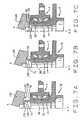
- Fig. 4 is a partial sectional view of an end portion prior to deformation into the formed end of Fig. 3;
- Fig. 5 is a front elevational view of the machine for deforming the end portion illustrated in Fig. 4 into the formed end illustrated in fig. 5.
- Fig. 6 is a sectional view of the machine taken along line 6-6 of Fig. 5; and
- Figs. 7A, B, and C are sectional views in elevation showing the tool for deforming the end portion and sequentially illustrating the deformations.
-
- Corresponding reference numerals will be used throughout the several figures of the drawings.
- The following detailed description illustrates the invention by way of example and not by way of limitation. This description will enable one skilled in the art to make an use the invention, and describes that which is presently believed to be the best mode of carrying out the invention.
- Referring now to the drawings, a hub assembly A (Fig. 1) for attaching a road wheel for a vehicle to the suspension system of the vehicle includes a
hub 2, ahousing 4 and abearing 6 which enables thehub 2 to rotate relative to thehousing 4 about an axis X of rotation with relatively little friction. A road wheel and a brake disk are attached to thehub 2, while thehousing 4 is secured firmly against a component of the suspension system for a vehicle. - The hub 2 (Fig. 1) has a
flange 10, ashort pilot diameter 12 on one side of theflange 10 and aspindle 14 on the other. Both thepilot diameter 12 and thespindle 14 lie along the axis X. Theflange 10 containslug bolts 16 which project axially from it in the direction of thepilot diameter 12, but lie radially outwardly from it. Thepilot diameter 12 functions as a pilot for aligning the wheel with thehub 2 as the wheel is advanced against theflange 10, to which it is secured with lug nuts that thread over thebolts 16. Thespindle 14 merges from ashoulder 18 set inwardly from the inside face of theflange 10 and terminates in a formedend 20 located at its opposite end. Thespindle 14 contains abore 22 which opens out of it at the formedend 20. - The
bearing 6 includes (Fig. 1) an inner race in the form of twocones 26 which fit around thespindle 14 where they are captured between theshoulder 18 and the formedend 20, there being an interference fit between eachcone 26 and thespindle 14. Eachcone 26 has atapered raceway 28 that is presented outwardly away from the axis X, athrust rib 30 at the large end of itsraceway 28, and backface 32 that is squared off with respect to the axis X on the end of thethrust rib 30. Theinboard cone 26 is somewhat longer than theoutboard cone 26 by reason of acylindrical cone extension 34 which projects beyond the small end of itsraceway 28. Theinboard cone 26 at itscone extension 34 abuts the small end of theoutboard cone 26 along thespindle 14, that is to say, the twocones 26 abut their front faces. Theback face 32 of theoutboard cone 26 abuts theshoulder 18 that lies immediately inwardly from theflange 10. The formedend 20 outwardly beyond theinboard cone 26 and lies against theback face 32 of that cone. Thus, the twocones 26 are captured on thespindle 14 between theshoulder 18 and the formedend 20. The twocones 26 abut their opposite ends, that is at their front faces, so that theextension 34 lies between theraceways 28 out of the twocones 26. - In addition to the
cones 26, thebearing 6 includestapered rollers 36 arranged in two rows, there being a separate row around eachcone 26. Actually, therollers 36 extend around theraceways 28 for thecones 26 with their tapered side faces along theraceways 28 and their large end face against thethrust ribs 30. Therollers 36 of each row are essentially on apex, which means that the envelopes in which their tapered side faces lie will have their apices located at a common point along the axis X. Each row ofrollers 36 has acage 38 to maintain the proper spacing between therollers 36 in that row. - The ring-
like housing 4 surrounds thespindle 14 as well as the twocones 26 and the two rows ofrollers 36. It forms part of thebearing 6 in that it has taperedraceways 40 which are presented inwardly toward the axis X. Indeed, thehousing 4 constitutes the outer race of thebearing 6. Theraceways 40 on thehousing 4 taper downwardly toward anintervening surface 42 which separates them. Therollers 36 likewise lie along theraceways 40 of thehousing 4, contacting theraceways 40 at their tapered side faces. At their large ends, theraceways 40 open into short end bores 44 in which the thrust ribs 30, of the twocones 26 are located. - Generally midway between its ends, the
housing 4 has a triangular flange 46 (Fig. 2) which fits against a component of a suspension system for a vehicle. Here the housing A is secured firmly to the suspension system component with bolts that engage threadedholes 47 located in the lobes of thetriangular flange 46. Along one of the edges of thetriangular flange 46 thehousing 4 contains a bore 48 (Fig. 1) which extends inwardly, obliquely to the axis X, and opens into the interior of thehousing 4 through theintervening surface 42. - The
oblique bore 48 contains aspeed sensor 50, the inner end of which is presented toward anexcitor ring 52 that fits over theextension 34 at the small end ofinboard cone 26. Thus, theexcitor ring 52 lies between the two rows ofrollers 36. Thering 52 has teeth or other disruptions which cause thesensor 50 to produce a pulsating signal as those disruptions move past the end of thesensor 50, and this of course occurs as thespindle 14 and thecones 26 around it rotate. The frequency of the signal reflects the angular velocity of thespindle 14 and indeed theentire hub 2. - The end bores 44 in the
housing 4 containseals 54 which fit around thethrust ribs 30 on thecones 26 to establish dynamic fluid barriers at the ends of thehousing 4. These barriers isolate therollers 36 and theraceways - The formed
end 20 lies behind theback face 32 of the inboard cone so that the twocones 26 are captured betweenshoulder 18 and the formedend 20 with their small ends in abutment. This not only retains thecone 26 in thespindle 14, but also retains thehousing 4 androllers 36 in place, this being attributable to the tapered geometry. In short, the formedend 20 unitizes the hub 5 assembly A. - More specifically, the formed
end 20 wraps around theinboard cone 26 at a profiled or curved inside comer 56 (Fig. 3) and immediately outwardly from thecorner 56 has a flat inside end face 58 that lies along theback face 32 of theinboard cone 26. On its opposite side, the formedend 20 has a curvedoutside end surface 60 which merges with a flatoutside end surface 62 that lies perpendicular to the axis X. The curvedoutside end surface 60 and the flatinside end face 58 are connected through a relatively sharp, yet curved,outside comer 64. The flatoutside end surface 62 merges into a firstbeveled surface 66 which lies at an oblique angle with respect to the axis X and thebeveled surface 66 merges into another secondbeveled surface 68 located at a somewhat steeper angle to the axis X. The steeperbeveled surface 68 leads into thebore 22. Theoutside comer 64 lies radially at or slightly inwardly from the large end of theraceway 28 on theinboard cone 26. The flatoutside end surface 62 provides a clamping surface for the hub assembly when clamped against a constant velocity joint or other such member. - The
hub 2 does not always have the formedend 20. Initially, it exists as a pre-form 70 (Fig. 4), which is the condition in which it forged and then machined. In the pre-form 70 thespindle 14 is straight, that is to say, its cylindrical exterior surface continues axially to the very end of thespindle 14. The twocones 26, therollers 36 of the two rows, andhousing 4, which is captured by therollers 36, are all installed over thestraight spindle 14 of the pre-form 70, leaving anend portion 71 of thespindle 14 projecting beyond theinboard cone 26. Thereupon, the projectingend portion 71 is deformed radially outwardly and axially into the formedend 20 in a rotary forming operation (Fig. 7). - In the pre-form 70, the
spindle 14 has (Fig. 4) the firstbeveled surface 68 that leads away from thebore 22. Thebeveled surface 68 merges into a slightly taperedsurface 72 at a comer or circle C of transition. The slightly taperedsurface 72 merges into another taperedsurface 74 leads of greater angle. The steeper taperedsurface 74 leads out to aflat end surface 78 with which it merges at acurved surface 80. Theflat end surface 78 at its periphery has achamfer 82. - That
end portion 71 of the pre-form 70 initially projects beyond theback face 32 of theinboard cone 26 without change in its external diameter, but is thereafter transformed into the formedend 20 in a rotary forming procedure. (Fig. 7). In this procedure the metal of theend portion 71 flows radially and axially, all without acquiring cracks, and ultimately assumes the configuration of the formedend 20. The transformation occurs in a rotary forming machine B. - The rotary forming machine B includes (Figs. 5 and 6) a
frame 90 which carries a table 92 that rotates about a vertical axis Y. Actually, the table 92 rotates on a base 94 with the power for producing the rotation being supplied by a motor, either electric or hydraulic, that is in thebase 94. Thebase 94 followsvertical ways 96 on theframe 90, with this translational movement deriving from aram 98 that is located between the bottom of theframe 90 and thebase 94. Theram 98 contains a load cell for measuring the force exerted by it. The table 92 has an upwardly presented surface out of which asocket 100 opens, and thesocket 100 is configured to receive thepilot diameter 12 and theflange 10 of the pre-form 70, with the axis X of the pre-form 70 coinciding with the axis Y of rotation for the table 92, and with thespindle 14 projecting upwardly. Thesocket 100 also receives thelug bolts 16 as well, and they engage the pre-form 70 with the table 92 such that the pre-form 70, when on the table 92, will rotate with the table 92 without slipping. - The machine B also includes a
cross head 110 which is mounted on theframe 90 by means oftrunnions 112, the common axis Z of which intersects the axis Y for the table 92 at a right angle. Thecross head 110 has aspindle 114 which rotates about an axis S that intersects the trunnion axis Z and the table axis Y, with its inclination as to the axis Y being variable and dependent on the position of thecross head 110. That position is controlled by anelectric screw jack 116 which is connected between thecross head 110 and theframe 90. Thecross head 100 carries a motor, either electric or hydraulic, which rotates thespindle 114. - At its lower end, the
spindle 114 has a formingtool 120 attached to it, and thetool 120 has a contoured face 122 (Fig.7) that is presented toward the table 92 so that it will bear against theend portion 71 of thespindle 14 on the pre-form 70 as the table 92 is elevated. The contour leaves thetool 120 with aperipheral rib 124 and a depressed center region having aflat surface 126 that merges with therib 124 along anarcuate surface 128 which matches the curvature of thecurved end surface 60 on the formedend 20. - Finally, the machine B has a restraining
arm 140 which at one end is attached to apost 142 that rises from the base 94 to an elevation above the table 92. At its other end thearm 140 is configured to fit against one of theflanges 46 of thehousing 4 for the particular hub assembly A that is in thesocket 100 of the table 92. Thearm 140 prevents thehousing 4 from rotating with thehub 2 when the table 92 revolves. Under the circumstances theflange 46 ofhousing 4 serves as a torque arm. The restrainingarm 140 extends over the table 92 generally perpendicular to the torque arm formed byflange 46 and contains asensor 144 for measuring the force exerted on thearm 140 byflange 46 of thehousing 4. Hence, thesensor 144 enables one to measure the torque exerted on thehousing 4 by the rotatinghub 2. - In order to complete the hub assembly A from its component parts, some of the parts first require preassembly. For example the
bolts 16 are fitted to theflange 10 on the hub 2 - or more accurately to theflange 10 on the pre-form 70 that eventually becomes thehub 2. Also, theseal 54 is pressed over therib 30 of theoutboard cone 26. Thereupon, theoutboard cone 26 is pressed over thestraight spindle 14 on the pre-form 70 to its fullest extent, that is until itsback face 32 abuts theshoulder 18 at the end of thespindle 14. After a lubricant is applied to theoutboard cone 26 and therollers 36 which surround it, thehousing 4 is lowered overoutboard cone 26 and its row ofrollers 34 and aligned withseal 26 on theoutboard cone 26. Further advancement forces theseal 26 into the outboard end bore 44 and seats therollers 36 against theoutboard raceway 40 of thehousing 4. Next theinboard cone 26 is pressed over thespindle 14 of the pre-form 70 until theextension 34 at its small end comes against the end of theoutboard cone 26. This positions theexitor ring 52 within the interveningsurface 42 of thehousing 4 and seats therollers 34 that surround theinboard cone 26 against theinboard raceway 40 of thehousing 4. Moreover, for all intents and purposes, it brings thebearing 6 which is so formed to the proper setting. At this time theinboard seal 54 may be pressed into the inboard end bore 44 of thehousing 4 and over thethrust 30 of theinboard cone 26. At this juncture in the assembly procedure, theend portion 71 on thespindle 14 of the pre-form 70 projects well beyond theback face 32 of theinboard cone 26. - Once the
housing 4 andbearing 6 have been fitted to the pre-form 70, the partially completed assembly is transferred to the machine B to permanently unite thehub 2,housing 4 andbearing 6. In this regard, the pre-form 70 that becomes thehub 2 is fitted to thesocket 100 in the table 92 of the machine B with thepilot diameter 12 on the pre-form 70 presented downwardly and serving to position the pre-form 70 with its axis X coinciding with the axis Y of rotation for the table 92. Thebolts 16 in theflange 10 of the pre-form 70 project downwardly, engaging the table 92, so that when the table 92 revolves, the pre-form 70 rotates without slipping. - The table 92 does indeed revolve, it being turned by the motor in the
base 94. The formingtool 120 likewise turns in the same direction, although at a lesser velocity, and it is powered by the motor in thecrosshead 110. Next theram 98 is energized, and it elevates the rotating table 92 and the partially assembled hub assembly A that is on it. Theextended end portion 71 of thespindle 14 comes against the rotating formingtool 120 of thecrosshead 110, and thetool 120 deforms thatend portion 71 to displace the metal that is in it radially outwardly and axially toward thecone 26. This deformation creates the formed end or 20. Theend portion 71 is thus subjected to both radial and axial deformation which in turn produces desirable work hardening of theend portion 71 as enabling the formation of both curved and flat outer surfaces on the formed end with a reduced risk fracture. - More specifically, the
end portion 71 of thespindle 14 aligns with theflat surface 126 on the contouredface 122 of thetool 120, and as thespindle 14 advances along the axis Y, theflat end surface 78 on theend portion 71 comes againstflat surface 126 of thetool 120. Continued advancement of thespindle 14 causes theend portion 71 also to turn radially outwardly toward thearcuate surface 128 on theface 122 of thetool 120. As a consequence, the taperedsurface 74 and thereafter the taperedsurface 72 on theend portion 71 come against theflat surface 126 of thetool 120. Eventually, with continued advancement of theend portion 71 into thetool 120, theend portion 71 deforms outwardly to assume the configuration ofarcuate surface 128, while the adjoining region becomes flat, owing to its presence against theflat surface 126 on thetool 120. This accounts for thecurved end surface 60 and the adjacentflat surface 62 on the formedend 20 that is imparted to thespindle 14. - The
ram 98 does not advance thespindle 14 into thetool 120 at a constant velocity. Initially, the velocity is greater than near the end. Thus, theram 98 advances more slowly as it works the metal of theend portion 71 against and along theback face 32 of theinboard cone 26. Moreover, as theram 98 advances, the force exerted by it is registered by the load cell in theram 98 and is monitored. Theram 98 dwells after the final increment of advance to insure that the formedend 20 formed by thetool 120 retains the desired configuration. For ahub 2 with itsspindle 14 having a 45 mm outside diameter, the force exerted by theram 98 preferably should be between 6 and 8 tonnes and should not exceed 10 to 12 tonnes. - The forming
tool 120, as thespindle 14 on the pre-form 70 advances into it, causes the metal of the pre-form 70 to displace gradually or, in other words, flow. To this end, the metal of the pre-form 70 must have sufficient ductility to undergo the flow without developing cracks or fissures. 1040 steel which has a sulfur content less than 0.05% by weight and preferably less than 0.02% has this capacity. The deformation work hardens the steel, so the hardness of the formedend 20 is somewhat greater than the hardness of the remainder of thehub 2. - The configuration of the extended
portion 71 of the pre-form 70, the distance it projects beyond theback face 32 of theinboard cone 26, and advance imparted to the table 92 by theram 98 are all such that the formedend 20 does not deform theinboard cone 26 or impart excessive preload to thebearing 6. For example, if theend portion 71 of the pre-form 70 extends too far beyond theback face 32 of theinboard cone 26 or otherwise contains excessive material in that region, the space between the forming tool and the cone back face 32 cannot accommodate all of the material, and theinboard cone 26 undergoes distortion in the region of itsthrust rib 30 andraceway 28. Likewise, if the dwell height of theram 98 is too high, again inadequate space exists to contain the metal which flows along the cone back face 32 and thecone 26 will experience distortion. - Visual inspections of the formed
end 20 will not reveal if it has distorted theinboard cone 26. But the torque in thebearing 6 will, and thesensor 144 in therestraining arm 140 in effect measures that torque. Moreover, thesensor 144 reveals the torque without having to remove the hub assembly A to another fixture for a separate test, and thus immediately identifies a hub assembly A which should be rejected. For abearing 6 that fits around ahub spindle 14 with a 45 mm diameter, the maximum torque in the bearing should not exceed 35 to 40 in-lbs. The change in torque during the rotary forming should not exceed 8 to 10 in-Ibs. - The force registered by the load cell in the
ram 98 also serves to identify bearing assemblies that require rejection. In this regard, excessive force exerted by the ram indicates an error in the geometry of the pre-form 71 or perhaps, an error in setting up the machine B. In any event, excessive force exerted by theram 98 may distort theinboard cone 26, causing permanent damage to the bearing assembly A. For ahub 2 having aspindle 14 with a 45 mm outside diameter, a ram force exceeding 10 to 12 tonnes signals a possible defect. - The restraining
arm 140 not only facilitates measurement of the torque, but it also holds thehousing 2 fixed while thehub 2 androllers 36 rotate within it. This seats the rollers along theraceways 28 and against thethrust ribs 30 of the twocones 26 and also seats them along theraceways 40 of thehousing 4. It further prevents brinnelling of theraceways - In lieu of the
outboard cone 26 being a separate component, it may be integrated into thehub 2. In other words, the outboardinner raceway 28 may be formed directly on thespindle 14, just as theouter raceways 40 are formed directly on thehousing 4. On the other hand, theouter raceways 40 may be formed on separate races or cups fitted into thehousing 4. The rolling elements need not be taperedrollers 36, but may be balls or other rolling elements well known in the art, and of course the raceways in that instance would conform to them, yet preferably remain oblique to the axis. - In view of the above, it will be seen that the several advantages of the present invention have been achieved and other advantageous results have been obtained.
- It is intended that all matter contained in the above description or shown in the accompanying drawings shall be interpreted as illustrative and not in a limiting sense as various changes could be made in the above constructions without departing from the scope of the invention as defined by the appended claims.
Claims (9)
- Process for securing a component (6) on a spindle (14), the component (6) having an opening in which the spindle (14) is received, the spindle (14) having a deformable spindle annular end portion (71) extending beyond the opening, the spindle annular end portion (71) being engaged with a forming tool (120) that is rotatable about a tool axis (S) that is inclined to the spindle axis (Y) characterised in that the spindle (14) and component (6) rotate in the same rotational direction as the forming tool (120) to gradually deform the spindle annular end portion (71) generally radially outwardly and axially and create a formed end (20) that lies against an end face (32) of the component (6) to secure the component (6) on the spindle (14), and in that at least one of the forming tool (120) and the spindle (14) is moved toward the other at at least two different velocities including a first velocity during the initial stage of the forming operation and at another velocity that is slower than the first velocity in the final stages of the forming operation during which the formed end (20) is worked against the end face of the component.
- The process of claim 1 wherein the spindle end portion (71) is engaged with the forming tool (120) by linearly moving the spindle axially toward the forming tool (120) which remains in an essentially fixed position.
- Apparatus for securing a component (6) on a spindle (14), the component (6) having an opening in which the spindle (14) is received, the spindle (14) having a deformable spindle annular end portion (71) extending beyond the opening, the apparatus comprising: a rotatable spindle support (92) that supports the spindle (14) and is rotatable about the spindle axis (Y); a forming tool (120) that is rotatable about a tool axis (S) that is inclined to the spindle axis (Y); a linear actuator (98) that linearly moves at least one of the spindle support (92) and the forming tool (120) toward the other to engage the spindle annular end portion (71) with the forming tool (120) characterised in that the spindle (14) and component (6) rotate in the same rotational direction as the forming tool (120) to gradually deform the spindle annular end portion (71) generally radially outwardly and axially and create a formed end (20) that lies against an end face (32) of the component (6), and in that the linear actuator (98) linearly moves at least one of the spindle support (92) and the forming tool (120) toward the other at at least two different velocities including a first velocity during the initial stage of the forming operation and at another velocity that is slower than the first velocity in the final stages of the forming operation during which the formed end (20) is worked against the end face (32) of the component (6).
- The apparatus of claim 3 including a forming tool adjusting device (116) for adjusting the inclination angle of the tool axis (S).
- The apparatus of any of claims 3 or 4 wherein the linear actuator (98) linearly moves the spindle support (92) toward the forming tool (120) which remains in an essentially fixed position.
- The apparatus of any of claims 3 to 5 including a force monitoring device that monitors the magnitude of the force with which the spindle (14) and forming tool (120) engage one another.
- The apparatus of any of claims 3 to 6 wherein the linear actuator (98) provides a force of engagement between the spindle end portion (71) and the forming tool (120) that does not exceed 12 tonnes.
- The apparatus of any of claims 3 to 6 wherein the linear actuator (98) provides a force of engagement between the spindle end portion (71) and the forming tool (120) that does not exceed 8 tonnes.
- The apparatus of any of claims 3 to 6 wherein the linear actuator (98) provides a force of engagement between the spindle end portion (71) and the forming tool (120) that is between 6 - 8 tonnes.
Applications Claiming Priority (3)
| Application Number | Priority Date | Filing Date | Title |
|---|---|---|---|
| GB9713343 | 1997-06-24 | ||
| GBGB9713343.3A GB9713343D0 (en) | 1997-06-24 | 1997-06-24 | Process and machine for uniting rotatable machine components |
| EP98930921A EP0991494B1 (en) | 1997-06-24 | 1998-06-22 | Process and machine for uniting rotatable machine components |
Related Parent Applications (1)
| Application Number | Title | Priority Date | Filing Date |
|---|---|---|---|
| EP98930921A Division EP0991494B1 (en) | 1997-06-24 | 1998-06-22 | Process and machine for uniting rotatable machine components |
Publications (3)
| Publication Number | Publication Date |
|---|---|
| EP1179384A2 EP1179384A2 (en) | 2002-02-13 |
| EP1179384A3 EP1179384A3 (en) | 2002-08-28 |
| EP1179384B1 true EP1179384B1 (en) | 2004-03-17 |
Family
ID=10814866
Family Applications (4)
| Application Number | Title | Priority Date | Filing Date |
|---|---|---|---|
| EP01126764A Expired - Lifetime EP1179384B1 (en) | 1997-06-24 | 1998-06-22 | Process and machine for uniting rotatable machine components |
| EP01126765A Expired - Lifetime EP1179385B1 (en) | 1997-06-24 | 1998-06-22 | Process and machine for uniting rotatable machine components |
| EP01126767A Expired - Lifetime EP1179386B1 (en) | 1997-06-24 | 1998-06-22 | Process and machine for rotatable machine components |
| EP98930921A Expired - Lifetime EP0991494B1 (en) | 1997-06-24 | 1998-06-22 | Process and machine for uniting rotatable machine components |
Family Applications After (3)
| Application Number | Title | Priority Date | Filing Date |
|---|---|---|---|
| EP01126765A Expired - Lifetime EP1179385B1 (en) | 1997-06-24 | 1998-06-22 | Process and machine for uniting rotatable machine components |
| EP01126767A Expired - Lifetime EP1179386B1 (en) | 1997-06-24 | 1998-06-22 | Process and machine for rotatable machine components |
| EP98930921A Expired - Lifetime EP0991494B1 (en) | 1997-06-24 | 1998-06-22 | Process and machine for uniting rotatable machine components |
Country Status (7)
| Country | Link |
|---|---|
| US (2) | US6443622B1 (en) |
| EP (4) | EP1179384B1 (en) |
| JP (2) | JP3370098B2 (en) |
| AU (1) | AU8119798A (en) |
| DE (4) | DE69823709T2 (en) |
| GB (1) | GB9713343D0 (en) |
| WO (1) | WO1998058762A1 (en) |
Families Citing this family (52)
| Publication number | Priority date | Publication date | Assignee | Title |
|---|---|---|---|---|
| DE69831515T2 (en) | 1997-01-17 | 2006-06-14 | Nsk Ltd | Bearing unit for a vehicle wheel suspension |
| DE69932782T2 (en) * | 1998-09-11 | 2007-12-27 | Jtekt Corp., Osaka | bearing device |
| JP2000343905A (en) * | 1999-06-02 | 2000-12-12 | Nsk Ltd | Assembling method for wheel-supporting rolling bearing unit |
| US6415508B1 (en) | 1999-06-09 | 2002-07-09 | The Timken Company | Hub assembly having minimum runout and process for producing the same |
| JP4123643B2 (en) * | 1999-06-21 | 2008-07-23 | 株式会社ジェイテクト | Axial force management method |
| US6299360B1 (en) | 1999-08-25 | 2001-10-09 | The Timken Company | Hub assembly having a captured ring and process for assembling the same |
| FR2800324B1 (en) * | 1999-10-29 | 2002-01-11 | Peugeot Citroen Automobiles Sa | RUNNING TRAIN WITH SERTI BEARING |
| EP1111257B1 (en) * | 1999-12-20 | 2003-09-10 | Nsk Ltd | Wheel-support rolling bearing unit and method of manufacturing the same |
| US6464399B1 (en) * | 1999-12-27 | 2002-10-15 | The Timken Company | Hub assembly for automotive vehicles |
| JP2001347805A (en) * | 2000-04-05 | 2001-12-18 | Nsk Ltd | Axle unit for driving wheel |
| US6485188B1 (en) | 2000-04-21 | 2002-11-26 | The Timken Company | Wheel mounting with a bearing race embedded in a cast component |
| JP2002225503A (en) * | 2000-11-29 | 2002-08-14 | Nsk Ltd | Method of producing hub unit for supporting wheel and pressing die for producing the same |
| JP2003148499A (en) * | 2000-12-05 | 2003-05-21 | Koyo Seiko Co Ltd | Bearing device for vehicle |
| JP2007321988A (en) * | 2000-12-05 | 2007-12-13 | Jtekt Corp | Vehiclular bearing apparatus |
| JP2002250358A (en) | 2000-12-18 | 2002-09-06 | Nsk Ltd | Rolling bearing unit for supporting wheel |
| US6460423B1 (en) * | 2001-02-01 | 2002-10-08 | The Timken Company | Method of measuring preload in a multirow bearing assembly |
| KR20030094277A (en) | 2001-03-06 | 2003-12-11 | 더 팀켄 컴퍼니 | Installation of a Hub/Bearing Assembly for an Automotive Vehicle |
| FR2822754B1 (en) * | 2001-03-28 | 2003-07-18 | Roulements Soc Nouvelle | ROLLING BEARING ASSEMBLY PROVIDED WITH AN INFORMATION SENSOR DEVICE |
| US6575476B2 (en) | 2001-06-27 | 2003-06-10 | The Timken Company | Chuck for holding a hub assembly |
| US6512365B1 (en) | 2001-07-10 | 2003-01-28 | The Timken Company | Sensor for monitoring angular velocity |
| FR2827202B1 (en) * | 2001-07-13 | 2003-09-12 | Roulements Soc Nouvelle | PROCESS FOR PRODUCING A RETAINING COLLAR, PARTICULARLY FOR RETAINING A BEARING ON A WHEEL HUB |
| FR2829724B1 (en) * | 2001-09-18 | 2003-12-19 | Peugeot Citroen Automobiles Sa | RUNNING DEVICE WITH FASTENING CLIP |
| JP2003120703A (en) * | 2001-10-16 | 2003-04-23 | Nsk Ltd | Rotation support device for driving wheel with rotation detecting device |
| US6532666B1 (en) * | 2001-11-29 | 2003-03-18 | The Timken Company | Process for capturing a bearing race on a spindle |
| JP2003211908A (en) * | 2002-01-18 | 2003-07-30 | Koyo Seiko Co Ltd | Rolling bearing device |
| US6811003B2 (en) * | 2002-02-28 | 2004-11-02 | The Tinken Company | Wheel mounting |
| JP4127266B2 (en) * | 2002-06-24 | 2008-07-30 | 日本精工株式会社 | Manufacturing method and manufacturing apparatus for rolling bearing unit for supporting wheel |
| EP1880113A1 (en) * | 2005-05-10 | 2008-01-23 | The Timken Company | Bearing assembly with integrated sensor system |
| JP3970890B2 (en) * | 2005-05-12 | 2007-09-05 | Ntn株式会社 | Wheel bearing device |
| EP1722115B1 (en) | 2005-05-12 | 2015-10-07 | NTN Corporation | Wheel support bearing assembly |
| US20070025654A1 (en) * | 2005-07-26 | 2007-02-01 | Koyo Seiko Co., Ltd. | Tapered roller bearing assembly and method of fabricating the same |
| US20070116397A1 (en) | 2005-11-18 | 2007-05-24 | The Timken Company | Unitized bearing assembly and method of assembling the same |
| US20080298732A1 (en) * | 2005-12-21 | 2008-12-04 | The Timken Company | Unitized Single Row Bearing with Reverse Thrust Capabilities |
| WO2007073483A1 (en) * | 2005-12-21 | 2007-06-28 | The Timken Company | Wheel end with coupler |
| WO2007089642A1 (en) * | 2006-01-26 | 2007-08-09 | The Timken Company | Wheel end |
| WO2007103915A2 (en) * | 2006-03-06 | 2007-09-13 | The Timken Company | A load sensing wheel end |
| US7686313B2 (en) * | 2006-04-26 | 2010-03-30 | The Timken Company | Wheel end vented through sensor cable |
| WO2007134157A2 (en) | 2006-05-10 | 2007-11-22 | The Timken Company | Driving wheel assembly |
| JP4829170B2 (en) * | 2007-04-26 | 2011-12-07 | 株式会社ジェイテクト | Hub unit |
| US7699405B2 (en) * | 2007-08-24 | 2010-04-20 | The Timken Company | Vehicle wheel end assemblies and methods of assembly thereof |
| WO2009089420A1 (en) * | 2008-01-10 | 2009-07-16 | The Timken Company | Compact wheel end and corner module |
| JP4760856B2 (en) * | 2008-05-26 | 2011-08-31 | 株式会社ジェイテクト | Axle bearing device |
| JP5304742B2 (en) * | 2010-07-26 | 2013-10-02 | 株式会社ジェイテクト | Manufacturing method of hub unit |
| US8616779B2 (en) | 2010-11-29 | 2013-12-31 | Honda Motor Co., Ltd. | Shortened driveshaft stem |
| WO2012159779A1 (en) * | 2011-05-23 | 2012-11-29 | Schaeffler Technologies AG & Co. KG | Rolling bearing arrangement with clamping means which support a positive locking action |
| ITTO20110702A1 (en) * | 2011-07-29 | 2013-01-30 | Skf Ab | METHOD FOR FORMING A FRONT DENTAL ON AN INTERNAL RING OF A WHEEL HUB |
| KR101322429B1 (en) * | 2011-11-30 | 2013-10-28 | 주식회사 일진베어링 | Wheel bearing assembly |
| ITTO20130023A1 (en) * | 2013-01-11 | 2014-07-12 | Skf Ab | LIGHT WEIGHT HUB UNIT WITH INTEGRATED BEARING RINGS, AND PROCEDURE FOR ITS MANUFACTURING |
| ITTO20130027A1 (en) * | 2013-01-11 | 2014-07-12 | Skf Ab | UNIT OF LIGHT WEIGHT HUB WITH INTEGRATED BEARING RINGS, AND PROCEDURES FOR ITS MANUFACTURING |
| JP6850214B2 (en) | 2016-08-08 | 2021-03-31 | Thk株式会社 | Mobile holders and mobiles |
| CN108202204B (en) * | 2016-12-16 | 2020-01-21 | 沈阳铸造研究所 | Spinning forming method of high-corrosion-resistance charging basket for ceramic core high-temperature high-pressure depoling device |
| JP6974971B2 (en) | 2017-07-14 | 2021-12-01 | 株式会社ジェイテクト | Bearing unit manufacturing equipment and bearing unit manufacturing method |
Family Cites Families (18)
| Publication number | Priority date | Publication date | Assignee | Title |
|---|---|---|---|---|
| US3451243A (en) | 1966-08-03 | 1969-06-24 | Galaxie Mfg Co | Process for forming serrated flanged pipe |
| NL140620B (en) | 1968-04-10 | 1973-12-17 | Skf Svenska Kullagerfab Ab | AXLE CONSTRUCTION FOR A NON-DRIVEN WHEEL OF A MOTOR VEHICLE. |
| NL6805109A (en) | 1968-04-10 | 1969-10-14 | ||
| CH507036A (en) * | 1969-04-11 | 1971-05-15 | Braecker Ag | Device for forming locking heads on rivets |
| DE3418440A1 (en) | 1984-05-18 | 1985-11-21 | FAG Kugelfischer Georg Schäfer KGaA, 8720 Schweinfurt | Wheel bearing unit with positively engaging connection of two annular parts which can be fitted one into the other |
| NL8403209A (en) | 1984-10-22 | 1986-05-16 | Skf Ind Trading & Dev | ROLLER BEARING CONSTRUCTION. |
| DE3636243A1 (en) | 1986-10-24 | 1988-05-11 | Loehr & Bromkamp Gmbh | WHEEL BEARING (NY) SMOOTH JOINT UNIT |
| DE3920299A1 (en) | 1989-06-21 | 1991-01-03 | Kugelfischer G Schaefer & Co | WHEEL BEARING FOR MOTOR VEHICLES |
| EP0405033A1 (en) * | 1989-06-30 | 1991-01-02 | Vsi Corporation | Engine clip bolt |
| US5061090A (en) | 1990-05-31 | 1991-10-29 | Porter-Cable Corporation | Shaft and bearing assembly |
| FR2666389B1 (en) * | 1990-09-04 | 1992-10-23 | Roulements Soc Nouvelle | PROCESS FOR PRODUCING A BEARING COLLAR AND BEARING ASSEMBLY EQUIPPED WITH SUCH A COLLAR. |
| DE4134434C2 (en) | 1991-10-18 | 1993-12-02 | Kugelfischer G Schaefer & Co | Wheel bearing unit with a speed determination device |
| US5355722A (en) | 1993-05-11 | 1994-10-18 | Socier Jerry C | Conduit flaring apparatus |
| DE4335793C2 (en) | 1993-10-20 | 1998-04-09 | Kugelfischer G Schaefer & Co | Method and device for assembling a bearing unit, preferably a wheel bearing unit for motor vehicles |
| DE4339847C2 (en) * | 1993-11-23 | 2000-09-14 | Kugelfischer G Schaefer & Co | Storage unit |
| DE4400773A1 (en) | 1994-01-13 | 1995-07-20 | Teves Metallwaren Alfred | Wheel bearing unit with revolution rate sensor |
| US5603554A (en) * | 1996-02-21 | 1997-02-18 | Chrysler Corporation | Rear axle assembly |
| AU6012398A (en) * | 1996-12-10 | 1998-07-03 | Kelsey-Hayes Company | Vehicle wheel hub and bearing retention system and method for producing same |
-
1997
- 1997-06-24 GB GBGB9713343.3A patent/GB9713343D0/en active Pending
-
1998
- 1998-06-22 DE DE69823709T patent/DE69823709T2/en not_active Expired - Lifetime
- 1998-06-22 EP EP01126764A patent/EP1179384B1/en not_active Expired - Lifetime
- 1998-06-22 DE DE69822524T patent/DE69822524T2/en not_active Expired - Lifetime
- 1998-06-22 DE DE69809234T patent/DE69809234T2/en not_active Expired - Lifetime
- 1998-06-22 JP JP50400999A patent/JP3370098B2/en not_active Expired - Lifetime
- 1998-06-22 EP EP01126765A patent/EP1179385B1/en not_active Expired - Lifetime
- 1998-06-22 WO PCT/GB1998/001823 patent/WO1998058762A1/en active IP Right Grant
- 1998-06-22 US US09/446,671 patent/US6443622B1/en not_active Expired - Lifetime
- 1998-06-22 EP EP01126767A patent/EP1179386B1/en not_active Expired - Lifetime
- 1998-06-22 AU AU81197/98A patent/AU8119798A/en not_active Abandoned
- 1998-06-22 DE DE69825921T patent/DE69825921T2/en not_active Expired - Lifetime
- 1998-06-22 EP EP98930921A patent/EP0991494B1/en not_active Expired - Lifetime
-
2002
- 2002-07-11 US US10/193,542 patent/US6688773B2/en not_active Expired - Lifetime
- 2002-09-09 JP JP2002263432A patent/JP3582730B2/en not_active Expired - Lifetime
Also Published As
| Publication number | Publication date |
|---|---|
| EP0991494A1 (en) | 2000-04-12 |
| DE69822524D1 (en) | 2004-04-22 |
| DE69825921D1 (en) | 2004-09-30 |
| JP3582730B2 (en) | 2004-10-27 |
| US20020172439A1 (en) | 2002-11-21 |
| DE69823709D1 (en) | 2004-06-09 |
| DE69825921T2 (en) | 2005-09-08 |
| EP1179385A3 (en) | 2002-09-04 |
| EP1179386A2 (en) | 2002-02-13 |
| EP1179385B1 (en) | 2004-05-06 |
| EP1179386A3 (en) | 2002-09-04 |
| DE69822524T2 (en) | 2005-03-03 |
| JP2000513661A (en) | 2000-10-17 |
| US6688773B2 (en) | 2004-02-10 |
| GB9713343D0 (en) | 1997-08-27 |
| WO1998058762A1 (en) | 1998-12-30 |
| EP1179386B1 (en) | 2004-08-25 |
| JP3370098B2 (en) | 2003-01-27 |
| EP0991494B1 (en) | 2002-11-06 |
| EP1179384A3 (en) | 2002-08-28 |
| DE69809234D1 (en) | 2002-12-12 |
| US6443622B1 (en) | 2002-09-03 |
| DE69809234T2 (en) | 2003-08-28 |
| EP1179385A2 (en) | 2002-02-13 |
| JP2003181571A (en) | 2003-07-02 |
| EP1179384A2 (en) | 2002-02-13 |
| AU8119798A (en) | 1999-01-04 |
| DE69823709T2 (en) | 2005-04-21 |
Similar Documents
| Publication | Publication Date | Title |
|---|---|---|
| EP1179384B1 (en) | Process and machine for uniting rotatable machine components | |
| US5494358A (en) | Package bearing | |
| US6640438B2 (en) | Process and machine for uniting rotatable machine components | |
| US6485188B1 (en) | Wheel mounting with a bearing race embedded in a cast component | |
| US6761486B2 (en) | Rolling bearing unit for supporting vehicle wheel | |
| US6247219B1 (en) | Method for producing a vehicle hub, bearing and brake disc assembly | |
| US6158124A (en) | Preloading & machining mounted brake disc | |
| US5937499A (en) | Machining brake disc without moment load on bearing | |
| CN103389207B (en) | Method of inspecting wheel hub unit | |
| US20070116397A1 (en) | Unitized bearing assembly and method of assembling the same | |
| US5915502A (en) | Brake disc assembly and a method for fabricating brake disc | |
| EP1448906B1 (en) | Process for capturing a bearing race on a spindle | |
| US20050231025A1 (en) | Wheel support rolling bearing unit and manufacturing method therefor | |
| US4878683A (en) | Unitary hub assembly | |
| JP4710179B2 (en) | Manufacturing method of bearing unit for wheel drive wheel | |
| EP1470936A1 (en) | Bearing unit for vehicle wheel | |
| EP1470935A1 (en) | Bearing unit for vehicle wheel | |
| JP2022028477A (en) | Hub unit bearing and manufacturing method thereof, and vehicle and manufacturing method thereof | |
| WO2003057512A1 (en) | Unitized wheel end |
Legal Events
| Date | Code | Title | Description |
|---|---|---|---|
| PUAI | Public reference made under article 153(3) epc to a published international application that has entered the european phase |
Free format text: ORIGINAL CODE: 0009012 |
|
| 17P | Request for examination filed |
Effective date: 20011109 |
|
| AC | Divisional application: reference to earlier application |
Ref document number: 991494 Country of ref document: EP |
|
| AK | Designated contracting states |
Kind code of ref document: A2 Designated state(s): DE FR GB SE |
|
| PUAL | Search report despatched |
Free format text: ORIGINAL CODE: 0009013 |
|
| RIN1 | Information on inventor provided before grant (corrected) |
Inventor name: SMITH, DOUGLAS H. Inventor name: HOLLAND, PETER Inventor name: WEBB, ALAN CHARLES Inventor name: STANDRING, PETER Inventor name: BAHNEY, LARRY L. |
|
| AK | Designated contracting states |
Kind code of ref document: A3 Designated state(s): DE FR GB SE |
|
| AKX | Designation fees paid |
Designated state(s): DE FR GB SE |
|
| GRAP | Despatch of communication of intention to grant a patent |
Free format text: ORIGINAL CODE: EPIDOSNIGR1 |
|
| RIN1 | Information on inventor provided before grant (corrected) |
Inventor name: SMITH, DOUGLAS H. Inventor name: WEBB, ALAN CHARLES Inventor name: HOLLAND, PETER Inventor name: STANDRING, PETER Inventor name: BAHNEY, LARRY L. |
|
| GRAS | Grant fee paid |
Free format text: ORIGINAL CODE: EPIDOSNIGR3 |
|
| GRAA | (expected) grant |
Free format text: ORIGINAL CODE: 0009210 |
|
| AC | Divisional application: reference to earlier application |
Ref document number: 0991494 Country of ref document: EP Kind code of ref document: P |
|
| AK | Designated contracting states |
Kind code of ref document: B1 Designated state(s): DE FR GB SE |
|
| REG | Reference to a national code |
Ref country code: GB Ref legal event code: FG4D |
|
| REF | Corresponds to: |
Ref document number: 69822524 Country of ref document: DE Date of ref document: 20040422 Kind code of ref document: P |
|
| REG | Reference to a national code |
Ref country code: SE Ref legal event code: TRGR |
|
| ET | Fr: translation filed | ||
| PLBE | No opposition filed within time limit |
Free format text: ORIGINAL CODE: 0009261 |
|
| STAA | Information on the status of an ep patent application or granted ep patent |
Free format text: STATUS: NO OPPOSITION FILED WITHIN TIME LIMIT |
|
| 26N | No opposition filed |
Effective date: 20041220 |
|
| REG | Reference to a national code |
Ref country code: FR Ref legal event code: PLFP Year of fee payment: 19 |
|
| REG | Reference to a national code |
Ref country code: FR Ref legal event code: PLFP Year of fee payment: 20 |
|
| PGFP | Annual fee paid to national office [announced via postgrant information from national office to epo] |
Ref country code: DE Payment date: 20170621 Year of fee payment: 20 Ref country code: GB Payment date: 20170620 Year of fee payment: 20 Ref country code: FR Payment date: 20170621 Year of fee payment: 20 |
|
| PGFP | Annual fee paid to national office [announced via postgrant information from national office to epo] |
Ref country code: SE Payment date: 20170620 Year of fee payment: 20 |
|
| REG | Reference to a national code |
Ref country code: DE Ref legal event code: R071 Ref document number: 69822524 Country of ref document: DE |
|
| REG | Reference to a national code |
Ref country code: GB Ref legal event code: PE20 Expiry date: 20180621 |
|
| PG25 | Lapsed in a contracting state [announced via postgrant information from national office to epo] |
Ref country code: GB Free format text: LAPSE BECAUSE OF EXPIRATION OF PROTECTION Effective date: 20180621 |