EP1448906B1 - Process for capturing a bearing race on a spindle - Google Patents
Process for capturing a bearing race on a spindle Download PDFInfo
- Publication number
- EP1448906B1 EP1448906B1 EP02756829A EP02756829A EP1448906B1 EP 1448906 B1 EP1448906 B1 EP 1448906B1 EP 02756829 A EP02756829 A EP 02756829A EP 02756829 A EP02756829 A EP 02756829A EP 1448906 B1 EP1448906 B1 EP 1448906B1
- Authority
- EP
- European Patent Office
- Prior art keywords
- spindle
- force
- phase
- forming tool
- criteria
- Prior art date
- Legal status (The legal status is an assumption and is not a legal conclusion. Google has not performed a legal analysis and makes no representation as to the accuracy of the status listed.)
- Expired - Lifetime
Links
Images


Classifications
-
- F—MECHANICAL ENGINEERING; LIGHTING; HEATING; WEAPONS; BLASTING
- F16—ENGINEERING ELEMENTS AND UNITS; GENERAL MEASURES FOR PRODUCING AND MAINTAINING EFFECTIVE FUNCTIONING OF MACHINES OR INSTALLATIONS; THERMAL INSULATION IN GENERAL
- F16C—SHAFTS; FLEXIBLE SHAFTS; ELEMENTS OR CRANKSHAFT MECHANISMS; ROTARY BODIES OTHER THAN GEARING ELEMENTS; BEARINGS
- F16C19/00—Bearings with rolling contact, for exclusively rotary movement
- F16C19/22—Bearings with rolling contact, for exclusively rotary movement with bearing rollers essentially of the same size in one or more circular rows, e.g. needle bearings
- F16C19/34—Bearings with rolling contact, for exclusively rotary movement with bearing rollers essentially of the same size in one or more circular rows, e.g. needle bearings for both radial and axial load
- F16C19/38—Bearings with rolling contact, for exclusively rotary movement with bearing rollers essentially of the same size in one or more circular rows, e.g. needle bearings for both radial and axial load with two or more rows of rollers
- F16C19/383—Bearings with rolling contact, for exclusively rotary movement with bearing rollers essentially of the same size in one or more circular rows, e.g. needle bearings for both radial and axial load with two or more rows of rollers with tapered rollers, i.e. rollers having essentially the shape of a truncated cone
- F16C19/385—Bearings with rolling contact, for exclusively rotary movement with bearing rollers essentially of the same size in one or more circular rows, e.g. needle bearings for both radial and axial load with two or more rows of rollers with tapered rollers, i.e. rollers having essentially the shape of a truncated cone with two rows, i.e. double-row tapered roller bearings
- F16C19/386—Bearings with rolling contact, for exclusively rotary movement with bearing rollers essentially of the same size in one or more circular rows, e.g. needle bearings for both radial and axial load with two or more rows of rollers with tapered rollers, i.e. rollers having essentially the shape of a truncated cone with two rows, i.e. double-row tapered roller bearings in O-arrangement
-
- B—PERFORMING OPERATIONS; TRANSPORTING
- B21—MECHANICAL METAL-WORKING WITHOUT ESSENTIALLY REMOVING MATERIAL; PUNCHING METAL
- B21J—FORGING; HAMMERING; PRESSING METAL; RIVETING; FORGE FURNACES
- B21J9/00—Forging presses
- B21J9/02—Special design or construction
- B21J9/025—Special design or construction with rolling or wobbling dies
-
- B—PERFORMING OPERATIONS; TRANSPORTING
- B21—MECHANICAL METAL-WORKING WITHOUT ESSENTIALLY REMOVING MATERIAL; PUNCHING METAL
- B21K—MAKING FORGED OR PRESSED METAL PRODUCTS, e.g. HORSE-SHOES, RIVETS, BOLTS OR WHEELS
- B21K25/00—Uniting components to form integral members, e.g. turbine wheels and shafts, caulks with inserts, with or without shaping of the components
-
- B—PERFORMING OPERATIONS; TRANSPORTING
- B23—MACHINE TOOLS; METAL-WORKING NOT OTHERWISE PROVIDED FOR
- B23P—METAL-WORKING NOT OTHERWISE PROVIDED FOR; COMBINED OPERATIONS; UNIVERSAL MACHINE TOOLS
- B23P11/00—Connecting or disconnecting metal parts or objects by metal-working techniques not otherwise provided for
-
- B—PERFORMING OPERATIONS; TRANSPORTING
- B60—VEHICLES IN GENERAL
- B60B—VEHICLE WHEELS; CASTORS; AXLES FOR WHEELS OR CASTORS; INCREASING WHEEL ADHESION
- B60B27/00—Hubs
-
- F—MECHANICAL ENGINEERING; LIGHTING; HEATING; WEAPONS; BLASTING
- F16—ENGINEERING ELEMENTS AND UNITS; GENERAL MEASURES FOR PRODUCING AND MAINTAINING EFFECTIVE FUNCTIONING OF MACHINES OR INSTALLATIONS; THERMAL INSULATION IN GENERAL
- F16C—SHAFTS; FLEXIBLE SHAFTS; ELEMENTS OR CRANKSHAFT MECHANISMS; ROTARY BODIES OTHER THAN GEARING ELEMENTS; BEARINGS
- F16C19/00—Bearings with rolling contact, for exclusively rotary movement
- F16C19/22—Bearings with rolling contact, for exclusively rotary movement with bearing rollers essentially of the same size in one or more circular rows, e.g. needle bearings
- F16C19/34—Bearings with rolling contact, for exclusively rotary movement with bearing rollers essentially of the same size in one or more circular rows, e.g. needle bearings for both radial and axial load
- F16C19/38—Bearings with rolling contact, for exclusively rotary movement with bearing rollers essentially of the same size in one or more circular rows, e.g. needle bearings for both radial and axial load with two or more rows of rollers
-
- F—MECHANICAL ENGINEERING; LIGHTING; HEATING; WEAPONS; BLASTING
- F16—ENGINEERING ELEMENTS AND UNITS; GENERAL MEASURES FOR PRODUCING AND MAINTAINING EFFECTIVE FUNCTIONING OF MACHINES OR INSTALLATIONS; THERMAL INSULATION IN GENERAL
- F16C—SHAFTS; FLEXIBLE SHAFTS; ELEMENTS OR CRANKSHAFT MECHANISMS; ROTARY BODIES OTHER THAN GEARING ELEMENTS; BEARINGS
- F16C35/00—Rigid support of bearing units; Housings, e.g. caps, covers
- F16C35/04—Rigid support of bearing units; Housings, e.g. caps, covers in the case of ball or roller bearings
- F16C35/06—Mounting or dismounting of ball or roller bearings; Fixing them onto shaft or in housing
- F16C35/063—Fixing them on the shaft
-
- F—MECHANICAL ENGINEERING; LIGHTING; HEATING; WEAPONS; BLASTING
- F16—ENGINEERING ELEMENTS AND UNITS; GENERAL MEASURES FOR PRODUCING AND MAINTAINING EFFECTIVE FUNCTIONING OF MACHINES OR INSTALLATIONS; THERMAL INSULATION IN GENERAL
- F16C—SHAFTS; FLEXIBLE SHAFTS; ELEMENTS OR CRANKSHAFT MECHANISMS; ROTARY BODIES OTHER THAN GEARING ELEMENTS; BEARINGS
- F16C2326/00—Articles relating to transporting
- F16C2326/01—Parts of vehicles in general
- F16C2326/02—Wheel hubs or castors
-
- Y—GENERAL TAGGING OF NEW TECHNOLOGICAL DEVELOPMENTS; GENERAL TAGGING OF CROSS-SECTIONAL TECHNOLOGIES SPANNING OVER SEVERAL SECTIONS OF THE IPC; TECHNICAL SUBJECTS COVERED BY FORMER USPC CROSS-REFERENCE ART COLLECTIONS [XRACs] AND DIGESTS
- Y10—TECHNICAL SUBJECTS COVERED BY FORMER USPC
- Y10T—TECHNICAL SUBJECTS COVERED BY FORMER US CLASSIFICATION
- Y10T29/00—Metal working
- Y10T29/49—Method of mechanical manufacture
- Y10T29/49636—Process for making bearing or component thereof
- Y10T29/49643—Rotary bearing
- Y10T29/49679—Anti-friction bearing or component thereof
-
- Y—GENERAL TAGGING OF NEW TECHNOLOGICAL DEVELOPMENTS; GENERAL TAGGING OF CROSS-SECTIONAL TECHNOLOGIES SPANNING OVER SEVERAL SECTIONS OF THE IPC; TECHNICAL SUBJECTS COVERED BY FORMER USPC CROSS-REFERENCE ART COLLECTIONS [XRACs] AND DIGESTS
- Y10—TECHNICAL SUBJECTS COVERED BY FORMER USPC
- Y10T—TECHNICAL SUBJECTS COVERED BY FORMER US CLASSIFICATION
- Y10T29/00—Metal working
- Y10T29/49—Method of mechanical manufacture
- Y10T29/49764—Method of mechanical manufacture with testing or indicating
- Y10T29/49771—Quantitative measuring or gauging
-
- Y—GENERAL TAGGING OF NEW TECHNOLOGICAL DEVELOPMENTS; GENERAL TAGGING OF CROSS-SECTIONAL TECHNOLOGIES SPANNING OVER SEVERAL SECTIONS OF THE IPC; TECHNICAL SUBJECTS COVERED BY FORMER USPC CROSS-REFERENCE ART COLLECTIONS [XRACs] AND DIGESTS
- Y10—TECHNICAL SUBJECTS COVERED BY FORMER USPC
- Y10T—TECHNICAL SUBJECTS COVERED BY FORMER US CLASSIFICATION
- Y10T29/00—Metal working
- Y10T29/53—Means to assemble or disassemble
- Y10T29/53039—Means to assemble or disassemble with control means energized in response to activator stimulated by condition sensor
- Y10T29/53061—Responsive to work or work-related machine element
- Y10T29/53065—Responsive to work or work-related machine element with means to fasten by deformation
-
- Y—GENERAL TAGGING OF NEW TECHNOLOGICAL DEVELOPMENTS; GENERAL TAGGING OF CROSS-SECTIONAL TECHNOLOGIES SPANNING OVER SEVERAL SECTIONS OF THE IPC; TECHNICAL SUBJECTS COVERED BY FORMER USPC CROSS-REFERENCE ART COLLECTIONS [XRACs] AND DIGESTS
- Y10—TECHNICAL SUBJECTS COVERED BY FORMER USPC
- Y10T—TECHNICAL SUBJECTS COVERED BY FORMER US CLASSIFICATION
- Y10T29/00—Metal working
- Y10T29/53—Means to assemble or disassemble
- Y10T29/53104—Roller or ball bearing
- Y10T29/53109—Roller or ball bearing including deforming means
Definitions
- This invention relates in general to hub assemblies, and more particularly to a process for capturing a bearing race on a spindle by deforming the spindle behind the race.
- each road wheel is attached to a suspension system component, such as a steering knuckle.
- a suspension system component such as a steering knuckle.
- a hub assembly which is usually supplied to the automobile manufacturer as a packaged unit.
- Such units generally include a housing which is bolted to the suspension system component, a hub to which the road wheel is bolted along with a brake disk or drum, and an antifriction bearing which is located between the hub and the housing to enable the hub to rotate in the housing with minimal friction.
- the hub has a flange against which the wheel is fastened and a spindle which projects from the hub into the housing.
- the bearing includes outer and inner raceways carried by the housing and the hub spindle, respectively, and rolling elements, such as tapered rollers or balls, arranged in two rows between the outer and inner raceways.
- the raceways are oriented to enable all of the rolling elements to transfer radial loads with the rolling elements of the one row to take thrust loads in one direction, and the rolling elements of the other row to take thrust loads in the other direction.
- at least one of the raceways must reside on a race that is initially separate from the housing or hub spindle which carries the raceway.
- it is the inboard inner race that is carried by the spindle. It usually resides on a cone, where the bearing is a tapered roller bearing, or a ring, where the bearing is an angular contact ball bearing.
- This inner race requires some type of abutment to retain it on the spindle.
- One procedure for providing the abutment to retain the initially separate inner race involves upsetting the end of the spindle after the inner race is installed over the spindle. Initially, the spindle extends beyond the inner race. Then the extended portion of the spindle is deformed outwardly and backwardly against the inner race to provide a formed end which captures the inner race on the spindle.
- International application PCT/GB98/01823, published under International Publication No. WO 98/58762 discloses a procedure and machine for upsetting the end of a hub spindle.
- the end of the spindle may actually deform and detract from the operation of the bearing.
- the end of the spindle may not deform to the extent required to maintain a desired setting in the bearing, usually preload.
- a gap will usually exist between the initially separate inner race and the deformed end, in which event the bearing may operate with excessive end play. That reduces the size of the load zone in the bearing because it concentrates the radial load onto relatively few rolling elements.
- it leaves the spindle free to wobble in the housing which can damage the seals at the end of the bearing.
- the end of the spindle must be deformed with a good measure of precision.
- WO 98/58762 discloses a process for upsetting a hollow deformable end on a spindle that projects through an inner race of an antifriction bearing with the inner race having a back face beyond which the deformable end is located, said process comprising: rotating the spindle and a forming tool located beyond the spindle; forcing the rotating forming tool and the deformable end of the spindle together; while the force is exerted and the spindle and tool are rotating, decreasing the distance between forming tool and the inner race in a feed phase so that the deformable end transforms into a formed end that is directed outwardly and located opposite the back face of the inner race; thereafter, while the force is applied, maintaining the distance between the forming tool and the inner race essentially constant in a dwell phase; monitoring the force at which the spindle and the forming tool are urged together in the feed phase.
- the process further comprises monitoring the force at which the spindle and forming tool are urged together in the dwell phase; and determining if the force at prescribed intervals meets established criteria for rejection of the spindle and antifriction bearing, which criteria includes exceeding a minimum force at the end of the feed phase immediately prior to the dwell phase.
- a hub assembly A (Fig. 1), during the procedure under which it is assembled, has one of its components deformed against another of its components to unitize the assembly (Fig. 4).
- the processes utilized in deforming may leave the upset component with excessive deformation or incomplete deformation, either of which will adversely affect the operation of the hub assembly A
- the process is monitored to ensure that the forces exerted at defined intervals, and the rates at which such forces increase or decrease meet certain criteria which will identify a proper deformation.
- the hub assembly A itself it includes (Fig., 1) a housing 2, a hub 4, and a bearing 6 that is located between the housing 2 and the hub 4 to enable the hub 4 to rotate on the housing 2 about an axis X with minimal friction.
- the housing 2 is configured to be attached securely to a suspension system component of an automotive vehicle, whereas the hub 4 is configured to accommodate a brake rotor or drum, and a road wheel.
- the bearing 6 transfers both radial loads and thrust loads in both axial directions between the housing 2 and the hub 4.
- the housing 2 (Fig. 1) on its exterior has a triangular or rectangular flange 10 located generally midway between its ends, and threaded holes 12 in the lobes of the flange 10.
- the flange 10 fits against a suspension system component, and the holes 12 receive machine screws which pass through the suspension system component and secure the housing 2 firmly to that component.
- the housing 2 has a pair of tapered raceways 14 which taper downwardly toward each other. At their large ends the raceways 14 open into counterbores 16 which in turn open out of the ends of the housing 2.
- the raceways 14 actually form part of the bearing 6, and in a sense the housing 2 constitutes the outer race of the bearing 6.
- the hub 4 includes a spindle 20 which extends into the housing 2 and a flange 22 formed integral with the spindle 20 at the outboard end of the spindle 20.
- the hub flange 22 extends radially outwardly just past the flange 10 on the housing 2 and surrounds a wheel pilot 24 which projects from beyond its outboard face.
- the flange 22 carries several threaded studs 26 which likewise project beyond its outboard face.
- a brake disk fits over the threaded studs 26 and around the wheel pilot 24, as does a road wheel. Both are clamped tightly to the flange 22 by lug nuts which thread over the studs 26.
- the flange 22 On its opposite face, that is its inboard face, the flange 22 has a shoulder 30 where the flange merges into the spindle 20.
- the outwardly presented surface of the shoulder 30 forms a cylindrical bearing seat 32.
- the spindle 20 turns outwardly away from the bearing seat 32 in the provision of a formed end 34.
- the spindle 20 in the region of the bearing seat 32 may be hollow or solid, but at its formed end 34 it is hollow.
- the bearing 6 fits around the spindle 20 between the shoulder 30 and the formed end 34, and fits within the housing 2.
- the bearing 6 includes inner races in the form of an outboard cone 38 and an inboard cone 40, each having a bore 42, which extends completely through the bearing 6.
- the bores 42 of the two cones 38 and 40 receive the spindle 20 of the hub 4, there being interference fits between the bearing seat 32 and bore 42.
- the two cones 38 and 40 are captured on the spindle 20 between the shoulder 30 and the formed end 34.
- Each cone 38 and 40 is formed from case-hardened or through-hardened steel and has a tapered raceway 44 that is presented outwardly away from the axis X, a thrust rib 46 at the large end of its raceway 44, and a back face 48 which is on the end of the thrust rib 46 where it is squared off with respect to the axis X.
- the bore 42 opens out of the back face 48 at a radius.
- the inboard cone 40 is somewhat longer than the outboard cone 38 by reason of a cone extension 50 which projects beyond the small end of its raceway 44 and may serve as a seat for a target wheel used to monitor the rotation of the hub 4.
- the raceway 44 of the outboard cone 38 is presented toward the outboard raceway 14 in the housing 2 and tapers in the same direction, whereas the raceway 44 on the inboard cone 40 is presented toward the inboard raceway 14 of the housing 4 and tapers in the same direction as that raceway.
- the outboard raceways 14 and 44 are inclined in one direction, and the inboard races 14 and 44 are inclined in the opposite direction.
- the inboard cone 40 at its cone extension 50, abuts the small end of the outboard cone 38 along the bearing seat 32. That is to say, the two cones 38 and 40 abut at their front faces.
- the back face 46 of the outboard cone 38 abuts the shoulder 30 at the flange 22, while the back face 46 of the inboard cone 40 abuts the formed end 34 on the spindle 20.
- the two cones 38 and 40 are captured between the shoulder 30 and the formed end 34.
- the bearing 6 includes tapered rollers 56 arranged in two rows, there being a separate row around each cone 38 and 40.
- the rollers 56 extend around the raceways 44 for the cones 38 and 40, with their tapered side faces being along the raceways 44 and their large end faces against the thrust ribs 46.
- the rollers 56 of each row are essentially on apex, which means that the envelopes in which their tapered side faces lie have their apices located at a common point along the axis X.
- Each row of rollers 56 has a cage 58 to maintain the proper spacing between the rollers 56 in that row.
- the counterbores 16 in the housing 2 contain seals 60 which fit around the thrust ribs 46 on the cones 38 and 40 to establish dynamic fluid barriers at the ends of the bearing 6. These barriers isolate the rollers 56 and the raceways 14 and 44 from road contaminants, such as water, ice-melting salts, and dirt.
- the two cones 38 and 40 should actually contact each other, that is to say, they should abut at their front faces, and when they do, the bearing 6 will operate with the proper setting, which is usually preload, but may also be end play.
- preload no internal clearances exist within the bearing 6, and the rollers 56 of the two rows snugly contact the raceways 14 and 44 for the full circumferences of those raceways 14 and 44.
- the preload coupled with the interference fits between the bores 42 of the cones 38 and 40 and the bearing seat 32 of the spindle 20, enables the hub 4 to rotate relative to the housing 2 without any radial or axial free motion, thus assuring that the axis X remains stable.
- the formed end 34 must be located and otherwise configured to clamp the two cones 38 and 40 together, yet must not clamp them so tightly that their raceways 44 and thrust ribs 46 are distorted, for to do so could hasten failure of the bearing 6.
- the formed end 34 unitizes the hub assembly A and is produced only after the two cones 38 and 40 are fitted over the bearing seat 32 of the spindle 20 with the rollers 56 around the cones 38 and 40 and the housing 2 around the rollers 56.
- the spindle 20 of the hub 4 extends from the shoulder 30 out to its inboard end at a diameter no greater than the diameter of the bearing seat 32.
- the spindle 20 has a deformable end 70 (Fig. 2) which merges with the remainder of the spindle 20 at the end of the bearing seat 32.
- the deformable end 70 is defined by a cylindrical exterior surface 72, a contoured interior surface 74 that is about as long as the exterior surface 72, and an end surface 76 that extends between the exterior and interior surfaces 72 and 74.
- the exterior surface 72 possesses the same diameter as the bearing seat 32 and merges into the bearing seat 32 without a discemable distinction between the two surfaces. Thus, the exterior surface 72 and the bearing seat 32 are flush.
- the presence of the interior surface 74 renders the deformable end 70 hollow. That interior surface 74 begins in the region where the bearing seat 32 ends and extends with a compound curvature out to the end surface 76.
- the end surface 76 connects the exterior and interior surfaces 72 and 74, and in cross-section may range from almost flat to somewhat convex, particularly where it merges into the interior surface 74.
- the procedure for assembling the hub assembly A begins with the spindle 20 of the hub 2 extended, that is to say, possessing the deformable end 70.
- the outboard cone 38 (Fig. 1), with its complement of rollers 56 around its raceway 44 and its seal 60 fitted over its thrust rib 46, is pressed over the exterior surface 72 (Fig. 2) on the deformable end 70 and then over the bearing seat 32 until its back face 48 comes against the shoulder 30.
- the housing 2 (Fig. 1) is advanced over the spindle 20 and the outboard cone 38 as well.
- the counterbore 16 at the outboard end of the housing 4 aligns with the outboard seal 60 and, with continued advancement, that seal 60 is forced into the counterbore 16.
- the outboard raceway 14 in the housing 2 seats against the rollers 56 that surround outboard cone 38.
- the inboard cone 40 with its complement of rollers 56 around it, is forced over the exterior surface 72 (Fig. 2) on the deformable end 70 and advanced over the bearing seat 32 until its cone extension 50 (Fig. 1) abuts the end of the outboard cone 38.
- the hub 4 is rotated relative to the housing 2, or vice versa, to ensure that the rollers 56 in the two rows seat properly along the raceways 14 and 44 between which they are confined and against the thrust ribs 46 as well.
- the inboard seal 60 may be pressed into the inboard counterbore 16 of the housing 2 and over the thrust rib 46 of the inboard cone 40.
- the deformable end 70 (Fig. 2) is upset and converted into the formed end 34 (Fig. 1) which captures the two cones 38 and 40 on spindle 20 of the hub 4.
- the two cones 38 and 40 together with the rollers 56 that are around them hold the housing 2 around the hub spindle 20, preventing both radial and axial displacement, but leaving the hub 4 free to rotate relative to the housing 2 about the axis X.
- the process for converting the deformable end 70 into the formed end 34 utilizes a rotary forming machine B (Fig. 3) including a table 80 which is powered to rotate about a vertical axis Y and has an upwardly opening socket 82 configured to receive the pilot 24 on the hub 4 while supporting the entire hub assembly A on the flange 22 of the hub 4.
- the axis X of the hub assembly A aligns with the axis Y of the table 80, so that the spindle 20 and table 80 rotate in unison with their respective axes X and Y coinciding.
- the table 80 rotates opposite a forming tool 86 which in turn rotates about an axis Z that is oblique to, yet intersects, the axis Y of rotation for the table 80.
- the forming tool 86 (Fig. 4) has a contoured face 88 that is presented toward the deformable end 70 on the spindle 20 for the hub 4 supported on the table 80.
- Either the table 80 or the spindle 86 is fitted in a way which enables it to be displaced parallel to the axes X and Y, the displacement being provided by a hydraulic ram 90 (Fig. 3) or other force-producing device that is monitored by a load cell 92.
- the contoured face 88 (Fig. 4) possesses an annular configuration and is depressed within the tool 86, it having a frustoconical inner region 100 and an outer region 102 that leads out to a peripheral edge 104.
- the diameter of the edge 104 equals the greatest diameter of the formed end 34 that is imparted to the hub spindle 20, yet is considerably larger than the diameter of the exterior surface 72 on the deformable end 70.
- one segment of the contoured face 88 for the tool 86 will be closer to the deformable end 70 than the remainder of the contoured face 88 (Fig. 4A). Indeed, the end surface 76 on the deformable end 70 is presented toward that segment.
- the peripheral edge 104 aligns with the location on the back face 48 (Fig. 1) of the inboard cone 40 at which the periphery of the formed end 34 will locate after the deformable end 70 (Fig. 4D) on the hub spindle 20 is converted into the formed end 34.
- the table 80 rotates the hub 4 of the hub assembly A opposite the forming tool 86.
- the incomplete hub assembly A rests on the table 80 with its flange 22 against the table 80 and the deformable end 70 of its spindle 20 presented upwardly toward the forming tool 86.
- the ram 90 is energized. It brings the table 80 - and of course the hub assembly A that is on the table 80 - and the forming tool 86 together.
- the end surface 76 on the deformable end 70 comes against the frustoconical inner region 100 of the contoured face 88 on the tool 86 (Fig. 4B), whereupon the ram 90 exerts more force.
- the deformable end 70 deflects outwardly on the contoured face 88 of the tool 86, its end surface 76 moving over the inner region 100 of the contoured face 88 toward and into the arcuate outer region 102 (Fig. C).
- the tool 86 turns the deformable end 70 backwardly over the radius between the bore 42 and back face 48 of the inboard cone 40 and drives it against the back face 48, thus providing the formed end 34 with a flat face that serves as an abutment to retain the inboard cone 40 on the spindle 20.
- the exterior surface of the formed end 34 assumes the configuration of the arcuate outer region 102 and the adjoining inner region 100 of the contoured face 88 of the forming tool 86 (Fig. 4D).
- the load cell 92 monitors the force exerted by the ram 90.
- the conversion of the deformable end 70 on the spindle 20 and the formed end 34 occurs in three stages or phases - or perhaps four - represented by different rates of feed for bringing the deformable end 70 and the forming tool 86 together and varying forces exerted by the ram 90 and monitored by the load cell 92. Those forces are best analyzed from a plot of force against time on Cartesian coordinates (Figs. 5 & 6). However, before forming tool 86 actually comes in contact with the deformable end 70, the forming machine B preferably determines the location of the back face 48 of the inboard cone 40 along the axes X and Y. However, if the machine B does not actually measure the location of the back face 48 for the inboard cone 40, the machine B may rely on a statistical stackup determined at the setup of the incomplete hub assembly A on the machine B.
- the first could be considered search phase.
- the hub 4 and the forming tool 84 approach quite rapidly, (Fig. 4A), but since no resistance is encountered, the force exerted by the ram 90 is minimal.
- a steep rise in the force occurs when the end surface 76 on the deformable end 70 of the spindle 20 contacts the inner region 100 of the contoured face 88 in the tool 86 (Fig. 4B).
- the ram 90 transforms to a course feed, which is slower than the search feed of the first phase.
- the force exerted by the ram 90 during the course feed or second phase rises rapidly, but thereafter the rate of increase, when measured against time, diminishes.
- the forming tool 86 moves the metal of the end portion 70 at a high rate of speed, and the end surface 76 moves outwardly over the inner region 100 of the contoured face 96 and into the outer region 102 (Fig. 4C). It then turns backwardly toward the back face 48 of the inboard cone 40 and essentially assumes the configuration of the formed end 34 (Fig. 4D), although with a gap between that end 34 and the back face 48 of the inboard cone 40.
- the course feed or second phase ends after the tool 86 and table 80 are brought together a prescribed distance measured from the location that marked the onset of the second phase, and that leaves the tool 86 a prescribed distance from the back face 48 of the inboard cone 40.
- the ram 90 converts to a fine feed, and the force exerted immediately drops.
- the metal at the end of the spindle 20 continues to flow - indeed, toward the back face 48 of the inboard cone 40 (Fig. 4D).
- the rate of increase in force per unit of time increases, signifying that the formed end 34 has indeed come against the back face 48 of the inboard cone 40.
- the forming tool 86 and hub spindle 20 close upon each other for a prescribed distance so that at the end of the third phase the forming tool 86 is a prescribed distance from the back face 48 of the inboard cone 40.
- the end of the third phase is marked by an end of the closure of the spindle 20 upon the forming tool 86, yet without a separation of the spindle 20 from the forming tool 86.
- the fourth phase represents a dwell in which the spindle 20 and forming tool 86 remained fixed in position, save for the rotation.
- the force exerted by the ram 90 at first diminishes and then becomes nearly constant
- the formed end 34 assumes its final configuration in which it bears snugly against the back face 48 of the inboard cone 40 and clamps the two cones 38 and 40 together, with the proper setting in the bearing 6, which is usually in preload.
- Too much or too little metal in the deformable end 70 - or more accurately in the portion of the deformable end 70 that projects beyond the back face 48 of the inboard cone 40 - will cause the third and fourth phases, and most likely both, to deviate somewhat from that described, and the deviations serve to identify defective hub assemblies A which require rejection.
- the failure of the third phase to produce a spike in the force near its end suggests that the formed end 34 has not made tight contact with the back face 48 of the inboard cone 40.
- the average rate of increase toward the end of the third phase must exceed a minimal value to insure that the formed end 34 is seated firmly against the back face 48 of the inboard cone 40.
- FIG. 6 Another algorithm (Fig. 6) considers the following criteria in the comparison of force against time, and a violation of the limits set for any single criterium should result in a rejection of the hub assembly A:
- the load cell 92 produces an electrical signal which is directed to a microprocessor that further receives a time signal from a clock to provide the time base.
- the microprocessor recognizes the magnitude of the force registered at any instant by the load cell 92 and the time at which it occurs, in effect producing a load curve (Figs. 5 & 6). Maximum and minimum limits for force and slopes during the third and fourth phases are stored in the microprocessor.
- limits may include maximum and minimum forces b , f , and g for the portion of the load curve leading to the transition between the third and fourth phases, maximum and minimum forces c , i , and j for the portion of the load curve approaching the end of the fourth phase, a minimum slope a and e for the portion of the slope leading up to the transition between the third and fourth phases; and a maximum slope h for the load curve where it approaches the end of the fourth phase.
- the microprocessor registers the initial position of the back face 48 for the inboard core 40 along the axes X and Y and ascertains the spacing between that back face 48 and the position of the forming tool 86 at the outset of the second phase. It retains a prescribed distance for closure between the back face 48 and forming tool 86 for both the second and third phases and controls the closure so that the second and third phase experience the correct closure.
- No two rotary forming machines B function the same, much less any two forming tools 86.
- the maximum and minimum forces and slopes suited for one machine B and tool 86 generally do not apply to another machine B and tool 86.
- the level for the force and slope with each machine B and tool 86 must be established empirically. Through a series of calibrating runs and measurements made manually on the completed hub assemblies A produced in these runs, one can determine the magnitude of maximum and minimum forces and slopes beyond which unacceptable hub assemblies A result.
- the outboard inner race 38 may be formed integral with the spindle 20, in which event the outboard inner raceway 44 is on the spindle 20. Also, the outboard raceway 14 may be on a separate double cup pressed into the housing 2, or on two single cups likewise pressed into the housing 4.
- the bearing 6 need not be a tapered roller bearing, but instead an angular contact bearing or any other antifriction bearing capable of accommodating thrust loading.
- the formed end need not be directly against the back face 48 of the inboard cone 40, but instead may be against an intervening member such as a ring or flange that is captured between the formed end 34 and the cone back face 48. In that event, the end of the intervening member is considered the cone back face 48.
Description
- This invention relates in general to hub assemblies, and more particularly to a process for capturing a bearing race on a spindle by deforming the spindle behind the race.
- Most automobiles of current manufacturing, and many sport utility vehicles as well, have their front and rear wheels independently suspended. Typically, on such a vehicle, each road wheel is attached to a suspension system component, such as a steering knuckle. Between the road wheel and suspension component, there is normally a hub assembly which is usually supplied to the automobile manufacturer as a packaged unit. Such units generally include a housing which is bolted to the suspension system component, a hub to which the road wheel is bolted along with a brake disk or drum, and an antifriction bearing which is located between the hub and the housing to enable the hub to rotate in the housing with minimal friction. The hub has a flange against which the wheel is fastened and a spindle which projects from the hub into the housing. The bearing includes outer and inner raceways carried by the housing and the hub spindle, respectively, and rolling elements, such as tapered rollers or balls, arranged in two rows between the outer and inner raceways. The raceways are oriented to enable all of the rolling elements to transfer radial loads with the rolling elements of the one row to take thrust loads in one direction, and the rolling elements of the other row to take thrust loads in the other direction. In order to assemble such a unit, at least one of the raceways must reside on a race that is initially separate from the housing or hub spindle which carries the raceway. Typically, it is the inboard inner race that is carried by the spindle. It usually resides on a cone, where the bearing is a tapered roller bearing, or a ring, where the bearing is an angular contact ball bearing. This inner race requires some type of abutment to retain it on the spindle.
- One procedure for providing the abutment to retain the initially separate inner race involves upsetting the end of the spindle after the inner race is installed over the spindle. Initially, the spindle extends beyond the inner race. Then the extended portion of the spindle is deformed outwardly and backwardly against the inner race to provide a formed end which captures the inner race on the spindle. International application PCT/GB98/01823, published under International Publication No. WO 98/58762, discloses a procedure and machine for upsetting the end of a hub spindle.
- However, if the end of the spindle is deformed too forcefully against the inner race, the inner race may actually deform and detract from the operation of the bearing. On the other hand, the end of the spindle may not deform to the extent required to maintain a desired setting in the bearing, usually preload. In this event, a gap will usually exist between the initially separate inner race and the deformed end, in which event the bearing may operate with excessive end play. That reduces the size of the load zone in the bearing because it concentrates the radial load onto relatively few rolling elements. Moreover, it leaves the spindle free to wobble in the housing which can damage the seals at the end of the bearing. Thus, for such attachment methods to succeed, the end of the spindle must be deformed with a good measure of precision.
- WO 98/58762 discloses a process for upsetting a hollow deformable end on a spindle that projects through an inner race of an antifriction bearing with the inner race having a back face beyond which the deformable end is located, said process comprising: rotating the spindle and a forming tool located beyond the spindle; forcing the rotating forming tool and the deformable end of the spindle together; while the force is exerted and the spindle and tool are rotating, decreasing the distance between forming tool and the inner race in a feed phase so that the deformable end transforms into a formed end that is directed outwardly and located opposite the back face of the inner race; thereafter, while the force is applied, maintaining the distance between the forming tool and the inner race essentially constant in a dwell phase; monitoring the force at which the spindle and the forming tool are urged together in the feed phase.
- According to the present invention the process further comprises monitoring the force at which the spindle and forming tool are urged together in the dwell phase; and determining if the force at prescribed intervals meets established criteria for rejection of the spindle and antifriction bearing, which criteria includes exceeding a minimum force at the end of the feed phase immediately prior to the dwell phase.
- Preferred features of the invention are set out in the attached sub claims.
-
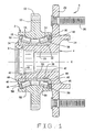
- Figure 1 is a longitudinal sectional view of a hub assembly having a spindle, the end of which is upset in accordance with the process of the invention to retain a bearing race on the spindle;
- Figure 2 is a fragmentary sectional view showing a deformable end on the spindle, which end is capable of being upset to capture a bearing race on the spindle;
- Figure 3 is an elevational view of a rotary forming machine used to upset the deformable end on the spindle of the hub assembly;
- Figures 4 A, B, C, D are fragmentary sectional views, in sequence, showing the deformable end on the spindle being converted into a formed end which captures the bearing race;
- Figure 5 is a graph representing one algorithm for monitoring the process for converting the deformable end on the spindle into a formed end; and
- Figure 6 is a graph representing another algorithm for monitoring the process.
- Corresponding reference characters indicate corresponding parts throughout the several views of the drawings.
- Referring now to the drawings, a hub assembly A (Fig. 1), during the procedure under which it is assembled, has one of its components deformed against another of its components to unitize the assembly (Fig. 4). The processes utilized in deforming may leave the upset component with excessive deformation or incomplete deformation, either of which will adversely affect the operation of the hub assembly A The process is monitored to ensure that the forces exerted at defined intervals, and the rates at which such forces increase or decrease meet certain criteria which will identify a proper deformation.
- With regard to the hub assembly A itself it includes (Fig., 1) a
housing 2, ahub 4, and abearing 6 that is located between thehousing 2 and thehub 4 to enable thehub 4 to rotate on thehousing 2 about an axis X with minimal friction. Thehousing 2 is configured to be attached securely to a suspension system component of an automotive vehicle, whereas thehub 4 is configured to accommodate a brake rotor or drum, and a road wheel. The bearing 6 transfers both radial loads and thrust loads in both axial directions between thehousing 2 and thehub 4. - The housing 2 (Fig. 1) on its exterior has a triangular or
rectangular flange 10 located generally midway between its ends, and threadedholes 12 in the lobes of theflange 10. Theflange 10 fits against a suspension system component, and theholes 12 receive machine screws which pass through the suspension system component and secure thehousing 2 firmly to that component. Within its interior, thehousing 2 has a pair oftapered raceways 14 which taper downwardly toward each other. At their large ends theraceways 14 open intocounterbores 16 which in turn open out of the ends of thehousing 2. Theraceways 14 actually form part of thebearing 6, and in a sense thehousing 2 constitutes the outer race of thebearing 6. - The
hub 4 includes aspindle 20 which extends into thehousing 2 and aflange 22 formed integral with thespindle 20 at the outboard end of thespindle 20. Thehub flange 22 extends radially outwardly just past theflange 10 on thehousing 2 and surrounds awheel pilot 24 which projects from beyond its outboard face. Theflange 22 carries several threadedstuds 26 which likewise project beyond its outboard face. A brake disk fits over the threadedstuds 26 and around thewheel pilot 24, as does a road wheel. Both are clamped tightly to theflange 22 by lug nuts which thread over thestuds 26. - On its opposite face, that is its inboard face, the
flange 22 has ashoulder 30 where the flange merges into thespindle 20. The outwardly presented surface of theshoulder 30 forms acylindrical bearing seat 32. At its inboard end, thespindle 20 turns outwardly away from thebearing seat 32 in the provision of a formedend 34. Thespindle 20 in the region of thebearing seat 32 may be hollow or solid, but at its formedend 34 it is hollow. - The bearing 6 fits around the
spindle 20 between theshoulder 30 and the formedend 34, and fits within thehousing 2. In addition to the twoouter raceways 14, thebearing 6 includes inner races in the form of anoutboard cone 38 and aninboard cone 40, each having abore 42, which extends completely through thebearing 6. Thebores 42 of the twocones spindle 20 of thehub 4, there being interference fits between thebearing seat 32 and bore 42. Thus, the twocones spindle 20 between theshoulder 30 and the formedend 34. Eachcone tapered raceway 44 that is presented outwardly away from the axis X, athrust rib 46 at the large end of itsraceway 44, and aback face 48 which is on the end of thethrust rib 46 where it is squared off with respect to the axis X. Thebore 42 opens out of theback face 48 at a radius. - The
inboard cone 40 is somewhat longer than theoutboard cone 38 by reason of acone extension 50 which projects beyond the small end of itsraceway 44 and may serve as a seat for a target wheel used to monitor the rotation of thehub 4. - The
raceway 44 of theoutboard cone 38 is presented toward theoutboard raceway 14 in thehousing 2 and tapers in the same direction, whereas theraceway 44 on theinboard cone 40 is presented toward theinboard raceway 14 of thehousing 4 and tapers in the same direction as that raceway. Thus, theoutboard raceways inboard races inboard cone 40, at itscone extension 50, abuts the small end of theoutboard cone 38 along the bearingseat 32. That is to say, the twocones back face 46 of theoutboard cone 38 abuts theshoulder 30 at theflange 22, while theback face 46 of theinboard cone 40 abuts the formedend 34 on thespindle 20. Thus, the twocones shoulder 30 and the formedend 34. - In addition to the
cones raceways 14 on thehousing 4, thebearing 6 includes taperedrollers 56 arranged in two rows, there being a separate row around eachcone rollers 56 extend around theraceways 44 for thecones raceways 44 and their large end faces against thethrust ribs 46. Therollers 56 of each row are essentially on apex, which means that the envelopes in which their tapered side faces lie have their apices located at a common point along the axis X. Each row ofrollers 56 has acage 58 to maintain the proper spacing between therollers 56 in that row. - The
counterbores 16 in thehousing 2 containseals 60 which fit around thethrust ribs 46 on thecones bearing 6. These barriers isolate therollers 56 and theraceways - The two
cones bearing 6 will operate with the proper setting, which is usually preload, but may also be end play. In preload, no internal clearances exist within thebearing 6, and therollers 56 of the two rows snugly contact theraceways raceways bores 42 of thecones seat 32 of thespindle 20, enables thehub 4 to rotate relative to thehousing 2 without any radial or axial free motion, thus assuring that the axis X remains stable. The formedend 34 must be located and otherwise configured to clamp the twocones raceways 44 and thrustribs 46 are distorted, for to do so could hasten failure of thebearing 6. - The formed
end 34 unitizes the hub assembly A and is produced only after the twocones seat 32 of thespindle 20 with therollers 56 around thecones housing 2 around therollers 56. Initially, thespindle 20 of thehub 4 extends from theshoulder 30 out to its inboard end at a diameter no greater than the diameter of the bearingseat 32. In this configuration thespindle 20 has a deformable end 70 (Fig. 2) which merges with the remainder of thespindle 20 at the end of the bearingseat 32. Thedeformable end 70 is defined by acylindrical exterior surface 72, a contouredinterior surface 74 that is about as long as theexterior surface 72, and anend surface 76 that extends between the exterior andinterior surfaces exterior surface 72 possesses the same diameter as the bearingseat 32 and merges into the bearingseat 32 without a discemable distinction between the two surfaces. Thus, theexterior surface 72 and the bearingseat 32 are flush The presence of theinterior surface 74 renders thedeformable end 70 hollow. Thatinterior surface 74 begins in the region where the bearingseat 32 ends and extends with a compound curvature out to theend surface 76. It possesses its least diameter at the proximal end of thedeformable end 70 and its greatest diameter where it merges into theend surface 76 at the distal end of thedeformable end 70. Its greatest inclination with respect to the axis X exists at its proximal end. Theend surface 76 connects the exterior andinterior surfaces interior surface 74. - The procedure for assembling the hub assembly A, of course, begins with the
spindle 20 of thehub 2 extended, that is to say, possessing thedeformable end 70. First, the outboard cone 38 (Fig. 1), with its complement ofrollers 56 around itsraceway 44 and itsseal 60 fitted over itsthrust rib 46, is pressed over the exterior surface 72 (Fig. 2) on thedeformable end 70 and then over the bearingseat 32 until itsback face 48 comes against theshoulder 30. Next, the housing 2 (Fig. 1) is advanced over thespindle 20 and theoutboard cone 38 as well. Thecounterbore 16 at the outboard end of thehousing 4 aligns with theoutboard seal 60 and, with continued advancement, thatseal 60 is forced into thecounterbore 16. Theoutboard raceway 14 in thehousing 2 seats against therollers 56 that surroundoutboard cone 38. Thereupon, theinboard cone 40, with its complement ofrollers 56 around it, is forced over the exterior surface 72 (Fig. 2) on thedeformable end 70 and advanced over the bearingseat 32 until its cone extension 50 (Fig. 1) abuts the end of theoutboard cone 38. During the final increment of advance, thehub 4 is rotated relative to thehousing 2, or vice versa, to ensure that therollers 56 in the two rows seat properly along theraceways thrust ribs 46 as well. At this juncture, theinboard seal 60 may be pressed into theinboard counterbore 16 of thehousing 2 and over thethrust rib 46 of theinboard cone 40. - Once the
inboard cone 40 is in place over thespindle 20, the deformable end 70 (Fig. 2) is upset and converted into the formed end 34 (Fig. 1) which captures the twocones spindle 20 of thehub 4. The twocones rollers 56 that are around them hold thehousing 2 around thehub spindle 20, preventing both radial and axial displacement, but leaving thehub 4 free to rotate relative to thehousing 2 about the axis X. - International application PCT/GB98/01823, filed 22 June 1998 and published 30 December 1998 under International Publication No. WO 98/58762, discloses a rotary forming process for upsetting a deformable end that captures two cones on a spindle to unitize a hub assembly. However, the hub assembly that is produced should undergo an inspection to insure that formed end does not distort the bearing, yet captures the bearing firmly enough to insure that it operates in preload.
- Basically, the process for converting the
deformable end 70 into the formedend 34 utilizes a rotary forming machine B (Fig. 3) including a table 80 which is powered to rotate about a vertical axis Y and has an upwardly openingsocket 82 configured to receive thepilot 24 on thehub 4 while supporting the entire hub assembly A on theflange 22 of thehub 4. The axis X of the hub assembly A aligns with the axis Y of the table 80, so that thespindle 20 and table 80 rotate in unison with their respective axes X and Y coinciding. The table 80 rotates opposite a formingtool 86 which in turn rotates about an axis Z that is oblique to, yet intersects, the axis Y of rotation for the table 80. The forming tool 86 (Fig. 4) has a contoured face 88 that is presented toward thedeformable end 70 on thespindle 20 for thehub 4 supported on the table 80. Either the table 80 or thespindle 86 is fitted in a way which enables it to be displaced parallel to the axes X and Y, the displacement being provided by a hydraulic ram 90 (Fig. 3) or other force-producing device that is monitored by aload cell 92. - The contoured face 88 (Fig. 4) possesses an annular configuration and is depressed within the
tool 86, it having a frustoconicalinner region 100 and anouter region 102 that leads out to aperipheral edge 104. The diameter of theedge 104 equals the greatest diameter of the formedend 34 that is imparted to thehub spindle 20, yet is considerably larger than the diameter of theexterior surface 72 on thedeformable end 70. Owing to the inclination of the axis Z for formingtool 86 with respect to the axis Y for the table 80 and with respect to the corresponding axis X of thehub spindle 20 on the table 80, one segment of the contoured face 88 for thetool 86 will be closer to thedeformable end 70 than the remainder of the contoured face 88 (Fig. 4A). Indeed, theend surface 76 on thedeformable end 70 is presented toward that segment. At that segment of the contouredface 96, theperipheral edge 104 aligns with the location on the back face 48 (Fig. 1) of theinboard cone 40 at which the periphery of the formedend 34 will locate after the deformable end 70 (Fig. 4D) on thehub spindle 20 is converted into the formedend 34. - To upset the
deformable end 70, the table 80 rotates thehub 4 of the hub assembly A opposite the formingtool 86. The incomplete hub assembly A rests on the table 80 with itsflange 22 against the table 80 and thedeformable end 70 of itsspindle 20 presented upwardly toward the formingtool 86. Then with the table 80 rotating, theram 90 is energized. It brings the table 80 - and of course the hub assembly A that is on the table 80 - and the formingtool 86 together. Theend surface 76 on thedeformable end 70 comes against the frustoconicalinner region 100 of the contoured face 88 on the tool 86 (Fig. 4B), whereupon theram 90 exerts more force. Thedeformable end 70 deflects outwardly on the contoured face 88 of thetool 86, itsend surface 76 moving over theinner region 100 of the contoured face 88 toward and into the arcuate outer region 102 (Fig. C). Thetool 86 turns thedeformable end 70 backwardly over the radius between thebore 42 and back face 48 of theinboard cone 40 and drives it against theback face 48, thus providing the formedend 34 with a flat face that serves as an abutment to retain theinboard cone 40 on thespindle 20. The exterior surface of the formedend 34 assumes the configuration of the arcuateouter region 102 and the adjoininginner region 100 of the contoured face 88 of the forming tool 86 (Fig. 4D). As theram 90 urges thedeformable end 70 of thespindle 20 and the forming tool 94 together, theload cell 92 monitors the force exerted by theram 90. - The conversion of the
deformable end 70 on thespindle 20 and the formedend 34 occurs in three stages or phases - or perhaps four - represented by different rates of feed for bringing thedeformable end 70 and the formingtool 86 together and varying forces exerted by theram 90 and monitored by theload cell 92. Those forces are best analyzed from a plot of force against time on Cartesian coordinates (Figs. 5 & 6). However, before formingtool 86 actually comes in contact with thedeformable end 70, the forming machine B preferably determines the location of theback face 48 of theinboard cone 40 along the axes X and Y. However, if the machine B does not actually measure the location of theback face 48 for theinboard cone 40, the machine B may rely on a statistical stackup determined at the setup of the incomplete hub assembly A on the machine B. - If one considers the conversion in terms of four phases, the first could be considered search phase. In this phase the
hub 4 and the forming tool 84 approach quite rapidly, (Fig. 4A), but since no resistance is encountered, the force exerted by theram 90 is minimal. A steep rise in the force occurs when theend surface 76 on thedeformable end 70 of thespindle 20 contacts theinner region 100 of the contoured face 88 in the tool 86 (Fig. 4B). This marks the onset of the second phase, and the machine B registers the location along the axes X and Y at which it occurs. Here theram 90 transforms to a course feed, which is slower than the search feed of the first phase. The force exerted by theram 90 during the course feed or second phase rises rapidly, but thereafter the rate of increase, when measured against time, diminishes. During the second phase the formingtool 86 moves the metal of theend portion 70 at a high rate of speed, and theend surface 76 moves outwardly over theinner region 100 of the contouredface 96 and into the outer region 102 (Fig. 4C). It then turns backwardly toward theback face 48 of theinboard cone 40 and essentially assumes the configuration of the formed end 34 (Fig. 4D), although with a gap between thatend 34 and theback face 48 of theinboard cone 40. The course feed or second phase ends after thetool 86 and table 80 are brought together a prescribed distance measured from the location that marked the onset of the second phase, and that leaves the tool 86 a prescribed distance from theback face 48 of theinboard cone 40. - At the transition between the second phase and the third phase, the
ram 90 converts to a fine feed, and the force exerted immediately drops. However, as theram 90 continues to bring thespindle 20 and the formingtool 86 together, albeit at a slower speed, the metal at the end of thespindle 20 continues to flow - indeed, toward theback face 48 of the inboard cone 40 (Fig. 4D). The force exerted, after experiencing the initial drop and a sharp subsequent rise of short duration, continues to increase at a moderate and generally uniform rate. However, as the metal of the formedend 34 forms up into its final configuration against theback face 48 of theinboard core 40, the rate of increase in force per unit of time increases, signifying that the formedend 34 has indeed come against theback face 48 of theinboard cone 40. The formingtool 86 andhub spindle 20 close upon each other for a prescribed distance so that at the end of the third phase the formingtool 86 is a prescribed distance from theback face 48 of theinboard cone 40. The end of the third phase is marked by an end of the closure of thespindle 20 upon the formingtool 86, yet without a separation of thespindle 20 from the formingtool 86. In short, the fourth phase represents a dwell in which thespindle 20 and formingtool 86 remained fixed in position, save for the rotation. During the fourth phase, the force exerted by theram 90 at first diminishes and then becomes nearly constant At this time the formedend 34 assumes its final configuration in which it bears snugly against theback face 48 of theinboard cone 40 and clamps the twocones bearing 6, which is usually in preload. - Too much or too little metal in the deformable end 70 - or more accurately in the portion of the
deformable end 70 that projects beyond theback face 48 of the inboard cone 40 - will cause the third and fourth phases, and most likely both, to deviate somewhat from that described, and the deviations serve to identify defective hub assemblies A which require rejection. For example, the failure of the third phase to produce a spike in the force near its end suggests that the formedend 34 has not made tight contact with theback face 48 of theinboard cone 40. In other words, the average rate of increase toward the end of the third phase must exceed a minimal value to insure that the formedend 34 is seated firmly against theback face 48 of theinboard cone 40. If the maximum force exerted at the end of the third phase fails to reach a prescribed minimum, that too will indicate that the formedend 34 has not fully seated. So will the absence of a generally uniform force during the fourth phase or dwell. Indeed, even a moderate decline in the force toward the end of the fourth phase suggests that the metal in the formedend 34 is still moving away from the formingtool 86. - On the other hand, if the force exerted at the end of the third phase exceeds a prescribed maximum, a good possibility exists that the
inboard cone 40 experienced some deformation at itsthrust rib 46. Exceeding a prescribed maximum in the fourth phase will also reflect excessive force at thethrust rib 46 of theinboard cone 38. - The evaluation of the force at progressive intervals lends itself to several algorithms for identifying hub assemblies A which should be rejected. This evaluation is best undertaken from a consideration of the plot of force against time for an acceptable hub assembly A (Figs. 5 & 6).
- One algorithm (Fig. 5) considers the following criteria from the comparison of force against time, and the failure to fall within the limits for any one of those criteria should result in a rejection of the hub assembly A:
- 1. The rate a of increase in force leading up to maximum force at the end of the third or fine feed phase. A spike at the final increment of the fine feed indicates that the formed
end 34 has made contact with theback face 48 of theinboard cone 40 and has thus encountered greater resistance to the flow of metal. In other words, the load curve must exhibit a moderate slope and then a steeper slope immediately before the end of the fine feed, with a deflection point p between the two slopes, and the steep slope must exceed a prescribed slope a. - 2. The peak force during the fine feed, which should be at the end of the third phase, must exceed a prescribed minimum b. This will verify that the formed
end 34 has seated against theface 48 of theinboard cone 40. - 3. The average rate of increase of force during the fine feed or third phase must exceed a prescribed minimum, with average being calculated as a moving average from equally spaced data points, perhaps five spaced 0.01 seconds apart. This ensures the presence of a force spike at the end of the fine feed, and provides an additional check on the closure of the gap between the formed
end 34 and the cone back face 48. - 4. The force during the dwell or fourth phase, after the initial decrease in that force, must remain relatively constant and above a prescribed minimum c. If the force continues to decrease during the dwell period or falls below the prescribed minimum c, the formed
end 34 may not have fully closed on the cone back face 48. - Another algorithm (Fig. 6) considers the following criteria in the comparison of force against time, and a violation of the limits set for any single criterium should result in a rejection of the hub assembly A:
- 1. The rate of increase in force approaching the end of the fine feed or third phase. This is determined by measuring the rate (slope) at equally spaced data points immediately prior to the force at the end of the fine feed and taking a moving average. An average rate (slope) that lies below a prescribed minimum rate e suggests the absence of closure between the formed
end 34 and the cone back face 48. - 2. The maximum force achieved during the fine feed or third phase. This force should exceed a prescribed minimum f which generally assures a closure of the formed
end 34 on the cone back face 48. Then, again it should lie below a prescribed maximum g which generally represents a force at which thethrust rib 46 of theinboard cone 40 will deform. In short, the maximum force during the fine feed should lie between prescribed maximum and minimum forces f and g, respectively. - 3. The change in the rate at which the force decreases approaching the end of the fourth or dwell phase. The rate cannot decrease too rapidly, for if it did, it would signify that the metal is still moving away from the forming
tool 86 during the dwell phase. In other words, the slope of the load curve near the end of the fourth phase must remain below a prescribed maximum h. - 4. The average force during the portion of the fourth or dwell phase that follows the initial decrease in the force after the entry into the fourth or dwell phase. This average force must remain above a prescribed minimum i to verify that the formed
end 34 has closed on the cone back face 48, yet must be below a prescribed maximum j. If the force exceeds the prescribed maximum i, it may distort the cone thrustrib 46. - The
load cell 92 produces an electrical signal which is directed to a microprocessor that further receives a time signal from a clock to provide the time base. The microprocessor recognizes the magnitude of the force registered at any instant by theload cell 92 and the time at which it occurs, in effect producing a load curve (Figs. 5 & 6). Maximum and minimum limits for force and slopes during the third and fourth phases are stored in the microprocessor. These limits may include maximum and minimum forces b, f, and g for the portion of the load curve leading to the transition between the third and fourth phases, maximum and minimum forces c, i, and j for the portion of the load curve approaching the end of the fourth phase, a minimum slope a and e for the portion of the slope leading up to the transition between the third and fourth phases; and a maximum slope h for the load curve where it approaches the end of the fourth phase. Finally, the microprocessor registers the initial position of theback face 48 for theinboard core 40 along the axes X and Y and ascertains the spacing between thatback face 48 and the position of the formingtool 86 at the outset of the second phase. It retains a prescribed distance for closure between theback face 48 and formingtool 86 for both the second and third phases and controls the closure so that the second and third phase experience the correct closure. - No two rotary forming machines B function the same, much less any two forming
tools 86. The maximum and minimum forces and slopes suited for one machine B andtool 86 generally do not apply to another machine B andtool 86. Thus, the level for the force and slope with each machine B andtool 86 must be established empirically. Through a series of calibrating runs and measurements made manually on the completed hub assemblies A produced in these runs, one can determine the magnitude of maximum and minimum forces and slopes beyond which unacceptable hub assemblies A result. - The outboard
inner race 38 may be formed integral with thespindle 20, in which event the outboardinner raceway 44 is on thespindle 20. Also, theoutboard raceway 14 may be on a separate double cup pressed into thehousing 2, or on two single cups likewise pressed into thehousing 4. Thebearing 6 need not be a tapered roller bearing, but instead an angular contact bearing or any other antifriction bearing capable of accommodating thrust loading. The formed end need not be directly against theback face 48 of theinboard cone 40, but instead may be against an intervening member such as a ring or flange that is captured between the formedend 34 and the cone back face 48. In that event, the end of the intervening member is considered the cone back face 48.
Claims (6)
- A process for upsetting a hollow deformable end (70) on a spindle (20) that projects through an inner race (40) of an antifriction bearing (6) with the inner race having a back face (48) beyond which the deformable end is located, said process comprising: rotating the spindle and a forming tool (86) located beyond the spindle; forcing the rotating forming tool (86) and the deformable end (70) of the spindle together; while the force is exerted and the spindle and tool are rotating, decreasing the distance between forming tool (86) and the inner race (40) in a feed phase so that the deformable end transforms into a formed end (34) that is directed outwardly and located opposite the back face (48) of the inner race; thereafter, while the force is applied, maintaining the distance between the forming tool (86) and the inner race (40) essentially constant in a dwell phase; monitoring the force at which the spindle (20) and the forming tool (86) are urged together in the feed phase; characterised in that the process further comprises monitoring the force at which the spindle and forming tool are urged together in the dwell phase; and determining if the force at prescribed intervals meets established criteria for rejection of the spindle (20) and antifriction bearing (6), which criteria includes exceeding a minimum force at the end of the feed phase immediately prior to the dwell phase.
- The process according to claim 1 wherein the criteria also includes exceeding a minimum rate of increase in the force immediately prior to the dwell phase.
- The process according to claim 1 or claim 2 wherein the criteria also includes remaining below a prescribed maximum force at the end of the feed phase.
- The process according to any one of claims 1 to 3 wherein the force decreases during the dwell phase, and the criteria further includes exceeding a prescribed rate of decrease approaching the end of the dwell phase.
- The process according to any one of claims 1 to 4 wherein the criteria also includes approaching the end of the dwell phase maintaining an average force that exceeds another prescribed minimum force.
- The process according to any one of claims 1 to 5 wherein the criteria also includes detecting an inflection point representing a change in the rate of force increase during the feed phase.
Applications Claiming Priority (3)
| Application Number | Priority Date | Filing Date | Title |
|---|---|---|---|
| US997603 | 1992-12-28 | ||
| US09/997,603 US6532666B1 (en) | 2001-11-29 | 2001-11-29 | Process for capturing a bearing race on a spindle |
| PCT/US2002/024231 WO2003048596A1 (en) | 2001-11-29 | 2002-07-30 | Process for capturing a bearing race on a spindle |
Publications (2)
| Publication Number | Publication Date |
|---|---|
| EP1448906A1 EP1448906A1 (en) | 2004-08-25 |
| EP1448906B1 true EP1448906B1 (en) | 2006-09-27 |
Family
ID=25544202
Family Applications (1)
| Application Number | Title | Priority Date | Filing Date |
|---|---|---|---|
| EP02756829A Expired - Lifetime EP1448906B1 (en) | 2001-11-29 | 2002-07-30 | Process for capturing a bearing race on a spindle |
Country Status (8)
| Country | Link |
|---|---|
| US (1) | US6532666B1 (en) |
| EP (1) | EP1448906B1 (en) |
| JP (1) | JP2005511981A (en) |
| KR (1) | KR100878328B1 (en) |
| CN (1) | CN1596346A (en) |
| AU (1) | AU2002322809A1 (en) |
| DE (1) | DE60215041T2 (en) |
| WO (1) | WO2003048596A1 (en) |
Families Citing this family (17)
| Publication number | Priority date | Publication date | Assignee | Title |
|---|---|---|---|---|
| JP2002225503A (en) * | 2000-11-29 | 2002-08-14 | Nsk Ltd | Method of producing hub unit for supporting wheel and pressing die for producing the same |
| ITTO20020653A1 (en) * | 2002-07-24 | 2004-01-26 | Skf Ind Spa | MONITORING OF THE HEAVY AXIAL LOAD ON THE WHEEL HUB OF A MOTOR VEHICLE |
| KR20050066265A (en) | 2003-12-26 | 2005-06-30 | 엘지전자 주식회사 | Method for managing and reproducing a menu information of high density optical disc |
| KR20050066264A (en) | 2003-12-26 | 2005-06-30 | 엘지전자 주식회사 | Method for managing and reproducing a menu information of high density optical disc |
| US7360951B2 (en) * | 2004-01-28 | 2008-04-22 | Visteon Global Technologies, Inc. | Detachable half shaft assembly of a vehicle wheel end |
| EP1717467B1 (en) * | 2004-02-18 | 2010-10-27 | NTN Corporation | Bearing device for wheel |
| US7677807B2 (en) * | 2004-03-03 | 2010-03-16 | Nsk Ltd. | Hub unit for wheel |
| US7117599B2 (en) * | 2004-10-28 | 2006-10-10 | Robert Bosch Gmbh | Method of manufacturing a corner assembly |
| US7159316B2 (en) * | 2004-10-28 | 2007-01-09 | Robert Bosch Gmbh | Method of manufacturing a modular corner assembly |
| US20060091719A1 (en) * | 2004-10-29 | 2006-05-04 | Robert Bosch Corporation | Wheel hub for a corner assembly |
| US20070116397A1 (en) * | 2005-11-18 | 2007-05-24 | The Timken Company | Unitized bearing assembly and method of assembling the same |
| WO2007073483A1 (en) | 2005-12-21 | 2007-06-28 | The Timken Company | Wheel end with coupler |
| WO2007103915A2 (en) * | 2006-03-06 | 2007-09-13 | The Timken Company | A load sensing wheel end |
| US8465211B2 (en) * | 2008-01-10 | 2013-06-18 | The Timken Company | Compact wheel end and corner module |
| DE102009023042A1 (en) * | 2009-05-28 | 2010-07-01 | Schaeffler Technologies Gmbh & Co. Kg | Method for stamping spur gearing from rolling riveting flange of wheel bearing on automobile sector, involves radially limiting radial expansion of flange by die plate during deformation of end piece and formation of spur gearing |
| CN116691226A (en) * | 2015-11-02 | 2023-09-05 | 舍弗勒技术股份两合公司 | wheel bearing unit |
| US11820171B2 (en) * | 2021-01-07 | 2023-11-21 | Arvinmeritor Technology, Llc | Axle assembly having a drive pinion and a preload nut and a method of assembly |
Family Cites Families (13)
| Publication number | Priority date | Publication date | Assignee | Title |
|---|---|---|---|---|
| DE3636243A1 (en) | 1986-10-24 | 1988-05-11 | Loehr & Bromkamp Gmbh | WHEEL BEARING (NY) SMOOTH JOINT UNIT |
| DE3920299A1 (en) | 1989-06-21 | 1991-01-03 | Kugelfischer G Schaefer & Co | WHEEL BEARING FOR MOTOR VEHICLES |
| FR2666389B1 (en) | 1990-09-04 | 1992-10-23 | Roulements Soc Nouvelle | PROCESS FOR PRODUCING A BEARING COLLAR AND BEARING ASSEMBLY EQUIPPED WITH SUCH A COLLAR. |
| DE4134434C2 (en) | 1991-10-18 | 1993-12-02 | Kugelfischer G Schaefer & Co | Wheel bearing unit with a speed determination device |
| DE4335793C2 (en) | 1993-10-20 | 1998-04-09 | Kugelfischer G Schaefer & Co | Method and device for assembling a bearing unit, preferably a wheel bearing unit for motor vehicles |
| DE4339847C2 (en) | 1993-11-23 | 2000-09-14 | Kugelfischer G Schaefer & Co | Storage unit |
| DE19613441B4 (en) * | 1996-04-04 | 2005-03-24 | Fag Kugelfischer Ag | Method for producing a multi-part bearing assembly |
| US5822859A (en) * | 1996-10-07 | 1998-10-20 | General Motors Corporation | Bearing with integrally retained separable race |
| AU6012398A (en) | 1996-12-10 | 1998-07-03 | Kelsey-Hayes Company | Vehicle wheel hub and bearing retention system and method for producing same |
| GB9713343D0 (en) | 1997-06-24 | 1997-08-27 | Timken Co | Process and machine for uniting rotatable machine components |
| DE69932782T2 (en) * | 1998-09-11 | 2007-12-27 | Jtekt Corp., Osaka | bearing device |
| JP3930675B2 (en) | 2000-02-17 | 2007-06-13 | Ntn株式会社 | Wheel bearing device and bearing clearance management method thereof |
| US6491440B1 (en) * | 1999-09-22 | 2002-12-10 | Ntn Corporation | Wheel bearing apparatus |
-
2001
- 2001-11-29 US US09/997,603 patent/US6532666B1/en not_active Expired - Lifetime
-
2002
- 2002-07-30 AU AU2002322809A patent/AU2002322809A1/en not_active Abandoned
- 2002-07-30 WO PCT/US2002/024231 patent/WO2003048596A1/en active IP Right Grant
- 2002-07-30 JP JP2003549753A patent/JP2005511981A/en active Pending
- 2002-07-30 KR KR1020047008382A patent/KR100878328B1/en active IP Right Grant
- 2002-07-30 EP EP02756829A patent/EP1448906B1/en not_active Expired - Lifetime
- 2002-07-30 DE DE60215041T patent/DE60215041T2/en not_active Expired - Lifetime
- 2002-07-30 CN CNA028238389A patent/CN1596346A/en active Pending
Also Published As
| Publication number | Publication date |
|---|---|
| US6532666B1 (en) | 2003-03-18 |
| KR20040079903A (en) | 2004-09-16 |
| CN1596346A (en) | 2005-03-16 |
| EP1448906A1 (en) | 2004-08-25 |
| DE60215041T2 (en) | 2007-07-12 |
| KR100878328B1 (en) | 2009-01-14 |
| WO2003048596A1 (en) | 2003-06-12 |
| AU2002322809A1 (en) | 2003-06-17 |
| DE60215041D1 (en) | 2006-11-09 |
| JP2005511981A (en) | 2005-04-28 |
Similar Documents
| Publication | Publication Date | Title |
|---|---|---|
| EP1448906B1 (en) | Process for capturing a bearing race on a spindle | |
| US5494358A (en) | Package bearing | |
| JP3582730B2 (en) | Method and machine for integrating rotatable machine components | |
| EP1200219B1 (en) | Process for producing a hub assembly having minimum runout | |
| US5386630A (en) | Process and tool for adjusting bearings | |
| US20070116397A1 (en) | Unitized bearing assembly and method of assembling the same | |
| EP0521693B1 (en) | Bearing assembly with speed sensor and process for assembling the same | |
| EP1962074A1 (en) | Sensor-equipped bearing for wheel | |
| US5937499A (en) | Machining brake disc without moment load on bearing | |
| US20020118899A1 (en) | Wheel bearing device | |
| US6640438B2 (en) | Process and machine for uniting rotatable machine components | |
| US5915502A (en) | Brake disc assembly and a method for fabricating brake disc | |
| JP6551634B1 (en) | Hub unit bearing manufacturing method and manufacturing apparatus, vehicle manufacturing method | |
| WO2011019703A1 (en) | Method and apparatus for bearing race creep prevention |
Legal Events
| Date | Code | Title | Description |
|---|---|---|---|
| PUAI | Public reference made under article 153(3) epc to a published international application that has entered the european phase |
Free format text: ORIGINAL CODE: 0009012 |
|
| 17P | Request for examination filed |
Effective date: 20040602 |
|
| AK | Designated contracting states |
Kind code of ref document: A1 Designated state(s): AT BE BG CH CY CZ DE DK EE ES FI FR GB GR IE IT LI LU MC NL PT SE SK TR |
|
| AX | Request for extension of the european patent |
Extension state: AL LT LV MK RO SI |
|
| GRAP | Despatch of communication of intention to grant a patent |
Free format text: ORIGINAL CODE: EPIDOSNIGR1 |
|
| GRAS | Grant fee paid |
Free format text: ORIGINAL CODE: EPIDOSNIGR3 |
|
| GRAA | (expected) grant |
Free format text: ORIGINAL CODE: 0009210 |
|
| AK | Designated contracting states |
Kind code of ref document: B1 Designated state(s): DE FR GB SE |
|
| REG | Reference to a national code |
Ref country code: GB Ref legal event code: FG4D |
|
| REF | Corresponds to: |
Ref document number: 60215041 Country of ref document: DE Date of ref document: 20061109 Kind code of ref document: P |
|
| REG | Reference to a national code |
Ref country code: SE Ref legal event code: TRGR |
|
| ET | Fr: translation filed | ||
| PGFP | Annual fee paid to national office [announced via postgrant information from national office to epo] |
Ref country code: SE Payment date: 20070615 Year of fee payment: 6 |
|
| PLBE | No opposition filed within time limit |
Free format text: ORIGINAL CODE: 0009261 |
|
| STAA | Information on the status of an ep patent application or granted ep patent |
Free format text: STATUS: NO OPPOSITION FILED WITHIN TIME LIMIT |
|
| 26N | No opposition filed |
Effective date: 20070628 |
|
| EUG | Se: european patent has lapsed | ||
| PG25 | Lapsed in a contracting state [announced via postgrant information from national office to epo] |
Ref country code: SE Free format text: LAPSE BECAUSE OF NON-PAYMENT OF DUE FEES Effective date: 20080731 |
|
| REG | Reference to a national code |
Ref country code: FR Ref legal event code: PLFP Year of fee payment: 15 |
|
| REG | Reference to a national code |
Ref country code: FR Ref legal event code: PLFP Year of fee payment: 16 |
|
| REG | Reference to a national code |
Ref country code: FR Ref legal event code: PLFP Year of fee payment: 17 |
|
| PGFP | Annual fee paid to national office [announced via postgrant information from national office to epo] |
Ref country code: FR Payment date: 20210727 Year of fee payment: 20 |
|
| PGFP | Annual fee paid to national office [announced via postgrant information from national office to epo] |
Ref country code: GB Payment date: 20210721 Year of fee payment: 20 Ref country code: DE Payment date: 20210721 Year of fee payment: 20 |
|
| REG | Reference to a national code |
Ref country code: DE Ref legal event code: R071 Ref document number: 60215041 Country of ref document: DE |
|
| REG | Reference to a national code |
Ref country code: GB Ref legal event code: PE20 Expiry date: 20220729 |
|
| PG25 | Lapsed in a contracting state [announced via postgrant information from national office to epo] |
Ref country code: GB Free format text: LAPSE BECAUSE OF EXPIRATION OF PROTECTION Effective date: 20220729 |