EP1178869B1 - Method of and apparatus for removing material - Google Patents
Method of and apparatus for removing material Download PDFInfo
- Publication number
- EP1178869B1 EP1178869B1 EP00935277A EP00935277A EP1178869B1 EP 1178869 B1 EP1178869 B1 EP 1178869B1 EP 00935277 A EP00935277 A EP 00935277A EP 00935277 A EP00935277 A EP 00935277A EP 1178869 B1 EP1178869 B1 EP 1178869B1
- Authority
- EP
- European Patent Office
- Prior art keywords
- wheel
- workpiece
- cutting
- axis
- detected
- Prior art date
- Legal status (The legal status is an assumption and is not a legal conclusion. Google has not performed a legal analysis and makes no representation as to the accuracy of the status listed.)
- Expired - Lifetime
Links
Images


Classifications
-
- B—PERFORMING OPERATIONS; TRANSPORTING
- B23—MACHINE TOOLS; METAL-WORKING NOT OTHERWISE PROVIDED FOR
- B23D—PLANING; SLOTTING; SHEARING; BROACHING; SAWING; FILING; SCRAPING; LIKE OPERATIONS FOR WORKING METAL BY REMOVING MATERIAL, NOT OTHERWISE PROVIDED FOR
- B23D59/00—Accessories specially designed for sawing machines or sawing devices
- B23D59/001—Measuring or control devices, e.g. for automatic control of work feed pressure on band saw blade
-
- B—PERFORMING OPERATIONS; TRANSPORTING
- B24—GRINDING; POLISHING
- B24B—MACHINES, DEVICES, OR PROCESSES FOR GRINDING OR POLISHING; DRESSING OR CONDITIONING OF ABRADING SURFACES; FEEDING OF GRINDING, POLISHING, OR LAPPING AGENTS
- B24B27/00—Other grinding machines or devices
- B24B27/06—Grinders for cutting-off
-
- B—PERFORMING OPERATIONS; TRANSPORTING
- B24—GRINDING; POLISHING
- B24B—MACHINES, DEVICES, OR PROCESSES FOR GRINDING OR POLISHING; DRESSING OR CONDITIONING OF ABRADING SURFACES; FEEDING OF GRINDING, POLISHING, OR LAPPING AGENTS
- B24B47/00—Drives or gearings; Equipment therefor
- B24B47/22—Equipment for exact control of the position of the grinding tool or work at the start of the grinding operation
-
- B—PERFORMING OPERATIONS; TRANSPORTING
- B24—GRINDING; POLISHING
- B24B—MACHINES, DEVICES, OR PROCESSES FOR GRINDING OR POLISHING; DRESSING OR CONDITIONING OF ABRADING SURFACES; FEEDING OF GRINDING, POLISHING, OR LAPPING AGENTS
- B24B49/00—Measuring or gauging equipment for controlling the feed movement of the grinding tool or work; Arrangements of indicating or measuring equipment, e.g. for indicating the start of the grinding operation
- B24B49/16—Measuring or gauging equipment for controlling the feed movement of the grinding tool or work; Arrangements of indicating or measuring equipment, e.g. for indicating the start of the grinding operation taking regard of the load
-
- B—PERFORMING OPERATIONS; TRANSPORTING
- B24—GRINDING; POLISHING
- B24B—MACHINES, DEVICES, OR PROCESSES FOR GRINDING OR POLISHING; DRESSING OR CONDITIONING OF ABRADING SURFACES; FEEDING OF GRINDING, POLISHING, OR LAPPING AGENTS
- B24B49/00—Measuring or gauging equipment for controlling the feed movement of the grinding tool or work; Arrangements of indicating or measuring equipment, e.g. for indicating the start of the grinding operation
- B24B49/18—Measuring or gauging equipment for controlling the feed movement of the grinding tool or work; Arrangements of indicating or measuring equipment, e.g. for indicating the start of the grinding operation taking regard of the presence of dressing tools
- B24B49/183—Wear compensation without the presence of dressing tools
-
- B—PERFORMING OPERATIONS; TRANSPORTING
- B28—WORKING CEMENT, CLAY, OR STONE
- B28D—WORKING STONE OR STONE-LIKE MATERIALS
- B28D7/00—Accessories specially adapted for use with machines or devices of the preceding groups
- B28D7/005—Devices for the automatic drive or the program control of the machines
-
- G—PHYSICS
- G05—CONTROLLING; REGULATING
- G05B—CONTROL OR REGULATING SYSTEMS IN GENERAL; FUNCTIONAL ELEMENTS OF SUCH SYSTEMS; MONITORING OR TESTING ARRANGEMENTS FOR SUCH SYSTEMS OR ELEMENTS
- G05B19/00—Programme-control systems
- G05B19/02—Programme-control systems electric
- G05B19/18—Numerical control [NC], i.e. automatically operating machines, in particular machine tools, e.g. in a manufacturing environment, so as to execute positioning, movement or co-ordinated operations by means of programme data in numerical form
- G05B19/416—Numerical control [NC], i.e. automatically operating machines, in particular machine tools, e.g. in a manufacturing environment, so as to execute positioning, movement or co-ordinated operations by means of programme data in numerical form characterised by control of velocity, acceleration or deceleration
- G05B19/4166—Controlling feed or in-feed
-
- G—PHYSICS
- G05—CONTROLLING; REGULATING
- G05B—CONTROL OR REGULATING SYSTEMS IN GENERAL; FUNCTIONAL ELEMENTS OF SUCH SYSTEMS; MONITORING OR TESTING ARRANGEMENTS FOR SUCH SYSTEMS OR ELEMENTS
- G05B2219/00—Program-control systems
- G05B2219/30—Nc systems
- G05B2219/49—Nc machine tool, till multiple
- G05B2219/49072—Action, withdraw, stop feed tool to prevent breakage or lower load
Definitions
- the present invention relates to a method of and apparatus for removing material from, for example, a workpiece.
- the present invention relates to a method and apparatus for sectioning a workpiece in which a rotating abrasive wheel sections the workpiece by making a cut of progressively increasing depth in the workpiece.
- the present invention also relates to apparatus for, and a method of, positioning a tool in preparation for the removal of material from a workpiece.
- wheel as used herein is to be construed broadly to include any body of rotation. Thus, the term ranges from a thin abrasive cutting or sectioning saw to a tool of significant axial length which may have a profiled periphery.
- US 4,075,792 describes a rotary machine tool, such as a grinding wheel, mounted on a movable support serving to advance the tool toward a workpiece.
- the tool is driven by an electric motor whose operating current is measured by a sensor controlling the fluid supply to a hydraulic servomotor which is linked with the support.
- the advance is too rapid, the resulting rise in load resistance increases the operating current and causes a throttling of the fluid pressure, the rate of advance being thus optimized in conformity with the shape and/or composition of the workpiece.
- Abrasive cutting wheels are generally formed from sharp abrasive particles held in a resin. As the cutting edge of a fresh wheel is abraded, the resin is worn away to expose the sharp edges of the abrasive particles at the cutting edge. These sharp edges in time become blunted. However, with a sufficient shear force per unit area applied thereto by the workpiece during sectioning, the blunted abrasive particles will eventually be forced out from their positions in the wheel to allow the diameter of the wheel to be reduced so that further sharp abrasive particles are exposed at the cutting edge.
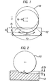
- Figure 1 illustrates a typical cutting action, in which a rotating abrasive wheel sections a workpiece in a single "feed", or motion of the axis of the wheel towards the workpiece.
- heat is generated, which propagates into the workpiece.
- the amount of heat which propagates into the workpiece is dependent, inter alia, on the ability of the blade to remove cutting material, or "dross", from the workpiece.
- the shear force F1 per unit area of wheel in contact with the workpiece decreases as the contact arc a of the wheel 10 increases; as the depth of the cut increases from d 1 to d 2 , the contact arc increases from a 1 to a 2 .
- This decrease in the shear force F1 can give rise to a situation where the shear force F2 per unit area of wheel 10 required to remove blunt abrasive particles from the cutting edge (in order to expose fresh abrasive particles at the cutting edge) is not reached. This has the effect of blunting the wheel.
- blunting of the wheel One problem associated with blunting of the wheel is that the blunt abrasive particles may rub and burnish the workpiece rather than cutting it. This reduces the ability of the blade to remove material from the workpiece, which can cause excessive heat to be generated in the workpiece, resulting in overheating, or "burning", of the workpiece. This can lead to problems when the cutting is performed to section a part from a workpiece (for example, a gear tooth from a gear wheel) for microstructural analysis, as excessive heat generating during sectioning can "heat treat" the workpiece, with the result that the microstructure of the sectioned part of the workpiece may be altered during sectioning.
- a workpiece for example, a gear tooth from a gear wheel
- This problem may be ameliorated to some extent by using a pulse action where the feed is interrupted whist the wheel is in contact with the workpiece and then fully reinstated.
- a pulsing action is intended to produce a momentarily high shear force F1, thereby replacing any blunted abrasive particles at the cutting edge with fresh abrasive particles.
- F2 is not greatly exceeded; it has been found that such pulse action sectioning can reduce wheel life by as much as one half.
- sectioning may be performed by making a series of cuts of progressively increasing depth in the workpiece.
- Such a sectioning action is illustrated in Figure 2.
- the sectioning action has two sequentially repeated actions, (i) an incremental feed of depth d of the wheel 10, and (ii) a traverse of the workpiece 12 to produce the cut.
- this sectioning action cutting is suspended whilst the incremental feed takes place, resulting in increased sectioning time. If constant feed is introduced, a uniform contact arc a cannot be maintained, which may result in blunting of the wheel.
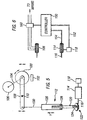
- FIG 3 Another problem associated with the sectioning action described with reference to Figure 2 is illustrated in Figure 3.
- the depth of the cut 14 increases from a depth d 1 as shown in Figure 3(a) to a depth d 2 as shown in Figure 3(b)
- internal stresses within the workpiece can cause the workpiece to bend or otherwise deform.
- This has the effect of narrowing the width w of the cut at the top of the workpiece from w 1 to w 2 .
- Such a reduction in the width w of the cut can cause the cut faces of the workpiece to grip the wheel as the cut progresses, exerting a pressure on the cutting motor and potentially stalling or breaking the cutting wheel.
- the cutting apparatus is typically programmable in order to enable an operator to programme the apparatus to make a sequence of spaced cuts in the workpiece.
- the workpiece may be clamped by a clamping mechanism which is traversable relative to the cutting wheel, for example, perpendicular to the cutting edge of the wheel, in order to alter the cutting position of the wheel on the workpiece.
- the operator can programme a sequence of (i) cutting of the workpiece by the wheel, followed by (ii) movement of the clamping mechanism relative to the wheel, in order, for example, to produce slices of equal thickness for the preparation of test specimens.
- the operator during programming of the sequence of cuts, the operator typically inputs a start position X1 for the centre of the cutting wheel 10, a finish position X2 for the centre of the cutting wheel 10 and a feed rate. These positions are chosen so that the cutting edge of the wheel does not touch the workpiece 12 with the wheel centre at position X1, but with the distance x between the cutting edge of the wheel and the workpiece as small as possible in order to reduce cutting time, and so that the sectioning will have been completed with the wheel centre at position X2 .
- the reduction in the diameter of the wheel may become so severe that towards the end of the cutting sequence sectioning of the workpiece may not have been completed by the time the time finish position X2 has been reached.
- the present invention provides apparatus for removing material from a workpiece, said apparatus being characterised by comprising:
- an abrasive surface of the wheel is moved with a rotational action to remove material from the workpiece.
- the energy required to maintain a constant rotational action is dependent upon a number of variables, including the speed of the action, the rate of advancement of the wheel towards the workpiece and the hardness and shape of the workpiece.
- the means for moving the abrasive surface with this action may not be able to maintain the speed of the action, resulting in a reduction of the speed of the action and potential blunting of the wheel, which can lead to burning of the workpiece.
- the present invention can avoid such burning of the workpiece by detecting the magnitude of the load applied to the wheel and, if the load rises above a predetermined level, adjusting the rate of the advancing movement between the wheel and the workpiece.
- the speed of the rotational action of the abrasive surface can be maintained at a high enough level to avoid blunting of the abrasive surface, thereby avoiding burning of the workpiece.
- the detecting means comprises means for monitoring a current drawn to move an abrasive surface of the wheel relative to the workpiece.
- the rotational action of the abrasive surface is driven by a motor, for example, a three phase motor drawing current directly from the mains power supply, which draws current sufficient to maintain a constant action of the abrasive surface. If a load is applied to the abrasive surface by the workpiece, the motor must draw more current in order to maintain the constant action of the abrasive surface.
- monitoring of the current drawn by the motor provides a convenient technique for monitoring the load on the abrasive surface.
- control means may be arranged to reduce the rate of the advancing movement when the current is greater than a predetermined value.
- control means may be arranged to reverse the advancing movement when the current drawn by the moving means is greater than a predetermined value for a predetermined period of time. This can enable grabbing of the wheel by the workpiece to be easily detected when the wheel is repeatedly (i) fed towards the workpiece and (ii) moved across the workpiece to produce a cut of sequentially increasing depth, as grabbing of the wheel by the workpiece can cause a load to be applied to the wheel even when the abrasive surface is not in contact with the workpiece.
- Grabbing ofthe wheel may be associated with a substantially constant load being applied to the wheel for a period of time.
- the control means may be arranged to reverse the advancing movement when the detected load is substantially constant for a predetermined period of time.
- the control means may be arranged to subsequently re-effect the advancing movement when the detected load falls below a predetermined value. This can enable the wheel to remove further material from the surfaces of the workpiece previously grabbing the wheel, thus relieving the load applied to the wheel during cutting.
- the control means may comprise means for monitoring the magnitude of the detected load during the removal of material at each of a plurality of spaced positions along the workpiece.
- the monitoring means may also be arranged to monitor the position of the wheel. This can provide accurate monitoring of the condition of the wheel during, for example, pre-programmed cutting of a series of sections from the workpiece.
- control means is arranged to control the positioning of the wheel in preparation for the removal of material from one of said spaced positions in response to wear of the wheel during the previous removal of material from at least two of said spaced positions.
- the monitoring means is arranged to detect the extent of the wear of the wheel from the relative positions of the wheel when contact is first made with the workpiece during said previous removal of material from at least two of said spaced positions. In another embodiment, the monitoring means is arranged to detect the extent of the wear of the wheel from the relative positions of the wheel when load applied to the wheel is first detected during said previous removal of material.
- the monitoring means can determine the wear of the wheel whilst removing material at, for example, the first of the spaced positions.
- the control means can then determine the approximate wear of the wheel whilst removing material at the second of the spaced positions.
- the control means can then calculate a position at which the wheel will begin to remove material at a third of the spaced positions. After the removal of material at the second of the spaced positions, the wheel can be rapidly moved to a position just before this calculated position.
- This process of using data gathered during two previous cuts, for example, can be repeated until all of the pre-programmed cuts have been made in the workpiece. This can provide for a significant decrease in the time taken to perform the series of cuts.
- the apparatus comprises means for detecting the load on the tool during the removal of material from said spaced positions along the workpiece, said control means being arranged to control the position of the tool in preparation for the removal of material from one of said spaced positions in response to wear of the tool as determined from the relative positions of the tool when load applied to the tool is first detected during said previous removal of material.
- the apparatus comprises an abrasive wheel having an abrasive circumferential surface and rotatable about a first axis passing through the centre thereof, and mounted to orbit about a second axis spaced from the first axis.
- abrasive wheel having an abrasive circumferential surface and rotatable about a first axis passing through the centre thereof, and mounted to orbit about a second axis spaced from the first axis.
- the advancing movement may be reversed if the current drawn by the moving means is greater than a predetermined value for at least one third of the time taken for the wheel to perform a full orbit of the second axis.
- the present invention extends to a method of removing material from a workpiece, said method being characterised by comprising the steps of:
- the apparatus comprises an abrasive tool in the form of rotatable abrasive wheel 100 having an abrasive circumferential edge for removing material from the workpiece 102.
- the present invention is not limited to such an abrasive tool.
- the tool may comprise a rotatable wheel having an abrasive face, or a reciprocating saw having a cutting edge.
- the workpiece 102 is gripped by a vice (not shown).
- the vice In order to enable a series of spaced cuts to be made along the workpiece 102, the vice is movable relative to the cutting wheel. Movement of the vice relative to the workpiece may be effected by any suitable mechanism, and may be either manual or automatically controlled by control apparatus in response to commands input from the operator.
- the wheel 100 is connected to a drive shaft 104 which is rotated by means of a cutting motor 106.
- the cutting motor 106 is preferably a three phase motor which draws current directly from the mains supply to rotate the drive shaft 104 at a constant rotational speed, although any other suitable motor may be used.
- the drive shaft 104 is rotatably mounted at one end of arm 108.
- the arm 108 is pivoted at 110.
- An actuator 112 for advancing the wheel 100 towards the workpiece 102 is connected to the other end of the arm 108.
- the actuator 112 can take any suitable form.
- the actuator 112 comprises an actuator motor 114 which rotates a first actuator drive shaft 116.
- An encoder 118 is coupled to the actuator motor 114 for rotation by the actuator motor 114 at the same rotational speed and direction as the first actuator drive shaft 116.
- the first actuator draft shaft 116 is coupled to a second actuator drive shaft 120 via gearing arrangement 122 for rotation about an axis substantially perpendicular to the rotational axis of the first actuator drive shaft.
- the second actuator drive shaft 120 is in the form of a lead screw 124.
- a nut 128 is mounted on the lead screw 124.
- the nut 128 has an internally threaded bore which engages the external thread of the lead screw 124.
- the nut 128 is attached to a tube 126 which is in turn connected to the other end of the arm 108 by linkage 130 which prevents the piston from rotating.
- the nut 128 can be moved axially relative to the lead screw 124 by rotation of the first actuator drive shaft 116 by the actuator motor 114.
- the wheel 100 is rotated by the cutting motor 106 at a constant rotational speed and the first actuator drive shaft 116 is rotated by the actuator motor 114 to move the piston in the direction Y as shown in Figure 5.
- This causes the arm to pivot about pivot 110 to move the wheel 100 towards the workpiece 102 in order to abrasively remove material from the workpiece.
- the rotation of the first actuator drive shaft 116 is reversed by the actuator motor 114, thus reversing the direction of motion of the pivot to move the wheel 100 away from the workpiece.
- FIG. 6 illustrates the arrangement of the control circuit for the cutting apparatus.
- the control circuit includes a controller 150, which in this preferred embodiment is provided by a programmable computer into which the operator inputs, inter alia:
- the operator selects these parameters depending on the hardness of the workpiece and the cross-sectional area and dimensions of the workpiece.
- the controller 150 is connected to the encoder 118 via electrical linkage 152.
- the controller monitors the speed and direction of the encoder 118 in order to obtain information concerning the rotational speed and direction of the first actuator drive shaft 116. This enables the controller 150 to monitor the position of the wheel 100, and speed and direction of movement of the wheel 100 towards the workpiece 102.
- the controller 150 is connected to the actuator motor 114 via electrical linkage 154.
- the controller In addition to monitoring and controlling the position and movement of the wheel 100 relative to the workpiece 102, the controller also monitors the magnitude of the load applied to the wheel by the workpiece by monitoring the size of the current drawn by the cutting motor 106 from the mains power supply. As illustrated in Figure 6, the controller 150 is connected to a transformer 160 which outputs to the controller 150 a signal of magnitude dependent on the size of the current drawn by the cutting motor 106 from the mains power supply.
- the cutting motor may become "overloaded", that is, the motor may not be able to overcome the retarding effect of the applied load by drawing further current from the mains supply.
- the cutting motor 106 will not be able to maintain the constant rotational speed of the wheel, resulting in a reduction in the rate of the rotation of the wheel (or even stalling of the blade). This reduction in the rate of rotation of the wheel reduces the shear force applied to the wheel by the workpiece, which can lead to non-removal of blunt abrasive particles at the cutting edge of the wheel.
- blunting of the wheel is that the blunt abrasive particles may rub and burnish the workpiece rather than cutting it. This reduces the ability of the blade to remove material from the workpiece, which can cause burning of the workpiece.
- overload limit In order to avoid overloading of the wheel, and thus any problems associated with burning of the workpiece, a limit of the amount of current to be drawn by the cutting motor, referred to as an "overload limit", is set by the operator of the apparatus.
- the overload limit is typically set according to the size of the cutting motor and the properties (size, composition, hardness, etc.) of the workpiece 102.
- the controller 150 controls the actuator motor 114 of the actuator 112 to reduce the rate of rotation of the first actuator shaft 116, and thus the rate of feed ⁇ 1 of the wheel 100 towards the workpiece 102.
- This has the effect of reducing the load applied to the wheel 100 by the workpiece 102 and thus, as illustrated in Figure 7, the amount of current required to be drawn by the cutting motor 106 from the mains power supply in order to maintain the constant rotational speed of the wheel. If following the decrease in the feed rate ⁇ 1 of the wheel the overload limit is reached again, the feed rate ⁇ 1 is decreased further. Thus, burning of the workpiece by the wheel can be substantially prevented.
- Cutting continues in this manner until the end position X2 of the wheel is reached, at which point the controller 150 controls the actuator motor 114 to withdraw the wheel from the workpiece, typically at a fixed speed ⁇ 2 greater than ⁇ 1 , to start position X1 .
- the vice can then be moved in order to re-position the workpiece 102 to enable a second cut to be made in the workpiece.
- the reduction in the diameter of the cutting wheel can lead to an effective increase in the cutting time. This is because the distance x between the edge of the cutting wheel 100 and the workpiece 102 when the wheel is at start position X1 increases as the series of cuts progresses. Thus, the wheel is moved an increasing distance at the relatively slow feed rate ⁇ 1 before contacting the workpiece 102.
- the controller 150 modifies the rate of advancement of the wheel towards the workpiece in response to wear of the wheel in order to reduce, for a number of the series of cuts, the time taken for the wheel to move the distance x . This is described in more detail below in an example in which four spaced cuts are made in a workpiece 102.
- the rotating wheel is first advanced by the actuator 112 at feed rate ⁇ 2 to start position X1. From start position X1, the rotating wheel is advanced towards the workpiece 102 at feed rate ⁇ 1 to cut the workpiece.
- the controller 150 monitors the current drawn by the cutting motor 106 and stores the position of the wheel, as determined from the information received from the encoder 118, at which the current drawn by the cutting motor first increases. Thus, the position X3 at which the wheel first contacts the workpiece 102 during the first cut is stored by the controller 150. Cutting continues as described above until end position X2 is reached by the wheel.
- the wheel is withdrawn from the workpiece at rate ⁇ 2 to start position X1 and the vice moved to position the workpiece for the second cut.
- the second cut proceeds in a similar manner to the first cut.
- the rotating wheel is advanced towards the workpiece 102 at feed rate ⁇ 1 to cut the workpiece.
- the controller 150 monitors the current drawn by the cutting motor 106 and stores the position of the wheel, as determined from the information received from the encoder 118, at which the current drawn by the cutting motor first increases.
- the position X3' at which the wheel first contacts the workpiece 102 during the second cut is stored by the controller 150. Cutting continues as described above until end position X2 is reached by the wheel.
- the controller Prior to withdrawal of the wheel from the workpiece, the controller compares positions X3 and X3'. For a workpiece of known profile, any difference between these two positions will be due to wear of the cutting wheel during the first cut, resulting in a reduction of the diameter of the wheel. From the difference between X3 and X3', the controller determines the amount of wear of the wheel during the first cut. Assuming that the wear of the wheel during the second cut will be approximately the same as the amount of the wear of the wheel during the first cut, the controller determines a position X3" art at which the wheel will first contact the workpiece during the third cut.
- the wheel is then withdrawn from the workpiece at rate ⁇ 2 to a position X1' just before X3" art (so that there is no contact between the wheel and the workpiece whilst the workpiece is moved to the third cutting position) and the vice moved to position the workpiece for the third cut.
- the wheel may be moved directly to position X3" art .
- the rotating wheel is advanced towards the workpiece 102 at feed rate ⁇ 1 to cut the workpiece.
- the controller 150 again monitors the current drawn by the cutting motor 106 and stores the position of the wheel, as determined from the information received from the encoder 118, at which the current drawn by the cutting motor first increases.
- the actual position X3" at which the wheel first contacts the workpiece 102 during the third cut is stored by the controller 150. Cutting continues as described above until end position X2 is reached by the wheel.
- the controller Prior to withdrawal of the wheel from the workpiece, the controller compares positions X3' and X3". From the difference between X3' and X3", the controller determines the amount of wear of the wheel during the second cut and thus a position X3''' art at which the wheel will first contact the workpiece during the fourth cut. The wheel is then withdrawn from the workpiece at rate ⁇ 2 to a position X1" just before X3''' art (so that there is no contact between the wheel and the workpiece whilst the workpiece is moved to the third cutting position) and the vice moved to position the workpiece for the third cut. Again, alternatively, the wheel may be moved directly to position X3''' art .
- the above process of making a sequence of cuts has the effect of reducing distance x for cuts conducted after the first and second cuts. This in turn has the effect of effectively increasing the rate of advancement of the wheel towards the workpiece before the wheel makes contact with the workpiece, thus decreasing cutting time.
- the controller can also alter the end position X2 in a similar manner to compensate for the wear of the blade.
- the cutting apparatus described with reference to Figure 5 performs cutting by making a single feed or advancement of the wheel towards the workpiece.
- the above described techniques for improving the cutting action of the wheel are also applicable to apparatus in which the cutting is performed using two sequentially repeated actions, (i) an incremental feed of the wheel 10, and (ii) a traverse of the workpiece 12 to produce the cut.
- the second axis 204 is constantly advanced towards the workpiece 206.
- sectioning of the workpiece 206 is carried out by making a plurality of cuts in the workpiece, each cut being performed during a respective orbit of the second axis about the first axis.
- This apparatus has the advantage of maintaining a low contact arc a during cutting.
- the contact arc a of the wheel is dependent on the feed rate of the wheel towards the workpiece.
- the contact arc a decreases, thereby increasing the shear force F1 per unit area of wheel in contact with the workpiece and reducing further the likelihood of blunting of the abrasive surface of the wheel.
- the controller 150 monitors the current drawn by the cutting motor 106 during cutting in order to detect signs of grabbing.
- Figure 10 illustrates the change in the current I drawn by the cutting motor during orbital cutting.
- the current when there is no grabbing of the wheel by the workpiece the current first rises from a current I o required to rotate the blade with no applied load to a constant value I 1 when the blade is cutting with a substantially constant cutting arc a .
- the current I decreases from I 1 to I o .
- the current rises first to a current I g to overcome the grabbing of the blade before increasing again during cutting of the workpiece.
- the extent of grabbing, and therefore the size of current I g required to overcome the grabbing increases.
- the controller controls the actuator motor to reverse the advancement of the blade towards the workpiece when the magnitude of the current drawn by the cutting motor 106 is above a predetermined value, or "anti-grab" value, for a predetermined period of time.
- this predetermined period of time may be greater than one third of the time taken for the wheel to perform a single orbit about the second axis.
- the anti-grab value may be set by the operator depending on the size of the cutting motor and the characteristics (strength, composition, cross-section, etc.) of the workpiece.
- the controller may re-advance the tool towards the workpiece when the current drawn by the cutting motor falls below another predetermined value, which may be equal to I o or otherwise set by the operator of the apparatus. This can enable the wheel to remove further material from the surfaces of the workpiece which are grabbing the wheel, thus relieving the grabbing of the wheel by the workpiece.
Abstract
Description
Claims (24)
- Apparatus for removing material from a workpiece, said apparatus being characterised by comprising:an abrasive wheel (200) having an abrasive circumferential surface and rotatable about a first axis (202) passing through a centre thereof, and mounted to orbit about a second axis (204) spaced from the first axis (202);means (112) for effecting relative advancing movement between the second axis (204) and the workpiece to remove material from the workpiece;means (150, 160) for detecting a load applied to said wheel by said workpiece; andmeans (150) for controlling the rate of the advancing movement depending on the magnitude of the detected load.
- Apparatus according to Claim 1, wherein the detecting means comprises means for monitoring a current drawn to move the abrasive surface of the wheel relative to the workpiece.
- Apparatus according to Claim 1 or 2, wherein the detecting means comprises means for monitoring a current drawn to rotate the wheel.
- Apparatus according to Claim 2 or 3, wherein the control means is arranged to reduce the rate of the advancing movement when said current is greater than a predetermined value.
- Apparatus according to any preceding claim, wherein the control means is arranged to reverse said advancing movement when said detected load is greater than a predetermined value for a predetermined period of time.
- Apparatus according to Claim 5, wherein the control means is arranged to subsequently re-effect the relative advancing movement between the second axis and the workpiece when said detected load falls below a predetermined value.
- Apparatus according to any preceding claim, wherein said control means comprises means for monitoring the magnitude of the detected load during the removal of material at each of a plurality of spaced positions along the workpiece.
- Apparatus according to Claim 7, wherein the control means is arranged to control the positioning of the wheel in preparation for the removal of material from one of said spaced positions in response to wear of the wheel during the previous removal of material from at least two of said spaced positions.
- Apparatus according to Claim 8, wherein the monitoring means is arranged to detect the extent of the wear of the wheel from the relative positions of the wheel when contact is first made with the workpiece during said previous removal of material.
- Apparatus according to Claim 8 or 9, wherein the monitoring means is arranged to detect the extent of the wear of the wheel from the relative positions of the wheel when load applied to the wheel is first detected during said previous removal of material.
- Apparatus according to Claim 5 or 6, wherein said predetermined period of time is at least one third of the time taken for the wheel to perform a full orbit of the second axis.
- Apparatus according to Claim 11, wherein the control means is arranged to decrease the area of contact (a) between the wheel and the workpiece by decreasing said rate of advancing movement.
- A method of removing material from a workpiece, said method being characterised by comprising the steps of:rotating an abrasive wheel (200) having an abrasive circumferential surface about a first axis (202) passing through a centre thereof;orbiting the wheel about a second axis (204) spaced from the first axis (202);effecting relative advancing movement between the second axis and the workpiece to remove material from the workpiece;detecting a load applied to said wheel by said workpiece; andcontrolling the rate of the advancing movement depending on the magnitude of the detected load.
- A method according to Claim 13, wherein the load applied to the wheel by the workpiece is detected by monitoring a current drawn to move the abrasive surface of the wheel relative to the workpiece.
- A method according to Claim 13 or 14, wherein the load applied to the wheel by the workpiece is detected by monitoring a current drawn to rotate the wheel.
- A method according to Claim 14 or 15, wherein said rate of advancing movement is reduced when said current is greater than a predetermined value.
- A method according any of Claims 13 to 16, wherein the advancing movement is reversed when the detected load is greater than a predetermined value for a predetermined period of time.
- A method according to Claim 17, wherein the advancing movement is subsequently re-effected towards the workpiece when the detected load falls below a predetermined value.
- A method according to any of Claims 13 to 18, wherein the magnitude of the detected load is monitored during the removal of material at each of a plurality of spaced positions along the workpiece.
- A method according to Claim 19, wherein the positioning of the wheel in preparation for the removal of material from one of said spaced positions is controlled in response to wear of the wheel during the previous removal of material from at least two of said spaced positions.
- A method according to Claim 20, wherein the extent of the wear of the wheel is detected from the relative positions of the wheel when the magnitude of the detected load reaches a predetermined value during said previous removal of material.
- A method according to Claim 20 or 21, wherein the extent of the wear of the wheel is detected from the relative positions of the wheel when load applied to the wheel is first detected during said previous removal of material.
- A method according to Claims 17 or 18, wherein said predetermined period of time is at least one third of the time taken for the wheel to perform a full orbit of the second axis.
- A method according to Claim 22 or 23, wherein the area of contact between the tool and the workpiece is decreased by decreasing said rate of advancement.
Applications Claiming Priority (3)
| Application Number | Priority Date | Filing Date | Title |
|---|---|---|---|
| GB9911962 | 1999-05-21 | ||
| GB9911962A GB2350076B (en) | 1999-05-21 | 1999-05-21 | Method of and apparatus for removing material |
| PCT/GB2000/001925 WO2000071294A2 (en) | 1999-05-21 | 2000-05-19 | Method of and apparatus for removing material |
Publications (2)
| Publication Number | Publication Date |
|---|---|
| EP1178869A2 EP1178869A2 (en) | 2002-02-13 |
| EP1178869B1 true EP1178869B1 (en) | 2003-03-05 |
Family
ID=10853985
Family Applications (1)
| Application Number | Title | Priority Date | Filing Date |
|---|---|---|---|
| EP00935277A Expired - Lifetime EP1178869B1 (en) | 1999-05-21 | 2000-05-19 | Method of and apparatus for removing material |
Country Status (8)
| Country | Link |
|---|---|
| US (1) | US6893323B2 (en) |
| EP (1) | EP1178869B1 (en) |
| JP (1) | JP2003500224A (en) |
| AT (1) | ATE233638T1 (en) |
| AU (1) | AU5083300A (en) |
| DE (1) | DE60001556T2 (en) |
| GB (2) | GB2350076B (en) |
| WO (1) | WO2000071294A2 (en) |
Cited By (1)
| Publication number | Priority date | Publication date | Assignee | Title |
|---|---|---|---|---|
| WO2014124912A1 (en) * | 2013-02-14 | 2014-08-21 | Hilti Aktiengesellschaft | Method for controlling a device system having a tool device and a motor-driven advancing mechanism |
Families Citing this family (9)
| Publication number | Priority date | Publication date | Assignee | Title |
|---|---|---|---|---|
| US20060074512A1 (en) * | 2004-09-29 | 2006-04-06 | One World Technologies Limited | Feed rate controller |
| JP4940547B2 (en) * | 2004-12-16 | 2012-05-30 | 株式会社ジェイテクト | Grinding method and grinding machine |
| DE102005043602B4 (en) * | 2005-09-12 | 2018-07-26 | Reishauer Ag | Gear processing machine and method for operating such a gear processing machine |
| US20070141962A1 (en) * | 2005-12-19 | 2007-06-21 | Dodd Harry D | Method for grinding a workpiece |
| US20090126512A1 (en) * | 2007-11-20 | 2009-05-21 | Sauer-Danfoss Inc. | Method for sensing applied force for controlling the material removal rate for a flat fine machined surface |
| US9033762B2 (en) * | 2009-07-22 | 2015-05-19 | Jtekt Corporation | Method and device for preventing slip of work piece |
| JP6068209B2 (en) * | 2013-03-12 | 2017-01-25 | 株式会社ディスコ | Cutting method |
| JP6248519B2 (en) * | 2013-10-03 | 2017-12-20 | 大同特殊鋼株式会社 | Weld bead cutting device |
| JP6464028B2 (en) * | 2015-05-11 | 2019-02-06 | 株式会社ディスコ | Cutting blade outer diameter size detection method |
Family Cites Families (23)
| Publication number | Priority date | Publication date | Assignee | Title |
|---|---|---|---|---|
| US1687965A (en) * | 1925-11-09 | 1928-10-16 | Ainley Eric | Apparatus for cutting stone and like material |
| GB374918A (en) * | 1931-03-09 | 1932-06-09 | Claus Junge | Improvements in or relating to grinding or abrading machines |
| US2685154A (en) * | 1951-06-18 | 1954-08-03 | Ballinger Lewis John Howell | Drive means for rotary cutting tools |
| US3330072A (en) * | 1964-06-02 | 1967-07-11 | Pettibone Mulliken Corp | Grinding machine with automatic safety drop-off control circuit therefor |
| US3667165A (en) * | 1971-02-16 | 1972-06-06 | G & B Automated Equipment Ltd | Conditioning grinder |
| US3736704A (en) * | 1971-05-17 | 1973-06-05 | Cincinnati Milacron Heald | Grinding machine |
| US3789279A (en) * | 1972-07-21 | 1974-01-29 | Concrete Cutting Equipment Inc | Work and feed control system for cutting machines |
| US3789379A (en) | 1973-02-23 | 1974-01-29 | Honeywell Inc | Compensation of reproduced signal by measuring a deviation of recorded reference signal |
| FR2244203B1 (en) * | 1973-09-19 | 1979-10-12 | Yutaka Seimitsu Kogyo Ltd | |
| DE2517001A1 (en) * | 1975-04-17 | 1976-10-21 | Buderus Eisenwerk | METHOD AND DEVICE FOR CONTROLLING THE FEED OF A GRINDING WHEEL |
| US3987670A (en) * | 1975-05-15 | 1976-10-26 | General Electric Company | Blade wear measuring system |
| US4091698A (en) * | 1975-09-08 | 1978-05-30 | Western Gear Corporation | Rotary cutting blade control system |
| US4478009A (en) * | 1978-05-09 | 1984-10-23 | Rukavina Daniel M | Automatic control system for machine tools |
| DE2930309C2 (en) * | 1979-07-26 | 1982-10-14 | M.A.N.- Roland Druckmaschinen AG, 6050 Offenbach | Method for recognizing the desired contour of a workpiece with burrs while the burr is being processed |
| JPS6043266B2 (en) * | 1979-11-12 | 1985-09-27 | ファナック株式会社 | Motor drive control method |
| JPS5921746B2 (en) | 1980-11-01 | 1984-05-22 | 株式会社 コヤマ | Cutting/grinding grinder |
| JPS6056821A (en) * | 1983-09-09 | 1985-04-02 | Honda Motor Co Ltd | Gear grinder |
| DD225089A1 (en) * | 1984-06-29 | 1985-07-24 | Bauakademie Ddr | DEVICE FOR ADJUSTING TRANSLATORED WORK TOOLS |
| CH677890A5 (en) * | 1987-12-30 | 1991-07-15 | Hannelore Bechem | Eccentric FOR DRILLING. |
| KR0167021B1 (en) * | 1993-03-15 | 1999-02-01 | 카타다 테쯔야 | Automatic grinding apparatus |
| US5718615A (en) * | 1995-10-20 | 1998-02-17 | Boucher; John N. | Semiconductor wafer dicing method |
| GB2317584A (en) | 1996-09-18 | 1998-04-01 | Buehler Krautkramer Limited | Abrasively removing material |
| US5827112A (en) * | 1997-12-15 | 1998-10-27 | Micron Technology, Inc. | Method and apparatus for grinding wafers |
-
1999
- 1999-05-21 GB GB9911962A patent/GB2350076B/en not_active Expired - Fee Related
- 1999-05-21 GB GB0121302A patent/GB2364261B/en not_active Expired - Fee Related
-
2000
- 2000-05-19 DE DE60001556T patent/DE60001556T2/en not_active Expired - Lifetime
- 2000-05-19 WO PCT/GB2000/001925 patent/WO2000071294A2/en active Search and Examination
- 2000-05-19 AU AU50833/00A patent/AU5083300A/en not_active Abandoned
- 2000-05-19 AT AT00935277T patent/ATE233638T1/en not_active IP Right Cessation
- 2000-05-19 EP EP00935277A patent/EP1178869B1/en not_active Expired - Lifetime
- 2000-05-19 JP JP2000619585A patent/JP2003500224A/en active Pending
-
2001
- 2001-11-09 US US10/037,981 patent/US6893323B2/en not_active Expired - Fee Related
Cited By (1)
| Publication number | Priority date | Publication date | Assignee | Title |
|---|---|---|---|---|
| WO2014124912A1 (en) * | 2013-02-14 | 2014-08-21 | Hilti Aktiengesellschaft | Method for controlling a device system having a tool device and a motor-driven advancing mechanism |
Also Published As
| Publication number | Publication date |
|---|---|
| GB2364261A (en) | 2002-01-23 |
| DE60001556T2 (en) | 2004-01-08 |
| EP1178869A2 (en) | 2002-02-13 |
| WO2000071294A2 (en) | 2000-11-30 |
| JP2003500224A (en) | 2003-01-07 |
| GB2364261B (en) | 2002-05-15 |
| GB2350076B (en) | 2002-02-20 |
| US6893323B2 (en) | 2005-05-17 |
| DE60001556D1 (en) | 2003-04-10 |
| GB2350076A (en) | 2000-11-22 |
| GB0121302D0 (en) | 2001-10-24 |
| ATE233638T1 (en) | 2003-03-15 |
| GB2364261A8 (en) | 2002-03-20 |
| US20020173224A1 (en) | 2002-11-21 |
| WO2000071294A3 (en) | 2001-07-12 |
| GB9911962D0 (en) | 1999-07-21 |
| AU5083300A (en) | 2000-12-12 |
Similar Documents
| Publication | Publication Date | Title |
|---|---|---|
| US8388276B2 (en) | Machine tool | |
| EP1178869B1 (en) | Method of and apparatus for removing material | |
| JP3810090B2 (en) | Method and apparatus for automatic monitoring of tool status | |
| JPH09168909A (en) | Drive controller of drill tap manufacture machine main spindle | |
| EP1428597A1 (en) | Method of rolling worm gear and the worm gear | |
| JP2940027B2 (en) | Grinding method with grinding force control | |
| US4539779A (en) | Method of compensating for dressing tool wear during the dressing of grinding wheels | |
| EP2959997B1 (en) | Machining method for threaded section and machining device | |
| WO2014124912A1 (en) | Method for controlling a device system having a tool device and a motor-driven advancing mechanism | |
| DE3728390A1 (en) | METHOD FOR CONTROLLING THE INPUT AND TOUCH MOTION OF A GRINDING WHEEL | |
| CA2808938A1 (en) | Method for machining a workpiece | |
| US4963710A (en) | Process and device for mechanical grinding or sharpening of workpieces by use of electrically conductive grinding or sharpening tools | |
| EP0123462B1 (en) | Method of monitoring/controlling a cutting tool | |
| JPH0716815B2 (en) | Method for precision machining crowned tooth flanks of hardened gears | |
| EP1035938B1 (en) | Machine for machining work pieces with cutting teeth, especially saw blades | |
| EP2301714B1 (en) | Surface grinding machine and method for operating and/or maintaining a surface grinding machine | |
| EP3825058A1 (en) | Machine tool and method for operating a machine tool | |
| US11890689B2 (en) | Bandsaw blade angle adjustment assembly | |
| JP3148034B2 (en) | Gear honing method and apparatus | |
| EP1635989B1 (en) | Improvements in and relating to the grinding of cylindrical surfaces and adjoining side-walls | |
| JP2001079761A (en) | Surface polishing method of stepped pipe | |
| JPH09508326A (en) | Device for cutting a material structure sample from a sample | |
| SU1288039A1 (en) | Method for grinding control | |
| RU2014209C1 (en) | Method of automatic control of flat deep grinding by grinding wheel periphery | |
| JP2018528087A (en) | Method for forming an internal thread on a metal nut and machine for performing the method |
Legal Events
| Date | Code | Title | Description |
|---|---|---|---|
| PUAI | Public reference made under article 153(3) epc to a published international application that has entered the european phase |
Free format text: ORIGINAL CODE: 0009012 |
|
| 17P | Request for examination filed |
Effective date: 20011122 |
|
| AK | Designated contracting states |
Kind code of ref document: A2 Designated state(s): AT BE CH CY DE DK ES FI FR GB GR IE IT LI LU MC NL PT SE Kind code of ref document: A2 Designated state(s): AT BE CH CY DE DK ES FI FR GB GR IE IT LI LU MC NL PT |
|
| AX | Request for extension of the european patent |
Free format text: AL;LT;LV;MK;RO;SI |
|
| 17Q | First examination report despatched |
Effective date: 20020304 |
|
| GRAH | Despatch of communication of intention to grant a patent |
Free format text: ORIGINAL CODE: EPIDOS IGRA |
|
| RIN1 | Information on inventor provided before grant (corrected) |
Inventor name: BELL, L.A., BUEHLER UK DIV. EMERSON ELEC UK LTD Inventor name: CARTWRIGHT, D.J., BUEHLER UK DIV. EMERSON ELEC UK Inventor name: DOUGILL, N.J., BUEHLER UK DIV. EMERSON ELEC UK LTD |
|
| GRAH | Despatch of communication of intention to grant a patent |
Free format text: ORIGINAL CODE: EPIDOS IGRA |
|
| GRAA | (expected) grant |
Free format text: ORIGINAL CODE: 0009210 |
|
| AK | Designated contracting states |
Designated state(s): AT BE CH CY DE DK ES FI FR GB GR IE IT LI LU MC NL PT SE |
|
| PG25 | Lapsed in a contracting state [announced via postgrant information from national office to epo] |
Ref country code: AT Free format text: LAPSE BECAUSE OF FAILURE TO SUBMIT A TRANSLATION OF THE DESCRIPTION OR TO PAY THE FEE WITHIN THE PRESCRIBED TIME-LIMIT Effective date: 20030305 Ref country code: LI Free format text: LAPSE BECAUSE OF FAILURE TO SUBMIT A TRANSLATION OF THE DESCRIPTION OR TO PAY THE FEE WITHIN THE PRESCRIBED TIME-LIMIT Effective date: 20030305 Ref country code: CH Free format text: LAPSE BECAUSE OF FAILURE TO SUBMIT A TRANSLATION OF THE DESCRIPTION OR TO PAY THE FEE WITHIN THE PRESCRIBED TIME-LIMIT Effective date: 20030305 Ref country code: FI Free format text: LAPSE BECAUSE OF FAILURE TO SUBMIT A TRANSLATION OF THE DESCRIPTION OR TO PAY THE FEE WITHIN THE PRESCRIBED TIME-LIMIT Effective date: 20030305 Ref country code: NL Free format text: LAPSE BECAUSE OF FAILURE TO SUBMIT A TRANSLATION OF THE DESCRIPTION OR TO PAY THE FEE WITHIN THE PRESCRIBED TIME-LIMIT Effective date: 20030305 Ref country code: GR Free format text: LAPSE BECAUSE OF FAILURE TO SUBMIT A TRANSLATION OF THE DESCRIPTION OR TO PAY THE FEE WITHIN THE PRESCRIBED TIME-LIMIT Effective date: 20030305 Ref country code: BE Free format text: LAPSE BECAUSE OF FAILURE TO SUBMIT A TRANSLATION OF THE DESCRIPTION OR TO PAY THE FEE WITHIN THE PRESCRIBED TIME-LIMIT Effective date: 20030305 |
|
| REG | Reference to a national code |
Ref country code: GB Ref legal event code: FG4D |
|
| REG | Reference to a national code |
Ref country code: CH Ref legal event code: EP |
|
| REG | Reference to a national code |
Ref country code: IE Ref legal event code: FG4D |
|
| REF | Corresponds to: |
Ref document number: 60001556 Country of ref document: DE Date of ref document: 20030410 Kind code of ref document: P |
|
| PG25 | Lapsed in a contracting state [announced via postgrant information from national office to epo] |
Ref country code: CY Free format text: LAPSE BECAUSE OF FAILURE TO SUBMIT A TRANSLATION OF THE DESCRIPTION OR TO PAY THE FEE WITHIN THE PRESCRIBED TIME-LIMIT Effective date: 20030519 Ref country code: LU Free format text: LAPSE BECAUSE OF NON-PAYMENT OF DUE FEES Effective date: 20030519 Ref country code: IE Free format text: LAPSE BECAUSE OF NON-PAYMENT OF DUE FEES Effective date: 20030519 |
|
| PG25 | Lapsed in a contracting state [announced via postgrant information from national office to epo] |
Ref country code: MC Free format text: LAPSE BECAUSE OF NON-PAYMENT OF DUE FEES Effective date: 20030531 |
|
| PG25 | Lapsed in a contracting state [announced via postgrant information from national office to epo] |
Ref country code: DK Free format text: LAPSE BECAUSE OF FAILURE TO SUBMIT A TRANSLATION OF THE DESCRIPTION OR TO PAY THE FEE WITHIN THE PRESCRIBED TIME-LIMIT Effective date: 20030605 Ref country code: SE Free format text: LAPSE BECAUSE OF FAILURE TO SUBMIT A TRANSLATION OF THE DESCRIPTION OR TO PAY THE FEE WITHIN THE PRESCRIBED TIME-LIMIT Effective date: 20030605 |
|
| PG25 | Lapsed in a contracting state [announced via postgrant information from national office to epo] |
Ref country code: PT Free format text: LAPSE BECAUSE OF FAILURE TO SUBMIT A TRANSLATION OF THE DESCRIPTION OR TO PAY THE FEE WITHIN THE PRESCRIBED TIME-LIMIT Effective date: 20030606 |
|
| NLV1 | Nl: lapsed or annulled due to failure to fulfill the requirements of art. 29p and 29m of the patents act | ||
| LTIE | Lt: invalidation of european patent or patent extension |
Effective date: 20030305 |
|
| REG | Reference to a national code |
Ref country code: CH Ref legal event code: PL |
|
| PG25 | Lapsed in a contracting state [announced via postgrant information from national office to epo] |
Ref country code: ES Free format text: LAPSE BECAUSE OF FAILURE TO SUBMIT A TRANSLATION OF THE DESCRIPTION OR TO PAY THE FEE WITHIN THE PRESCRIBED TIME-LIMIT Effective date: 20030930 |
|
| ET | Fr: translation filed | ||
| PLBE | No opposition filed within time limit |
Free format text: ORIGINAL CODE: 0009261 |
|
| STAA | Information on the status of an ep patent application or granted ep patent |
Free format text: STATUS: NO OPPOSITION FILED WITHIN TIME LIMIT |
|
| 26N | No opposition filed |
Effective date: 20031208 |
|
| REG | Reference to a national code |
Ref country code: IE Ref legal event code: MM4A |
|
| REG | Reference to a national code |
Ref country code: FR Ref legal event code: CA |
|
| REG | Reference to a national code |
Ref country code: GB Ref legal event code: 732E |
|
| REG | Reference to a national code |
Ref country code: FR Ref legal event code: TP |
|
| PGFP | Annual fee paid to national office [announced via postgrant information from national office to epo] |
Ref country code: FR Payment date: 20110607 Year of fee payment: 12 |
|
| PGFP | Annual fee paid to national office [announced via postgrant information from national office to epo] |
Ref country code: GB Payment date: 20110525 Year of fee payment: 12 |
|
| PGFP | Annual fee paid to national office [announced via postgrant information from national office to epo] |
Ref country code: DE Payment date: 20110527 Year of fee payment: 12 Ref country code: IT Payment date: 20110525 Year of fee payment: 12 |
|
| GBPC | Gb: european patent ceased through non-payment of renewal fee |
Effective date: 20120519 |
|
| PG25 | Lapsed in a contracting state [announced via postgrant information from national office to epo] |
Ref country code: IT Free format text: LAPSE BECAUSE OF NON-PAYMENT OF DUE FEES Effective date: 20120519 |
|
| REG | Reference to a national code |
Ref country code: FR Ref legal event code: ST Effective date: 20130131 |
|
| REG | Reference to a national code |
Ref country code: DE Ref legal event code: R119 Ref document number: 60001556 Country of ref document: DE Effective date: 20121201 |
|
| PG25 | Lapsed in a contracting state [announced via postgrant information from national office to epo] |
Ref country code: GB Free format text: LAPSE BECAUSE OF NON-PAYMENT OF DUE FEES Effective date: 20120519 Ref country code: FR Free format text: LAPSE BECAUSE OF NON-PAYMENT OF DUE FEES Effective date: 20120531 |
|
| PG25 | Lapsed in a contracting state [announced via postgrant information from national office to epo] |
Ref country code: DE Free format text: LAPSE BECAUSE OF NON-PAYMENT OF DUE FEES Effective date: 20121201 |