EP1178636A2 - Synchronous data transmission system - Google Patents
Synchronous data transmission system Download PDFInfo
- Publication number
- EP1178636A2 EP1178636A2 EP01117766A EP01117766A EP1178636A2 EP 1178636 A2 EP1178636 A2 EP 1178636A2 EP 01117766 A EP01117766 A EP 01117766A EP 01117766 A EP01117766 A EP 01117766A EP 1178636 A2 EP1178636 A2 EP 1178636A2
- Authority
- EP
- European Patent Office
- Prior art keywords
- data
- sampling clock
- terminals
- transmission line
- synchronous
- Prior art date
- Legal status (The legal status is an assumption and is not a legal conclusion. Google has not performed a legal analysis and makes no representation as to the accuracy of the status listed.)
- Granted
Links
Images



Classifications
-
- H—ELECTRICITY
- H04—ELECTRIC COMMUNICATION TECHNIQUE
- H04Q—SELECTING
- H04Q11/00—Selecting arrangements for multiplex systems
- H04Q11/04—Selecting arrangements for multiplex systems for time-division multiplexing
- H04Q11/0428—Integrated services digital network, i.e. systems for transmission of different types of digitised signals, e.g. speech, data, telecentral, television signals
- H04Q11/0478—Provisions for broadband connections
-
- H—ELECTRICITY
- H04—ELECTRIC COMMUNICATION TECHNIQUE
- H04L—TRANSMISSION OF DIGITAL INFORMATION, e.g. TELEGRAPHIC COMMUNICATION
- H04L12/00—Data switching networks
- H04L12/54—Store-and-forward switching systems
- H04L12/56—Packet switching systems
- H04L12/5601—Transfer mode dependent, e.g. ATM
- H04L2012/5672—Multiplexing, e.g. coding, scrambling
- H04L2012/5674—Synchronisation, timing recovery or alignment
Definitions
- the present invention relates to synchronous data transmission systems for transmitting synchronous data via a synchronous line.
- the data transmission is subject to quality deterioration due to different data sampling clocks of the individual terminals.
- the transmission side data generation sampling clock is at a higher rate than the reception side data reproduction sampling clock, overflow of data is generated on the reception side, resulting in missing of reproduced data.
- the reception side sampling clock is at a higher rate, underflow of data is generated, resulting in stoppage of the reproduction or missing data therein.
- An object of the present invention is therefore to provide a synchronous data transmission system capable of reducing quality deterioration of data transmission due to an overflow or underflow generated by the difference between the transmission side data generation sampling clock and the reception side data reproducing sampling clock.
- a synchronous data transmission system for transmitting such data as voice or image data between a first and a second terminals via an asynchronous transmission line
- the first and second terminals each comprise a data generator and a data reproducer operable under control of a clock from a sampling clock generator, and a transmission buffer and a plurality of reception buffer stages connected to the data generator and the data reproducer, respectively.
- a synchronous data transmission system for transmitting such data as voice or image data between a first and a second terminals via an asynchronous transmission line
- the first and second terminals each comprise a data generator and a data reproducer operable under control of a clock from a sampling clock generator, and a transmission buffer and a plurality of reception buffer stages connected to the data generator and the data reproducer, respectively
- the first and second terminals each further comprise an asynchronous transmission line interface connected to the asynchronous transmission line.
- the synchronous data transmission system further comprises a clock synchronizing means for synchronizing clocks generated in the sampling clock generators in the first and second terminals.
- the synchronous data transmission system further comprises a frequency difference eliminating means for eliminating the frequency difference between the clocks generated in the sampling clock generators in the first and second terminals.
- a synchronous data transmission line is connected to the data generators and the data reproducers in the first and second terminals.
- the sampling clock generators in the first and second terminals are controlled on the basis of the received data from the asynchronous transmission line interface.
- a synchronous data transmission system comprising a first and a second terminals and a synchronous transmission line connected between first and a second terminals for voice or image communication with each other, each terminal including a voice or image input means, a sampling clock generator, an A/D converter for digitalizing the output of the voice input means, a data generator, operable with the output of the sampling clock generator, for generating data on the basis of the output of the A/D converter, a transmission buffer receiving the generated data, a plurality of reception buffer stages supplied with the received data via a asynchronous transmission line, a data reproducer operable with the output of the sampling clock generator, for reproducing data from the plurality of reception buffer stages, a D/A converter for converting the reproduced data to an analog signal, a voice or image output means for outputting voice based on the D/A converter output, the data stored in the transmission buffer having been packeted in certain time units (t) and being outputted via asynchronous transmission line interface to the asynchronous
- the synchronous data transmission system further comprising a sampling clock synchronizing means for synchronizing the sampling clocks of the sampling clock generators in the first and second terminals by inputting the output of the sampling clock generator in one terminal to the sampling clock generator in another terminal.
- the frequency difference between the sampling clocks generated in the sampling clock generators in the first and second terminals is eliminated by inputting the clock from the sampling clock generator in one terminal to the sampling clock generator in another terminal.
- the sampling clock frequency of one terminal is made closer to the sampling clock frequency of another terminal by estimating the sampling clock on the basis of the data received from the asynchronous transmission line.
- a synchronous signal such as a voice or a motion picture signal
- terminals i.e., a first and a second terminal
- deterioration of the data quality is presented, which might otherwise be generated due to the difference of a transmission side data generation sampling clock and a reception side data reproduction sampling clock from each other.
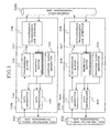
- Fig. 1 is a block diagram showing the construction of a first embodiment of the synchronous data transmission system according to the present invention. This embodiment concerns the transmission of voice as signal transmitted and received between such terminals.
- the synchronous data transmission system shown in Fig. 1 comprises a first and a second terminal 100 and 200 and a synchronous transmission line 300.
- Microphones 101 and 201 and loudspeakers 102 and 202 are connected to the first and second terminals 100 and 200, respectively.
- the first and second terminals 100, and 200 include sampling clock generators 103 and 203, data generators 104 and 204, data reproducers 105 and 205, transmission buffers 106 and 206, reception buffers 107 and 207, asynchronous transmission line interfaces 108 and 208, analog-to-digital (A/D) converters 109 and 209 and digital-to-analog (D/A) converters 110 and 210, respectively.
- the outputs of the sampling clock generators 103 and 203 are supplied to the data generators 104 and 204 and the data reproducers 105 and 205.
- the first and second terminals 100 and 200 have voice input/output functions constituted by microphones 101 and 201 and loudspeakers 102 and 202.
- the first and second terminals 100 and 200 perform voice communication with each other via the asynchronous transmission line 300.
- the sampling clock generators 103 and 203 generate sampling clocks of voice data in the first and second terminals 100 and 200.
- Voices inputted from the microphones 101 and 201 are supplied to the A/D converters 109 and 209, which in turn outputs digitalized data (i.e., digital data) to the data generators 104 and 204.
- the voice input signals are digitalized by using sampling clocks generated in the sampling clock generators 106 and 206.
- the data stored in the transmission buffers 106 and 206 have been packeted in certain time units (t).
- the data stored in the transmission buffers 108 and 208 are outputted via the asynchronous transmission line interfaces 108 and 208 to the asynchronous transmission line 300. This data transmission using the asynchronous line 300 is performed for the time unit (t).
- the data received from the asynchronous transmission line 300 are stored via the asynchronous transmission line interfaces 108 and 208 in the reception buffers 107 and 207.
- the data stored in the reception buffers 107 and 207 are transmitted to the data reproducers 105 and 205.
- the D/A converters 110 and 210 converts the outputs of the data reproducers 105 and 205 to analog data by using the sampling clocks generated in the sampling clock generators 103 and 203, and output the analog converted data to the loudspeakers 102 and 202.
- the reception buffers 107 and 207 can store data received from the asynchronous transmission line 300 for a plurality of times (n ⁇ t) in every unit time (t).
- the data reproducers 105 and 205 reproduce data when data for the plurality of times (n ⁇ t) has been stored.
- the operation of the synchronous data transmission system shown in Fig. 1 will now be described.
- a case will be considered, in which the first terminal 100 transmits voice data via the asynchronous transmission line 300 to the second terminal 200.
- the A/D converter 109 converts the data inputted as analog data from the microphone 101 to digital data.
- the conversion of the along to the digital data is performed by using the sampling clock generated in the sampling clock generator 103 in the first terminal 100.
- the frequency of the sampling clock is chosen to be f1 (Hz), and the accuracy of conversion is chosen to be m bits.
- the generator 104 executes data processing on the data sampled in the A/D converter 109 to generate packets each for each unit of processing in the asynchronous transmission line 300. This data processing is performed in units of times t (s).
- the data quantity w is expressed with t/f1*m bits.
- the data w is stored in the transmission buffer 106, and is outputted via the asynchronous transmission interface 108 to the asynchronous transmission line 300 for each time t.
- the data outputted to the asynchronous transmission line 300 is stored via the asynchronous transmission line interface 208 of the second terminal 200 in the reception buffer 207 therein.
- the reception buffer 207 has n buffer stages, and upon w data receipt (n - 1) times from the asynchronous transmission line 300, it transmits data in units of m bits to the data reproducer 205.
- the data reproducer 205 reproduces data by using the sampling clock generated in the sampling clock generator 203 in the second terminal 200.
- the frequency of the sampling clock at this time is chosen to be f2 (Hz).
- the time t1 of data generation in the first terminal 100 is expressed as w*f1/m
- the time t2 of data generation in the second terminal 200 is expressed as w*f2/m.
- t1 t2.
- the voice inputted from the microphone 101 of the first terminal 100 is outputted without interruption from the loudspeaker 202 of the second terminal 200.
- the sampling frequencies in the first and second terminals are not perfectly the same. Where f1 > f2, overflow of the received data occurs. Where f1 ⁇ f2, underflow of the received data occurs. In either case, missing of voice occurs.
- reception buffer 207 is an n-stage buffer
- overflow occurs therein with n*t/ ⁇ f(s).
- ⁇ f negative
- underflow occurs with t/ ⁇ f(s) in the reception buffer 207 as one-stage buffer.
- underflow occurs with n*t/ ⁇ f(s) in the reception buffer 207 as n-stage buffer. It will be seen that it is possible to extend the time until the overflow or underflow by n times and thus improve the quality of the synchronous data such as voice data.
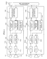
- Fig. 2 shows an embodiment, in which motion picture is transferred between the first and second terminals by using the asynchronous transmission line.
- Fig. 3 shows an embodiment, in which synchronous non-restricted digital communication line data of ISDN (integrated service digital network) or the like is transferred by using the asynchronous transmission line.
- the operations of these embodiments are substantially the same as in the case of Fig. 1.
- constituent elements corresponding to those in the above first embodiment are designated by like reference numerals.
- the second embodiment of the synchronous data transmission system according to the present invention shown in Fig. 2 comprises a first and a second terminal 100a and 200a and an asynchronous transmission line 300a.
- Image input units i.e., cameras
- image output units i.e., displays
- the first and second terminals 100a and 200a and the asynchronous transmission line 300a are the same as the corresponding elements in the first embodiment. In this embodiment, however, the A/D converters 109 and 209 and the D/A converters 110 and 210 shown in Fig. 1 are not provided.
- the third embodiment of the synchronous data transmission system shown in Fig. 3 comprises a first and a second terminal 100b and 200b and an asynchronous transmission line 300b.
- Synchronous non-restricted digital transmission lines 400 and 500 are connected to the first and second terminals 100b and 200b.
- the first and second terminals 100b and 200b and the asynchronous transmission line 300b are the same and operate in the same way as the first and second terminals 100a and 200a and the asynchronous transmission line 300a, respectively, in the second embodiment.
- Fig. 4 is a block diagram showing the construction of a third embodiment of the synchronous data transmission system according to the present invention.
- This synchronous data transmission system comprises a first and a second terminal 100c and 200c and an asynchronous transmission line 300c.
- microphones 101 and 202 and loudspeakers 102 and 202 are connected to the first and second terminals 100c and 200c.
- This third embodiment is different from the first embodiment shown in Fig.
- sampling clock synchronizing means such as a well-known PLL, phase-locked loop circuit or the like for synchronizing the sampling clocks of the sampling clock generators 103 and 203 in the first and second terminals 100c and 200c by inputting the output of the sampling clock generator 103 to the sampling clock generator 203.
- sampling clock synchronizing means is applicable to the second and third embodiments shown in Figs. 2 and 3 as well.
- the frequency difference between the sampling clocks generated in the sampling clock generators 103 and 203 in the first and second terminals 100c and 200c is eliminated by inputting the clock from the sampling clock generator 103 in the second terminal 100c to the sampling clock generator 203 in the second terminal 200c.
- this function it is possible to further reduce ⁇ f as described before in connection with the first embodiment shown in Fig. 1 and further alleviate the deterioration of the data quality compared to the first embodiment.
- Fig. 5 is a block diagram showing the construction of a fifth embodiment of the synchronous data transmission system according to the present invention.
- This embodiment comprises a first and a second terminal 100d and 200d and asynchronous transmission line 300d.
- Microphones 101 and 201 and loudspeakers 102 and 202 are connected to the first and second terminals 100d and 200d.
- the first terminal 100d and the asynchronous transmission line 300d are the same as the corresponding elements in the first embodiment.
- the data deterioration is further reduced in such a manner as to make the sampling clock frequency of the second terminal 200d closer to the sampling clock frequency of the first terminal 100d by estimating the sampling clock of the first terminal 100d on the basis of the data received from the asynchronous transmission line 100d.
- the data outputted from the first terminal 100d to the asynchronous transmission line 300d is transmitted in units of times t (s).
- the unit time t is measured in the terminal 100d, and different from time t2 measured in the second terminal 200d.
- This time difference is estimated in the asynchronous transmission line interface 208 and the sampling clock generator 203.
- the data quality deterioration is further reduced with this function along with the construction of the first embodiment shown in Fig. 1.
- the fifth embodiment has an effect that the data quality deterioration is reduced even with reduction of the number n of stages of the reception buffers 107 and 207 shown in Fig. 1.
Landscapes
- Engineering & Computer Science (AREA)
- Computer Networks & Wireless Communication (AREA)
- Synchronisation In Digital Transmission Systems (AREA)
- Time-Division Multiplex Systems (AREA)
Abstract
Description
Claims (10)
- A synchronous data transmission system for transmitting such data as voice or image data between a first and a second terminals via an asynchronous transmission line, wherein:the first and second terminals each comprise a data generator and a data reproducer operable under control of a clock from a sampling clock generator, and a transmission buffer and a plurality of reception buffer stages connected to the data generator and the data reproducer, respectively.
- A synchronous data transmission system for transmitting such data as voice or image data between a first and a second terminals via an asynchronous transmission line, wherein:the first and second terminals each comprise a data generator and a data reproducer operable under control of a clock from a sampling clock generator, and a transmission buffer and a plurality of reception buffer stages connected to the data generator and the data reproducer, respectively, and the first and second terminals each further comprise an asynchronous transmission line interface connected to the asynchronous transmission line.
- The synchronous data transmission system according to claim 1 or 2, wherein which further comprises a clock synchronizing means for synchronizing clocks generated in the sampling clock generators in the first and second terminals.
- The synchronous data transmission system according to claim 1 or 2, which further comprises a frequency difference eliminating means for eliminating the frequency difference between the clocks generated in the sampling clock generators in the first and second terminals.
- The synchronous data transmission system according to claim 1 or 2, wherein a synchronous data transmission line is connected to the data generators and the data reproducers in the first and second terminals.
- The synchronous data transmission system according to claim 2, wherein the sampling clock generators in the first and second terminals are controlled on the basis of the received data from the asynchronous transmission line interface.
- A synchronous data transmission system comprising a first and a second terminals and a synchronous transmission line connected between first and a second terminals for voice or image communication with each other, each terminal including a voice or image input means, a sampling clock generator, an A/D converter for digitalizing the output of the voice input means, a data generator, operable with the output of the sampling clock generator, for generating data on the basis of the output of the A/D converter, a transmission buffer receiving the generated data, a plurality of reception buffer stages supplied with the received data via a asynchronous transmission line, a data reproducer operable with the output of the sampling clock generator, for reproducing data from the plurality of reception buffer stages, a D/A converter for converting the reproduced data to an analog signal, a voice or image output means for outputting voice based on the D/A converter output, the data stored in the transmission buffer having been packeted in certain time units (t) and being outputted via asynchronous transmission line interface to the asynchronous transmission line for the time unit (t), the data received from the asynchronous transmission line being stored via the asynchronous transmission line interface in the reception buffer, the data stored in the reception buffer being transmitted to the data reproducer, the reception buffer being capable of storing data received from the asynchronous transmission line for a plurality of times (n × t) in every unit time (t), and the data reproducer reproducing data when data for the plurality of times (n ×t) has been stored.
- The synchronous data transmission system according to claim 7, further comprising a sampling clock synchronizing means for synchronizing the sampling clocks of the sampling clock generators in the first and second terminals by inputting the output of the sampling clock generator in one terminal to the sampling clock generator in another terminal.
- The synchronous data transmission system according to claim 7, wherein the frequency difference between the sampling clocks generated in the sampling clock generators in the first and second terminals is eliminated by inputting the clock from the sampling clock generator in one terminal to the sampling clock generator in another terminal.
- The synchronous data transmission system according to claim 7, wherein the sampling clock frequency of one terminal is made closer to the sampling clock frequency of another terminal by estimating the sampling clock on the basis of the data received from the asynchronous transmission line.
Applications Claiming Priority (2)
| Application Number | Priority Date | Filing Date | Title |
|---|---|---|---|
| JP2000236718A JP2002051031A (en) | 2000-08-04 | 2000-08-04 | Synchronous data transmission system |
| JP2000236718 | 2000-08-04 |
Publications (3)
| Publication Number | Publication Date |
|---|---|
| EP1178636A2 true EP1178636A2 (en) | 2002-02-06 |
| EP1178636A3 EP1178636A3 (en) | 2004-04-14 |
| EP1178636B1 EP1178636B1 (en) | 2006-09-06 |
Family
ID=18728719
Family Applications (1)
| Application Number | Title | Priority Date | Filing Date |
|---|---|---|---|
| EP20010117766 Expired - Lifetime EP1178636B1 (en) | 2000-08-04 | 2001-07-31 | Synchronous data transmission system |
Country Status (5)
| Country | Link |
|---|---|
| US (1) | US7359319B2 (en) |
| EP (1) | EP1178636B1 (en) |
| JP (1) | JP2002051031A (en) |
| CN (1) | CN1214559C (en) |
| DE (1) | DE60122841T2 (en) |
Families Citing this family (5)
| Publication number | Priority date | Publication date | Assignee | Title |
|---|---|---|---|---|
| JP3833164B2 (en) * | 2002-10-30 | 2006-10-11 | ティーオーエー株式会社 | Clock signal adjustment device |
| KR100747809B1 (en) * | 2005-09-03 | 2007-08-08 | 엘지전자 주식회사 | Method and system for displaying images in multiple image display devices |
| KR100678124B1 (en) * | 2006-01-26 | 2007-02-02 | 삼성전자주식회사 | Video communication data processing method of video communication terminal and video communication terminal |
| KR102415309B1 (en) * | 2020-06-16 | 2022-07-01 | 에스케이하이닉스 주식회사 | Interface device and method for operating the same |
| US11546128B2 (en) | 2020-06-16 | 2023-01-03 | SK Hynix Inc. | Device and computing system including the device |
Family Cites Families (33)
| Publication number | Priority date | Publication date | Assignee | Title |
|---|---|---|---|---|
| JPS5634248A (en) | 1979-08-30 | 1981-04-06 | Fujitsu Ltd | Frequency correction system in independent synchronization system |
| JPS62125728A (en) | 1985-11-26 | 1987-06-08 | Nec Corp | Clock transmission type synchronizing data transmission equipment |
| JPS63187942A (en) | 1987-01-30 | 1988-08-03 | Nippon Telegr & Teleph Corp <Ntt> | Data transmission system |
| US4843455A (en) * | 1987-08-20 | 1989-06-27 | Nec Corporation | Color television signal sampling clock phase control system |
| US5218640A (en) * | 1988-02-03 | 1993-06-08 | Sharp Kabushiki Kaisha | Voice recording and reproducing apparatus |
| JPH0695663B2 (en) | 1989-11-17 | 1994-11-24 | 三菱電機株式会社 | Independent synchronous terminal device accommodation method |
| JPH0583225A (en) * | 1991-09-19 | 1993-04-02 | Fujitsu Ltd | Time multiplex highway line designation method |
| JPH05183586A (en) | 1992-01-07 | 1993-07-23 | Toshiba Corp | Data device connection unit |
| US5453986A (en) * | 1993-01-08 | 1995-09-26 | Multi-Tech Systems, Inc. | Dual port interface for a computer-based multifunction personal communication system |
| JPH06252906A (en) | 1993-02-23 | 1994-09-09 | Hitachi Ltd | Synchronous control method |
| US5544315A (en) * | 1993-05-10 | 1996-08-06 | Communication Broadband Multimedia, Inc. | Network multimedia interface |
| JP2775572B2 (en) | 1993-06-14 | 1998-07-16 | 東京電力株式会社 | Current control method of self-excited voltage type AC / DC converter |
| JPH07170288A (en) * | 1993-12-15 | 1995-07-04 | Hitachi Ltd | Voice communication system and voice communication method |
| WO1995022233A1 (en) * | 1994-02-11 | 1995-08-17 | Newbridge Networks Corporation | Method of dynamically compensating for variable transmission delays in packet networks |
| EP0742976A1 (en) * | 1994-12-01 | 1996-11-20 | Koninklijke Philips Electronics N.V. | A communication system, a private automatic branch exchange, and a line card |
| US5606553A (en) * | 1995-02-28 | 1997-02-25 | Christie; Joseph M. | Cell processing for voice transmission |
| US5832031A (en) * | 1995-08-18 | 1998-11-03 | Hughes Electronics Corporation | Method and apparatus for performing cyclic redundancy check synchronization |
| US6307868B1 (en) * | 1995-08-25 | 2001-10-23 | Terayon Communication Systems, Inc. | Apparatus and method for SCDMA digital data transmission using orthogonal codes and a head end modem with no tracking loops |
| KR0145867B1 (en) * | 1995-08-28 | 1998-08-17 | 김광호 | Cdma type cellular phone and its data processing method |
| US6658250B1 (en) * | 1996-01-05 | 2003-12-02 | Hughes Electronics Corporation | System and method for a wide area wireless personal communication system incorporating advanced messaging |
| US5790538A (en) * | 1996-01-26 | 1998-08-04 | Telogy Networks, Inc. | System and method for voice Playout in an asynchronous packet network |
| JPH1093540A (en) | 1996-09-18 | 1998-04-10 | Hitachi Denshi Ltd | Data transmission method |
| US5940479A (en) * | 1996-10-01 | 1999-08-17 | Northern Telecom Limited | System and method for transmitting aural information between a computer and telephone equipment |
| US6611537B1 (en) * | 1997-05-30 | 2003-08-26 | Centillium Communications, Inc. | Synchronous network for digital media streams |
| US6044124A (en) * | 1997-08-22 | 2000-03-28 | Silicon Systems Design Ltd. | Delta sigma PLL with low jitter |
| EP0921666A3 (en) * | 1997-12-02 | 1999-07-14 | Nortel Networks Corporation | Speech reception via a packet transmission facility |
| IL123045A0 (en) * | 1998-01-25 | 1998-09-24 | Eci Telecom Ltd | Apparatus and method for digital telephony |
| US6433739B1 (en) * | 1998-03-17 | 2002-08-13 | Qualcomm, Incorporated | Method and apparatus for synchronizing base stations using remote synchronizing stations |
| US6389039B1 (en) * | 1998-10-22 | 2002-05-14 | Telefonaktiebolaget Lm Ericsson (Publ) | Asynchronous transfer on the cellular radio link |
| AU3457500A (en) * | 1999-03-31 | 2000-10-16 | Softfront, Inc. | System to transmit voice data over a packet network |
| US6658027B1 (en) * | 1999-08-16 | 2003-12-02 | Nortel Networks Limited | Jitter buffer management |
| US6975629B2 (en) * | 2000-03-22 | 2005-12-13 | Texas Instruments Incorporated | Processing packets based on deadline intervals |
| US20030112758A1 (en) * | 2001-12-03 | 2003-06-19 | Pang Jon Laurent | Methods and systems for managing variable delays in packet transmission |
-
2000
- 2000-08-04 JP JP2000236718A patent/JP2002051031A/en active Pending
-
2001
- 2001-07-31 EP EP20010117766 patent/EP1178636B1/en not_active Expired - Lifetime
- 2001-07-31 DE DE2001622841 patent/DE60122841T2/en not_active Expired - Lifetime
- 2001-08-02 US US09/919,873 patent/US7359319B2/en not_active Expired - Fee Related
- 2001-08-04 CN CNB011328215A patent/CN1214559C/en not_active Expired - Fee Related
Also Published As
| Publication number | Publication date |
|---|---|
| CN1214559C (en) | 2005-08-10 |
| US7359319B2 (en) | 2008-04-15 |
| JP2002051031A (en) | 2002-02-15 |
| DE60122841D1 (en) | 2006-10-19 |
| US20010053147A1 (en) | 2001-12-20 |
| DE60122841T2 (en) | 2007-04-19 |
| EP1178636B1 (en) | 2006-09-06 |
| CN1337801A (en) | 2002-02-27 |
| EP1178636A3 (en) | 2004-04-14 |
Similar Documents
| Publication | Publication Date | Title |
|---|---|---|
| US7158596B2 (en) | Communication system and method for sending and receiving data at a higher or lower sample rate than a network frame rate using a phase locked loop | |
| US7106224B2 (en) | Communication system and method for sample rate converting data onto or from a network using a high speed frequency comparison technique | |
| JP3687188B2 (en) | Packet transmission method | |
| US6055247A (en) | Data transmission method, data transmission apparatus and data transmission system | |
| US5353313A (en) | Transmission of a clock signal over an asynchronous data channel | |
| KR0127995B1 (en) | Communication system to match clock speed of independent network | |
| US7272202B2 (en) | Communication system and method for generating slave clocks and sample clocks at the source and destination ports of a synchronous network using the network frame rate | |
| JP3465227B2 (en) | Telephone terminal device | |
| JPH05507398A (en) | Synchronizer for terminal equipment in asynchronous transfer mode digital telecommunications networks | |
| JP3834825B2 (en) | Data processing system | |
| US7359319B2 (en) | Synchronous data transmission system | |
| GB2377866A (en) | Transmission of digital information of varying sample rates over a synchronous network | |
| US7359447B2 (en) | Asynchronous digital signal combiner and method of combining asynchronous digital signals in cable television return path | |
| EP2262138B1 (en) | Communication system for sending and receiving data onto and from a network at a network frame rate using a phase locked loop, sample rate conversion, or synchronizing clocks generated from the network frame rate | |
| JP2642043B2 (en) | SRTS control apparatus and method | |
| JPH066382A (en) | Packet communication device and communication system | |
| JPH04362827A (en) | Packet communication system | |
| JPH08154084A (en) | Digital transmission / reception method and apparatus | |
| JP2007189584A (en) | Digital wireless transmission system | |
| JPH05227115A (en) | Digital signal transmission method and apparatus | |
| JPH04368032A (en) | Frame conversion circuit | |
| JPH04100430A (en) | Audio cell image cell playback synchronizer | |
| JPH0936866A (en) | Data transmission system and data transmission method | |
| JPH08340329A (en) | Transmission system clock synchronizer | |
| JP2008153941A (en) | Voice packet reproducing apparatus, communication terminal and program having clock correction function |
Legal Events
| Date | Code | Title | Description |
|---|---|---|---|
| PUAI | Public reference made under article 153(3) epc to a published international application that has entered the european phase |
Free format text: ORIGINAL CODE: 0009012 |
|
| AK | Designated contracting states |
Kind code of ref document: A2 Designated state(s): AT BE CH CY DE DK ES FI FR GB GR IE IT LI LU MC NL PT SE TR |
|
| AX | Request for extension of the european patent |
Free format text: AL;LT;LV;MK;RO;SI |
|
| PUAL | Search report despatched |
Free format text: ORIGINAL CODE: 0009013 |
|
| AK | Designated contracting states |
Kind code of ref document: A3 Designated state(s): AT BE CH CY DE DK ES FI FR GB GR IE IT LI LU MC NL PT SE TR |
|
| AX | Request for extension of the european patent |
Extension state: AL LT LV MK RO SI |
|
| 17P | Request for examination filed |
Effective date: 20040303 |
|
| 17Q | First examination report despatched |
Effective date: 20040809 |
|
| AKX | Designation fees paid |
Designated state(s): DE FR GB IT |
|
| GRAP | Despatch of communication of intention to grant a patent |
Free format text: ORIGINAL CODE: EPIDOSNIGR1 |
|
| GRAS | Grant fee paid |
Free format text: ORIGINAL CODE: EPIDOSNIGR3 |
|
| GRAA | (expected) grant |
Free format text: ORIGINAL CODE: 0009210 |
|
| AK | Designated contracting states |
Kind code of ref document: B1 Designated state(s): DE FR GB IT |
|
| PG25 | Lapsed in a contracting state [announced via postgrant information from national office to epo] |
Ref country code: IT Free format text: LAPSE BECAUSE OF FAILURE TO SUBMIT A TRANSLATION OF THE DESCRIPTION OR TO PAY THE FEE WITHIN THE PRESCRIBED TIME-LIMIT;WARNING: LAPSES OF ITALIAN PATENTS WITH EFFECTIVE DATE BEFORE 2007 MAY HAVE OCCURRED AT ANY TIME BEFORE 2007. THE CORRECT EFFECTIVE DATE MAY BE DIFFERENT FROM THE ONE RECORDED. Effective date: 20060906 |
|
| REG | Reference to a national code |
Ref country code: GB Ref legal event code: FG4D |
|
| REF | Corresponds to: |
Ref document number: 60122841 Country of ref document: DE Date of ref document: 20061019 Kind code of ref document: P |
|
| ET | Fr: translation filed | ||
| PLBE | No opposition filed within time limit |
Free format text: ORIGINAL CODE: 0009261 |
|
| STAA | Information on the status of an ep patent application or granted ep patent |
Free format text: STATUS: NO OPPOSITION FILED WITHIN TIME LIMIT |
|
| 26N | No opposition filed |
Effective date: 20070607 |
|
| REG | Reference to a national code |
Ref country code: GB Ref legal event code: 732E Free format text: REGISTERED BETWEEN 20141023 AND 20141029 |
|
| REG | Reference to a national code |
Ref country code: FR Ref legal event code: TP Owner name: LENOVO INNOVATIONS LIMITED (HONG KONG), HK Effective date: 20141119 |
|
| REG | Reference to a national code |
Ref country code: FR Ref legal event code: PLFP Year of fee payment: 15 |
|
| PGFP | Annual fee paid to national office [announced via postgrant information from national office to epo] |
Ref country code: FR Payment date: 20150629 Year of fee payment: 15 |
|
| PGFP | Annual fee paid to national office [announced via postgrant information from national office to epo] |
Ref country code: IT Payment date: 20150727 Year of fee payment: 15 |
|
| PGFP | Annual fee paid to national office [announced via postgrant information from national office to epo] |
Ref country code: GB Payment date: 20160727 Year of fee payment: 16 Ref country code: DE Payment date: 20160726 Year of fee payment: 16 |
|
| PG25 | Lapsed in a contracting state [announced via postgrant information from national office to epo] |
Ref country code: FR Free format text: LAPSE BECAUSE OF NON-PAYMENT OF DUE FEES Effective date: 20160801 |
|
| REG | Reference to a national code |
Ref country code: FR Ref legal event code: ST Effective date: 20170331 |
|
| PG25 | Lapsed in a contracting state [announced via postgrant information from national office to epo] |
Ref country code: IT Free format text: LAPSE BECAUSE OF NON-PAYMENT OF DUE FEES Effective date: 20160731 |
|
| REG | Reference to a national code |
Ref country code: DE Ref legal event code: R119 Ref document number: 60122841 Country of ref document: DE |
|
| GBPC | Gb: european patent ceased through non-payment of renewal fee |
Effective date: 20170731 |
|
| PG25 | Lapsed in a contracting state [announced via postgrant information from national office to epo] |
Ref country code: GB Free format text: LAPSE BECAUSE OF NON-PAYMENT OF DUE FEES Effective date: 20170731 Ref country code: DE Free format text: LAPSE BECAUSE OF NON-PAYMENT OF DUE FEES Effective date: 20180201 |