EP1178552B1 - Fuel cell system - Google Patents
Fuel cell system Download PDFInfo
- Publication number
- EP1178552B1 EP1178552B1 EP01118215A EP01118215A EP1178552B1 EP 1178552 B1 EP1178552 B1 EP 1178552B1 EP 01118215 A EP01118215 A EP 01118215A EP 01118215 A EP01118215 A EP 01118215A EP 1178552 B1 EP1178552 B1 EP 1178552B1
- Authority
- EP
- European Patent Office
- Prior art keywords
- gas
- unit
- fuel cell
- hydrogen
- fuel
- Prior art date
- Legal status (The legal status is an assumption and is not a legal conclusion. Google has not performed a legal analysis and makes no representation as to the accuracy of the status listed.)
- Expired - Lifetime
Links
Images
Classifications
-
- H—ELECTRICITY
- H01—ELECTRIC ELEMENTS
- H01M—PROCESSES OR MEANS, e.g. BATTERIES, FOR THE DIRECT CONVERSION OF CHEMICAL ENERGY INTO ELECTRICAL ENERGY
- H01M8/00—Fuel cells; Manufacture thereof
- H01M8/04—Auxiliary arrangements, e.g. for control of pressure or for circulation of fluids
- H01M8/04007—Auxiliary arrangements, e.g. for control of pressure or for circulation of fluids related to heat exchange
- H01M8/04067—Heat exchange or temperature measuring elements, thermal insulation, e.g. heat pipes, heat pumps, fins
-
- C—CHEMISTRY; METALLURGY
- C01—INORGANIC CHEMISTRY
- C01B—NON-METALLIC ELEMENTS; COMPOUNDS THEREOF; METALLOIDS OR COMPOUNDS THEREOF NOT COVERED BY SUBCLASS C01C
- C01B3/00—Hydrogen; Gaseous mixtures containing hydrogen; Separation of hydrogen from mixtures containing it; Purification of hydrogen; Reversible storage of hydrogen
- C01B3/02—Production of hydrogen; Production of gaseous mixtures containing hydrogen
- C01B3/32—Production of hydrogen; Production of gaseous mixtures containing hydrogen by reaction of gaseous or liquid organic compounds with gasifying agents, e.g. water, carbon dioxide or air
-
- H—ELECTRICITY
- H01—ELECTRIC ELEMENTS
- H01M—PROCESSES OR MEANS, e.g. BATTERIES, FOR THE DIRECT CONVERSION OF CHEMICAL ENERGY INTO ELECTRICAL ENERGY
- H01M8/00—Fuel cells; Manufacture thereof
- H01M8/04—Auxiliary arrangements, e.g. for control of pressure or for circulation of fluids
- H01M8/04007—Auxiliary arrangements, e.g. for control of pressure or for circulation of fluids related to heat exchange
- H01M8/04014—Heat exchange using gaseous fluids; Heat exchange by combustion of reactants
-
- H—ELECTRICITY
- H01—ELECTRIC ELEMENTS
- H01M—PROCESSES OR MEANS, e.g. BATTERIES, FOR THE DIRECT CONVERSION OF CHEMICAL ENERGY INTO ELECTRICAL ENERGY
- H01M8/00—Fuel cells; Manufacture thereof
- H01M8/06—Combination of fuel cells with means for production of reactants or for treatment of residues
- H01M8/0606—Combination of fuel cells with means for production of reactants or for treatment of residues with means for production of gaseous reactants
- H01M8/0612—Combination of fuel cells with means for production of reactants or for treatment of residues with means for production of gaseous reactants from carbon-containing material
-
- H—ELECTRICITY
- H01—ELECTRIC ELEMENTS
- H01M—PROCESSES OR MEANS, e.g. BATTERIES, FOR THE DIRECT CONVERSION OF CHEMICAL ENERGY INTO ELECTRICAL ENERGY
- H01M8/00—Fuel cells; Manufacture thereof
- H01M8/06—Combination of fuel cells with means for production of reactants or for treatment of residues
- H01M8/0662—Treatment of gaseous reactants or gaseous residues, e.g. cleaning
-
- C—CHEMISTRY; METALLURGY
- C01—INORGANIC CHEMISTRY
- C01B—NON-METALLIC ELEMENTS; COMPOUNDS THEREOF; METALLOIDS OR COMPOUNDS THEREOF NOT COVERED BY SUBCLASS C01C
- C01B2203/00—Integrated processes for the production of hydrogen or synthesis gas
- C01B2203/02—Processes for making hydrogen or synthesis gas
- C01B2203/0205—Processes for making hydrogen or synthesis gas containing a reforming step
- C01B2203/0227—Processes for making hydrogen or synthesis gas containing a reforming step containing a catalytic reforming step
- C01B2203/0233—Processes for making hydrogen or synthesis gas containing a reforming step containing a catalytic reforming step the reforming step being a steam reforming step
-
- C—CHEMISTRY; METALLURGY
- C01—INORGANIC CHEMISTRY
- C01B—NON-METALLIC ELEMENTS; COMPOUNDS THEREOF; METALLOIDS OR COMPOUNDS THEREOF NOT COVERED BY SUBCLASS C01C
- C01B2203/00—Integrated processes for the production of hydrogen or synthesis gas
- C01B2203/02—Processes for making hydrogen or synthesis gas
- C01B2203/025—Processes for making hydrogen or synthesis gas containing a partial oxidation step
-
- C—CHEMISTRY; METALLURGY
- C01—INORGANIC CHEMISTRY
- C01B—NON-METALLIC ELEMENTS; COMPOUNDS THEREOF; METALLOIDS OR COMPOUNDS THEREOF NOT COVERED BY SUBCLASS C01C
- C01B2203/00—Integrated processes for the production of hydrogen or synthesis gas
- C01B2203/04—Integrated processes for the production of hydrogen or synthesis gas containing a purification step for the hydrogen or the synthesis gas
- C01B2203/0435—Catalytic purification
- C01B2203/044—Selective oxidation of carbon monoxide
-
- C—CHEMISTRY; METALLURGY
- C01—INORGANIC CHEMISTRY
- C01B—NON-METALLIC ELEMENTS; COMPOUNDS THEREOF; METALLOIDS OR COMPOUNDS THEREOF NOT COVERED BY SUBCLASS C01C
- C01B2203/00—Integrated processes for the production of hydrogen or synthesis gas
- C01B2203/04—Integrated processes for the production of hydrogen or synthesis gas containing a purification step for the hydrogen or the synthesis gas
- C01B2203/0465—Composition of the impurity
- C01B2203/047—Composition of the impurity the impurity being carbon monoxide
-
- C—CHEMISTRY; METALLURGY
- C01—INORGANIC CHEMISTRY
- C01B—NON-METALLIC ELEMENTS; COMPOUNDS THEREOF; METALLOIDS OR COMPOUNDS THEREOF NOT COVERED BY SUBCLASS C01C
- C01B2203/00—Integrated processes for the production of hydrogen or synthesis gas
- C01B2203/06—Integration with other chemical processes
- C01B2203/066—Integration with other chemical processes with fuel cells
-
- C—CHEMISTRY; METALLURGY
- C01—INORGANIC CHEMISTRY
- C01B—NON-METALLIC ELEMENTS; COMPOUNDS THEREOF; METALLOIDS OR COMPOUNDS THEREOF NOT COVERED BY SUBCLASS C01C
- C01B2203/00—Integrated processes for the production of hydrogen or synthesis gas
- C01B2203/12—Feeding the process for making hydrogen or synthesis gas
- C01B2203/1205—Composition of the feed
- C01B2203/1211—Organic compounds or organic mixtures used in the process for making hydrogen or synthesis gas
- C01B2203/1217—Alcohols
- C01B2203/1223—Methanol
-
- C—CHEMISTRY; METALLURGY
- C01—INORGANIC CHEMISTRY
- C01B—NON-METALLIC ELEMENTS; COMPOUNDS THEREOF; METALLOIDS OR COMPOUNDS THEREOF NOT COVERED BY SUBCLASS C01C
- C01B2203/00—Integrated processes for the production of hydrogen or synthesis gas
- C01B2203/12—Feeding the process for making hydrogen or synthesis gas
- C01B2203/1288—Evaporation of one or more of the different feed components
- C01B2203/1294—Evaporation by heat exchange with hot process stream
-
- H—ELECTRICITY
- H01—ELECTRIC ELEMENTS
- H01M—PROCESSES OR MEANS, e.g. BATTERIES, FOR THE DIRECT CONVERSION OF CHEMICAL ENERGY INTO ELECTRICAL ENERGY
- H01M8/00—Fuel cells; Manufacture thereof
- H01M8/06—Combination of fuel cells with means for production of reactants or for treatment of residues
- H01M8/0606—Combination of fuel cells with means for production of reactants or for treatment of residues with means for production of gaseous reactants
- H01M8/0612—Combination of fuel cells with means for production of reactants or for treatment of residues with means for production of gaseous reactants from carbon-containing material
- H01M8/0618—Reforming processes, e.g. autothermal, partial oxidation or steam reforming
-
- H—ELECTRICITY
- H01—ELECTRIC ELEMENTS
- H01M—PROCESSES OR MEANS, e.g. BATTERIES, FOR THE DIRECT CONVERSION OF CHEMICAL ENERGY INTO ELECTRICAL ENERGY
- H01M8/00—Fuel cells; Manufacture thereof
- H01M8/06—Combination of fuel cells with means for production of reactants or for treatment of residues
- H01M8/0662—Treatment of gaseous reactants or gaseous residues, e.g. cleaning
- H01M8/0668—Removal of carbon monoxide or carbon dioxide
-
- Y—GENERAL TAGGING OF NEW TECHNOLOGICAL DEVELOPMENTS; GENERAL TAGGING OF CROSS-SECTIONAL TECHNOLOGIES SPANNING OVER SEVERAL SECTIONS OF THE IPC; TECHNICAL SUBJECTS COVERED BY FORMER USPC CROSS-REFERENCE ART COLLECTIONS [XRACs] AND DIGESTS
- Y02—TECHNOLOGIES OR APPLICATIONS FOR MITIGATION OR ADAPTATION AGAINST CLIMATE CHANGE
- Y02E—REDUCTION OF GREENHOUSE GAS [GHG] EMISSIONS, RELATED TO ENERGY GENERATION, TRANSMISSION OR DISTRIBUTION
- Y02E60/00—Enabling technologies; Technologies with a potential or indirect contribution to GHG emissions mitigation
- Y02E60/30—Hydrogen technology
- Y02E60/50—Fuel cells
Definitions
- the present invention relates to a fuel cell system according to the preamble of claim 1
- a generic fuel cell system is known from EP 861 802 A2.
- all subsystems such as preheating for one Fuel / water mixture, evaporator, gas generation, gas purification and exhaust aftertreatment integrated in a common plate arrangement.
- gas cleaning for removal of the resulting thermal energy adjacent to the Preheating arranged.
- the disadvantage of this system is the fact that the fuel / water mixture Recordable thermal energy not in all operating conditions sufficient for sufficient cooling of the gas cleaning, so that in the Fuel cell still undesirable temperature peaks occur. Furthermore is disadvantageous that the fuel / water mixture already in the preheating unit at least partially evaporated, so that the preheating of a phase mixture flowing through liquid and gaseous fuel or water.
- the Heat capacity of the cooling medium depends strongly on the phase state, so that in areas with gaseous coolant may not be sufficient Cooling capacity is available and it comes locally to overheating can.
- the object of the invention is to provide a fuel cell system which is compact, has an improved system efficiency and a Reliable heat balance for both the gas cleaning unit and for the Fuel cell ensured.
- the admission of the heat exchanger with the emerging from the fuel cell Coolant which is not the subject of the present invention, has the advantage on that the coolant circuit of the fuel cell is relieved, so that the second heat exchanger must dissipate less heat energy. This can thus smaller, which is desirable especially in mobile applications is.
- this arrangement again the thermal Reduced voltages in the evaporator unit and the system efficiency improved.
- the coolant circuit of the fuel cell can also be used to cool a further, designed as a reformate cooler heat exchanger can be used.
- a reformate cooler heat exchanger can be used.
- Even with this arrangement can be a reliable heat balance guaranteed both for the gas cleaning unit, as well as for the fuel cell become.
- the system efficiency is improved by the preheating unit and reduces the burden on the evaporator unit.
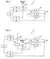
- the fuel cell system generally designated 1, according to FIG. 1 has a Heat exchanger 11, an evaporator unit 9, a gas generating unit 2, a Gas cleaning unit 3, and a fuel cell 4 with an anode compartment 6, a Cathode space 5 and a refrigerator 7. Furthermore, a catalytic oxidation unit 8 provided. With the help of a metering pump 12 is a raw fuel / water mixture conveyed from a reservoir, not shown. The Raw fuel / water mixture is preheated in the heat exchanger 11 and then evaporated in the evaporator unit 9, wherein the evaporator unit 9 heated directly or indirectly by the oxidation unit 8 or in any other way becomes.
- the raw fuel / water mixture is in the heat exchanger 11 by thermal Contact with the hydrogen-rich, emerging from the gas purification unit 3, heated gas heated.
- This is the hydrogen-rich, purified gas cooled simultaneously, so that the heat exchanger 11 at the same time the function of so-called Reformatkühlers takes over.
- This is the hydrogen-rich, purified Gas cooled to suitable for the fuel cell 4 temperatures.
- the gas generating unit 2 is then from the gaseous fuel / water mixture and optionally air by means of partial oxidation and / or steam reforming generates a hydrogen-rich gas.
- Used for the gas generating unit 2 requires heating, this in turn can be directly or indirectly via the oxidation unit 8, by thermal contact with the gas cleaning unit 3 or in done otherwise.
- the hydrogen-rich gas is usually carbon monoxide contained, which for the existing in the anode compartment 6 of the fuel cell 4 Catalysts acts detrimental. Because of this, there is between the gas generating unit 2 and the anode compartment 6 of the fuel cell 4, a gas cleaning unit 3 provided. This is preferably a Device for selective catalytic oxidation of carbon monoxide with addition of oxygen.
- gas purification units 3 For example, a membrane cleaning unit can be used.
- the gas purification unit 3 is in thermal contact with an associated cooling unit 14.
- This cooling unit 14 can be cooled, for example, by means of a suitable coolant become.
- the gas purification unit 3 it is also possible for the gas purification unit 3 to be in contact to cool with an endothermic reaction.
- the cooling unit 14 may also be designed as a gas generating unit in which an endothermic Steam reforming takes place.
- the cooling unit 14 is already a much of the thermal energy removed from the gas cleaning unit 3.
- Heat exchanger 11 is used in particular for intercepting temperature peaks and simultaneously provides a thermal safety reserve for the protection of the fuel cell 4 represents.
- the cathode compartment 5 of the fuel cell 4 is by means of a compressor 13 a oxygen-containing gas, preferably ambient air, supplied under pressure.
- a oxygen-containing gas preferably ambient air
- the cooling space 7 of the fuel cell 4 is of a suitable coolant, preferably a water / glycol mixture, flows through. In this case, the fuel cell 4 is at a predetermined operating temperature held.
- the embodiment shows only the basic structure of a Fuel cell 4.
- the evaporator unit 9, the gas generating unit 2, the Gas cleaning unit 3 or other components of the fuel cell system 1 also be executed in several stages.
- FIG. 2 Another embodiment of a fuel cell system that is not subject matter of the present invention is shown in FIG. 2, wherein like parts with identical Reference signs are marked. Notwithstanding Fig. 1 is in this arrangement the heat exchanger 11 is acted upon by the coolant of the fuel cell 4, wherein the Coolant is supplied to the heat exchanger 11 downstream of the cooling chamber 7.
- the crude fuel / water mixture instead of the hydrogen-rich, cleaned gas from the gas cleaning unit 3 by the hot cooling medium preheated from the cooling chamber 7 before it is fed into the evaporator unit 9.
- Downstream of the heat exchanger 11 is additionally in this embodiment further heat exchanger 15 is arranged in the coolant flow of the fuel cell 4, which additionally acted upon by a cooling medium, preferably ambient air becomes.
- This third heat exchanger 16 is then turn the from the gas cleaning unit 3 leaking hydrogen-rich, purified gas before the entry into the anode compartment 6 to a bearable for the fuel cell 4 temperature cooled.
- the need for the second heat exchanger 15 depends on the operating conditions in the fuel cell system. If the coolant after the flow through the heat exchanger 11 already under all operating conditions has a sufficiently low temperature, can on the second heat exchanger 15 also be waived.
- This arrangement has the advantage that the coolant circuit of the fuel cell 4 is relieved, so that the second heat exchanger 15 less heat energy must pay. This can thus be made smaller, which is especially true at mobile applications is desirable. At the same time, even with this arrangement in turn reduces the thermal stresses in the evaporator unit 9 and improves system efficiency.
Landscapes
- Chemical & Material Sciences (AREA)
- Engineering & Computer Science (AREA)
- Chemical Kinetics & Catalysis (AREA)
- General Chemical & Material Sciences (AREA)
- Sustainable Energy (AREA)
- Sustainable Development (AREA)
- Manufacturing & Machinery (AREA)
- Electrochemistry (AREA)
- Life Sciences & Earth Sciences (AREA)
- Combustion & Propulsion (AREA)
- Organic Chemistry (AREA)
- Health & Medical Sciences (AREA)
- General Health & Medical Sciences (AREA)
- Inorganic Chemistry (AREA)
- Fuel Cell (AREA)
- Hydrogen, Water And Hydrids (AREA)
Description
Die vorliegende Erfindung betrifft ein Brennstoffzellensystem nach dem Oberbegriff
des Patentanspruchs 1.The present invention relates to a fuel cell system according to the preamble
of
Herkömmliche Brennstoffzellen verwenden als Brennstoff Wasserstoff, welcher in der Brennstoffzelle vorgeschalteten Stufen aus einem Gemisch aus einem flüssigen Kraftstoff, beispielsweise aus Methanol, und Wasser hergestellt wird. Da bei der Herstellung des Wasserstoffs üblicherweise auch für die Brennstoffzelle schädliches Kohlenmonoxid entsteht, wird zusätzlich noch eine Gasreinigungseinheit zwischengeschaltet, so dass eine Beaufschlagung der Anodenseite der Brennstoffzelle mit im wesentlichen reinem Wasserstoff erfolgt. Weiterhin ist zum Verdampfen des Kraftstoffes beziehungsweise des Wassers eine Verdampfereinheit vorgesehen. Schliesslich ist zur Vermeidung von Umweltbelastungen eine Abgasnachbehandlungseinheit vorgesehen, in der alle brennbaren Bestandteile der Brennstoffzellenabgase möglichst vollständig umgesetzt werden.Conventional fuel cells use hydrogen as fuel, which in the Fuel cell upstream stages of a mixture of a liquid fuel, for example, from methanol, and water is produced. Because in the production of hydrogen usually harmful to the fuel cell Carbon monoxide is produced, in addition, a gas cleaning unit is interposed, so that an admission of the anode side of the fuel cell with im essentially pure hydrogen. Furthermore, to vaporize the fuel or the water provided an evaporator unit. After all is to avoid environmental pollution an exhaust aftertreatment unit provided, in which all combustible components of the fuel cell exhaust gases as possible be fully implemented.
Ein gattungsgemässes Brennstoffzellensystem ist aus der EP 861 802 A2 bekannt. Bei diesem Brennstoffzellensystem sind alle Teilsysteme, wie Vorwärmung für ein Kraftstoff/Wassergemisch, Verdampfer, Gaserzeugung, Gasreinigung und Abgasnachbehandlung in einer gemeinsamen Plattenanordnung integriert. Hierbei ist die Gasreinigung zur Abfuhr der dort anfallenden thermischen Energie benachbart zu der Vorwärmeinheit angeordnet.A generic fuel cell system is known from EP 861 802 A2. In this fuel cell system, all subsystems, such as preheating for one Fuel / water mixture, evaporator, gas generation, gas purification and exhaust aftertreatment integrated in a common plate arrangement. Here is the Gas cleaning for removal of the resulting thermal energy adjacent to the Preheating arranged.
Nachteilig bei diesem System ist die Tatsache, dass die von dem Kraftstoff/Wassergemisch aufnehmbare thermische Energie nicht in allen Betriebsbedingungen zur ausreichenden Kühlung der Gasreinigung ausreicht, so dass in der Brennstoffzelle noch unerwünschte Temperaturspitzen auftreten. Weiterhin ist nachteilig, dass das Kraftstoff/Wassergemisch bereits in der Vorwärmeinheit zumindest teilweise verdampft, so dass die Vorwärmeinheit von einem Phasengemisch aus flüssigem und gasförmigen Kraftstoff beziehungsweise Wasser durchströmt wird. Die Wärmekapazität des Kühlmediums hängt jedoch stark vom Phasenzustand ab, so dass in Bereichen mit gasförmigem Kühlmittel unter Umständen keine ausreichende Kühlleistung zur Verfügung steht und es somit örtlich zu Überhitzungen kommen kann. The disadvantage of this system is the fact that the fuel / water mixture Recordable thermal energy not in all operating conditions sufficient for sufficient cooling of the gas cleaning, so that in the Fuel cell still undesirable temperature peaks occur. Furthermore is disadvantageous that the fuel / water mixture already in the preheating unit at least partially evaporated, so that the preheating of a phase mixture flowing through liquid and gaseous fuel or water. The Heat capacity of the cooling medium, however, depends strongly on the phase state, so that in areas with gaseous coolant may not be sufficient Cooling capacity is available and it comes locally to overheating can.
Weiterhin ist aus der US 5,344,721 A1 ein Brennstoffzellensystem bekannt, bei dem Kraftstoff und Wasser separat zugeführt werden. Hierbei sind für den Kraftstoff und das Wasser separate Vorwärmeinheiten und Verdampfer vorgesehen. Somit werden bei dieser Anordnung eine Vielzahl von Bauteilen benötigt, was insbesondere bei mobilen Anwendungen im Hinblick auf den zur Verfügung stehenden Bauraum, Kosten und Gewicht nicht akzeptabel ist.Furthermore, from US 5,344,721 A1 a fuel cell system is known in which Fuel and water are supplied separately. Here are for the fuel and the water is provided separate preheating units and evaporators. Thus be in this arrangement, a large number of components needed, which is particularly true for mobile Applications in terms of available space, costs and weight is unacceptable.
Aufgabe der Erfindung ist die Bereitstellung eines Brennstoffzellensystems, welches kompakt aufgebaut ist, einen verbesserten Systemwirkungsgrad aufweist und einen zuverlässigen Wärmehaushalt sowohl für die Gasreinigungseinheit als auch für die Brennstoffzelle gewährleistet.The object of the invention is to provide a fuel cell system which is compact, has an improved system efficiency and a Reliable heat balance for both the gas cleaning unit and for the Fuel cell ensured.
Diese Aufgabe wird gelöst durch ein Brennstoffzellensystem mit den Merkmalen des
Patentanspruchs 1.This object is achieved by a fuel cell system with the features of
Durch die Kombination einer Gasreinigungseinheit mit einer zugehörigen Kühleinheit und einem der Gasreinigungseinheit nachgeschalteten Wärmetauscher zur Vorwärmung des Rohkraftstoff/Wassergemisches kann selbst bei Lastwechseln gewährleistet werden, dass das dem Anodenraum der Brennstoffzelle zugeführte wasserstoffreiche, gereinigte Gas eine für die Brennstoffzelle verträgliche Temperatur aufweist. Unzulässige Temperaturspitzen werden somit vermieden. Gleichzeitig wird diese dem wasserstoffreichen, gereinigten Gas entzogene Energie dem Rohkraftstoff/Wassergemisch zugeführt. Dadurch verringert sich die erforderliche Verdampferleistung und der Systemwirkungsgrad wird verbessert. Gleichzeitig wird die Beanspruchung, insbesondere auftretende Thermospannungen, der Verdampfereinheit durch den verringerten Temperaturgradient gesenkt. Dadurch kann die Lebensdauer und das dynamische Verhalten der Verdampfereinheit verbessert werden. Im Vergleich zu Systemen mit getrennter Kraftstoff- und Wasserzufuhr kann zumindest eine Vorwärmeinheit beziehungsweise eine Verdampfereinheit eingespart werden.By combining a gas cleaning unit with an associated cooling unit and one of the gas cleaning unit downstream heat exchanger for preheating of the raw fuel / water mixture can be guaranteed even during load changes be that supplied to the anode compartment of the fuel cell hydrogen-rich, purified gas a compatible for the fuel cell temperature having. Impermissible temperature peaks are thus avoided. At the same time this energy extracted from the hydrogen-rich, purified gas is the raw fuel / water mixture fed. This reduces the required evaporator capacity and the system efficiency is improved. At the same time the Stress, especially occurring thermal stresses, the evaporator unit lowered by the reduced temperature gradient. This can extend the life and the dynamic behavior of the evaporator unit can be improved. in the At least compared to systems with separate fuel and water supply a preheating unit or an evaporator unit can be saved.
Die Beaufschlagung des Wärmetauschers mit dem aus der Brennstoffzelle austretenden Kühlmittel, die nicht Gegenstand der vorliegenden Erfindung ist, weist den Vorteil auf, dass der Kühlmittelkreislauf der Brennstoffzelle entlastet wird, so dass der zweite Wärmetauscher weniger Wärmeenergie abführen muss. Dieser kann somit kleiner ausgeführt werden, was insbesondere bei mobilen Anwendungen wünschenswert ist. Gleichzeitig werden auch bei dieser Anordnung wiederum die thermischen Spannungen in der Verdampfereinheit reduziert und der Systemwirkungsgrad verbessert. The admission of the heat exchanger with the emerging from the fuel cell Coolant, which is not the subject of the present invention, has the advantage on that the coolant circuit of the fuel cell is relieved, so that the second heat exchanger must dissipate less heat energy. This can thus smaller, which is desirable especially in mobile applications is. At the same time, in this arrangement again the thermal Reduced voltages in the evaporator unit and the system efficiency improved.
Der Kühlmittelkreislauf der Brennstoffzelle kann außerdem auch zur Kühlung eines weiteren, als Reformatkühler ausgeführten Wärmetauschers verwendet werden. In diesem Fall kann es notwendig sein, zwischen die Vorwärmeinheit und den Reformatkühler noch einen weiteren, mit einem Kühlmedium beaufschlagten Wärmetauscher vorzusehen. Auch mit dieser Anordnung kann ein zuverlässiger Wärmehaushalt sowohl für die Gasreinigungseinheit, als auch für die Brennstoffzelle gewährleistet werden. Gleichzeitig wird durch die Vorwärmeinheit der Systemwirkungsgrad verbessert und die Belastung für die Verdampfereinheit reduziert.The coolant circuit of the fuel cell can also be used to cool a further, designed as a reformate cooler heat exchanger can be used. In In this case it may be necessary between the preheating unit and the reformate cooler yet another, acted upon with a cooling medium heat exchanger provided. Even with this arrangement can be a reliable heat balance guaranteed both for the gas cleaning unit, as well as for the fuel cell become. At the same time, the system efficiency is improved by the preheating unit and reduces the burden on the evaporator unit.
Weitere Vorteile gehen aus den Unteransprüchen und der Beschreibung hervor. Die Erfindung wird nun anhand der beigefügten Zeichnung näher beschrieben. In dieser zeigt
- Fig. 1
- ein erstes Ausführungsbeispiel eines vereinfachtes Blockschaltbildes eines Brennstoffzellensystems und
- Fig. 2
- ein zweites Ausführungsbeispiel eines vereinfachtes Blockschaltbildes eines Brennstoffzellensystems, das nicht Gegenstand der vorliegenden Erfindung ist.
- Fig. 1
- a first embodiment of a simplified block diagram of a fuel cell system and
- Fig. 2
- A second embodiment of a simplified block diagram of a fuel cell system, which is not the subject of the present invention.
Das insgesamt mit 1 bezeichnete Brennstoffzellensystem gemäss Fig. 1 weist einen
Wärmetauscher 11, eine Verdampfereinheit 9, eine Gaserzeugungseinheit 2, eine
Gasreinigungseinheit 3, sowie eine Brennstoffzelle 4 mit einem Anodenraum 6, einem
Kathodenraum 5 und einem Kühlraum 7 auf. Weiterhin ist eine katalytische Oxidationseinheit
8 vorgesehen. Mit Hilfe einer Dosierpumpe 12 wird ein Rohkraftstoff/Wassergemisch
aus einem nicht dargestellten Vorratsbehälter gefördert. Das
Rohkraftstoff/Wassergemisch wird in dem Wärmetauscher 11 vorgewärmt und anschliessend
in der Verdampfereinheit 9 verdampft, wobei die Verdampfereinheit 9
direkt oder indirekt durch die Oxidationseinheit 8 oder auf sonstige Weise beheizt
wird. Das Rohkraftstoff/Wassergemisch wird in dem Wärmetauscher 11 durch thermischen
Kontakt mit dem aus der Gasreinigungseinheit 3 austretenden wasserstoffreichen,
gereinigten Gas erwärmt. Hierbei wird das wasserstoffreiche, gereinigte Gas
gleichzeitig abgekühlt, so dass der Wärmetauscher 11 gleichzeitig die Funktion eines
sogenannten Reformatkühlers übernimmt. Hierbei wird das wasserstoffreiche, gereinigte
Gas auf für die Brennstoffzelle 4 geeignete Temperaturen abgekühlt. The fuel cell system, generally designated 1, according to FIG. 1 has a
In der Gaserzeugungseinheit 2 wird dann aus dem gasförmigen Kraftstoff/Wassergemisch
und gegebenenfalls Luft mittels partieller Oxidation und/oder Wasserdampfreformierung
ein wasserstoffreiches Gas erzeugt. Wird für die Gaserzeugungseinheit
2 eine Beheizung benötigt, so kann dies wiederum direkt oder indirekt über die Oxidationseinheit
8, durch thermischen Kontakt mit der Gasreinigungseinheit 3 oder in
sonstiger Weise erfolgen. In dem wasserstoffreichen Gas ist üblicherweise auch Kohlenmonoxid
enthalten, welches für die im Anodenraum 6 der Brennstoffzelle 4 vorhandenen
Katalysatoren schädlich wirkt. Aus diesem Grund ist zwischen der Gaserzeugungseinheit
2 und dem Anodenraum 6 der Brennstoffzelle 4 eine Gasreinigungseinheit
3 vorgesehen. Hierbei handelt es sich vorzugsweise um eine
Vorrichtung zur selektiven katalytischen Oxidation des Kohlenmonoxids unter Zugabe
von Sauerstoff. Es können jedoch auch andere geeignete Gasreinigungseinheiten 3,
beispielsweise eine Membranreinigungseinheit, verwendet werden. Die Gasreinigungseinheit
3 steht in thermischen Kontakt mit einer zugehörigen Kühleinheit 14.
Diese Kühleinheit 14 kann beispielsweise mit Hilfe eines geeigneten Kühlmittels gekühlt
werden. Alternativ ist es auch möglich, die Gasreinigungseineheit 3 durch Kontakt
mit einer endothermen Reaktion zu kühlen. In diesem Falle kann beispielsweise
die Kühleinheit 14 auch als Gaserzeugungseinheit ausgebildet sein, in der eine endotherme
Wasserdampfreformierung abläuft. Durch die Kühleinheit 14 wird bereits ein
grosser Teil der thermischen Energie aus der Gasreinigungseinheit 3 abgeführt. Der
Wärmetauscher 11 dient insbesondere zum Abfangen von Temperaturspitzen und
stellt gleichzeitig eine thermische Sicherheitsreserve zum Schutz der Brennstoffzelle 4
dar.In the gas generating
Dem Kathodenraum 5 der Brennstoffzelle 4 wird mit Hilfe eines Verdichters 13 ein
sauerstoffhaltiges Gas, vorzugsweise Umgebungsluft, unter Druck zugeführt. Alternativ
kann der Brennstoffzelle 4 auch mit Hilfe eines Gebläses Umgebungsluft bei Umgebungsdruck
zugeführt werden. Der Kühlraum 7 der Brennstoffzelle 4 wird von
einem geeigneten Kühlmittel, vorzugsweise einem Wasser/Glykolgemisch, durchströmt.
Dabei wird die Brennstoffzelle 4 auf einer vorgegebenen Betriebstemperatur
gehalten. Das Ausführungsbeispiel zeigt lediglich den prinzipiellen Aufbau einer
Brennstoffzelle 4. Der genaue Aufbau einer solchen Brennstoffzelle 4 beziehungsweise
eines Brennstoffzellenstapels, sowie die geeignete Anordnung von einem oder
mehreren Kühlräumen 7 ist aus dem Stand der Technik bekannt und wird daher hier
nicht näher erläutert Nach dem Durchströmen der Brennstoffzelle 4 wird das Anodenabgas
mit der Abluft aus dem Kathodenraum 5 in einem Mischelement 10 gemischt
und der katalytischen Oxidationseinheit 8 zugeführt. Dort werden an einem
geeigneten Katalysator, vorzugsweise einem Edelmetallkatalysator, alle brennbaren
Bestandteile der Brennstoffzellenabgase möglichst vollständig umgesetzt. Anstelle
des Kathodenabgases kann auch ein anderes sauerstoffhaltiges Gas stromauf der
katalytischen Oxidationseinheit 8 dem Anodenabgas beigemischt werden.The cathode compartment 5 of the
Selbstverständlich können die Verdampfereinheit 9, die Gaserzeugungseinheit 2, die
Gasreinigungseinheit 3 oder sonstige Komponenten des Brennstoffzellensystems 1
auch mehrstufig ausgeführt werden.Of course, the
Durch die Kombination einer Gasreinigungseinheit 3 mit separater Kühleinheit 14 und
einem Wärmetauscher 11 zur Vorwärmung des Rohkraftstoff/Wassergemisches kann
selbst bei Lastwechseln sichergestellt werden, dass sich das dem Anodenraum 6 der
Brennstoffzelle 4 zugeführte wasserstoffreiche, gereinigte Gas auf einem für die
Brennstoffzelle 4 erträglichen Temperaturniveau befindet. Unzulässige Temperaturspitzen
werden somit vermieden. Gleichzeitig wird diese dem wasserstoffreichen,
gereinigten Gas entzogene Energie dem Rohkraftstoff/Wassergemisch zugeführt.
Dadurch verringert sich die erforderliche Verdampferleistung und der Systemwirkungsgrad
wird verbessert. Ferner wird die Beanspruchung, insbesondere auftretende
Thermospannungen, der Verdampfereinheit 9 durch den verringerten
Temperaturgradient gesenkt. Dadurch kann die Lebensdauer und das dynamische
Verhalten der Verdampfereinheit 9 verbessert werden. Im Vergleich zu Systemen mit
getrennter Kraftstoff und Wasserzufuhr kann zumindest eine Vorwärmeinheit beziehungsweise
eine Verdampfereinheit eingespart werden.By combining a
Ein weiteres Ausführungsbeispiel eines Brennstoffzellensystems, das nicht Gegenstand
der vorliegenden Erfindung ist, zeigt Fig. 2, wobei gleiche Teile mit identischen
Bezugszeichen gekennzeichnet sind. Abweichend von Fig. 1 wird in dieser Anordnung
der Wärmetauscher 11 vom Kühlmittel der Brennstoffzelle 4 beaufschlagt, wobei das
Kühlmittel dem Wärmetauscher 11 stromab des Kühlraums 7 zugeführt wird. In diesem
Fall wird also das Rohkraftstoff/Wassergemisch anstelle durch das wasserstoffreiche,
gereinigte Gas aus der Gasreinigungseinheit 3 durch das heisse Kühlmedium
aus dem Kühlraum 7 vorgewärmt, bevor es in die Verdampfereinheit 9 geführt wird.
Stromab des Wärmetauschers 11 ist in diesem Ausführungsbeispiel zusätzlich ein
weiterer Wärmetauscher 15 im Kühlmittelstrom der Brennstoffzelle 4 angeordnet,
welcher zusätzlich von einem Kühlmedium, vorzugsweise Umgebungsluft, beaufschlagt
wird. Dadurch wird die Temperatur des Kühlmittels weiter verringert, bevor
es anschliessend in einen als sogenannter Reformatkühler dienenden dritten Wärmetauscher
16 eintritt. Durch diesen dritten Wärmetauscher 16 wird dann wiederum das
aus der Gasreinigungseinheit 3 austretende wasserstoffreiche, gereinigte Gas vor
dem Eintritt in den Anodenraum 6 auf eine für die Brennstoffzelle 4 erträgliche Temperatur
gekühlt. Die Notwendigkeit für den zweiten Wärmetauscher 15 hängt von
den Betriebsbedingungen im Brennstoffzellensystem ab. Falls das Kühlmittel nach
dem Durchströmen des Wärmetauschers 11 bereits unter allen Betriebsbedingungen
eine ausreichend niedere Temperatur aufweist, kann auf den zweiten Wärmetauscher
15 auch verzichtet werden.Another embodiment of a fuel cell system that is not subject matter
of the present invention is shown in FIG. 2, wherein like parts with identical
Reference signs are marked. Notwithstanding Fig. 1 is in this arrangement
the
Diese Anordnung weist den Vorteil auf, dass der Kühlmittelkreislauf der Brennstoffzelle
4 entlastet wird, so dass der zweite Wärmetauscher 15 weniger Wärmeenergie
abführen muss. Dieser kann somit kleiner ausgeführt werden, was insbesondere bei
mobilen Anwendungen wünschenswert ist. Gleichzeitig werden auch bei dieser Anordnung
wiederum die thermischen Spannungen in der Verdampfereinheit 9 reduziert
und der Systemwirkungsgrad verbessert.This arrangement has the advantage that the coolant circuit of the
Claims (2)
- Fuel cell system (1) comprising a heat exchanger (11) for pre-warming a raw-fuel/water mixture, an evaporator unit (9) for producing a gaseous educt gas flow from the pre-warmed raw-fuel/water mixture, a gas-generating unit (2) for producing a hydrogen-rich gas from the educt gas flow, a cooled gas-purging unit (3) for selectively removing carbon monoxide from the hydrogen-rich gas, and at least one fuel cell (4) for converting said hydrogen-rich purged gas, wherein the at least one fuel cell (4) includes an anode room (6), through which the purged hydrogen-rich gas flows, a cathode room (5), through which an oxygen-containing medium flows, and a cooling room (7), through which a coolant flows,
characterized in that the heat exchanger (11) is arranged downstream of the gas-purging unit (3) and is charged with the purged hydrogen-rich gas for heating, wherein the gas-purging unit (3) includes a separate cooling unit (14). - Fuel cell system according to claim 1,
characterized in that a catalytic oxidation unit (8) is further provided for supplying thermal energy, which unit is in thermal contact with the evaporator unit (9) and possibly with the gas-generating unit (2) and which is charged with the exhaust gases from the anode and cathode rooms (6, 5).
Priority Applications (1)
| Application Number | Priority Date | Filing Date | Title |
|---|---|---|---|
| EP04029693A EP1523055A1 (en) | 2000-08-03 | 2001-07-28 | Fuel cell system |
Applications Claiming Priority (2)
| Application Number | Priority Date | Filing Date | Title |
|---|---|---|---|
| DE10037825 | 2000-08-03 | ||
| DE10037825A DE10037825A1 (en) | 2000-08-03 | 2000-08-03 | The fuel cell system |
Related Child Applications (1)
| Application Number | Title | Priority Date | Filing Date |
|---|---|---|---|
| EP04029693A Division EP1523055A1 (en) | 2000-08-03 | 2001-07-28 | Fuel cell system |
Publications (3)
| Publication Number | Publication Date |
|---|---|
| EP1178552A2 EP1178552A2 (en) | 2002-02-06 |
| EP1178552A3 EP1178552A3 (en) | 2004-04-14 |
| EP1178552B1 true EP1178552B1 (en) | 2005-09-14 |
Family
ID=7651181
Family Applications (2)
| Application Number | Title | Priority Date | Filing Date |
|---|---|---|---|
| EP01118215A Expired - Lifetime EP1178552B1 (en) | 2000-08-03 | 2001-07-28 | Fuel cell system |
| EP04029693A Withdrawn EP1523055A1 (en) | 2000-08-03 | 2001-07-28 | Fuel cell system |
Family Applications After (1)
| Application Number | Title | Priority Date | Filing Date |
|---|---|---|---|
| EP04029693A Withdrawn EP1523055A1 (en) | 2000-08-03 | 2001-07-28 | Fuel cell system |
Country Status (3)
| Country | Link |
|---|---|
| US (1) | US6667122B2 (en) |
| EP (2) | EP1178552B1 (en) |
| DE (2) | DE10037825A1 (en) |
Families Citing this family (11)
| Publication number | Priority date | Publication date | Assignee | Title |
|---|---|---|---|---|
| US20040043265A1 (en) * | 2002-09-04 | 2004-03-04 | General Electric Company | Staged fuel cell with intercooling |
| JP4292368B2 (en) * | 2002-12-12 | 2009-07-08 | ソニー株式会社 | Fuel cell and electronic device equipped with the same |
| US7354706B2 (en) * | 2003-09-09 | 2008-04-08 | The Regents Of The University Of Colorado, A Body Corporate | Use of photopolymerization for amplification and detection of a molecular recognition event |
| US20090163375A1 (en) | 2003-09-09 | 2009-06-25 | Bowman Christopher N | Use of Photopolymerization for Amplification and Detection of a Molecular Recognition Event |
| US20070082245A1 (en) * | 2005-10-12 | 2007-04-12 | Volker Druenert | Evaporative cooling system for fuel cell systems using cathode product water |
| DE102007018705A1 (en) * | 2007-04-18 | 2008-10-23 | Viessmann Werke Gmbh & Co Kg | Fuel cell system and method for operating a fuel cell system |
| US20090137405A1 (en) * | 2007-11-16 | 2009-05-28 | Christopher Bowman | Detection of nucleic acid biomarkers using polymerization-based amplification |
| US7923162B2 (en) * | 2008-03-19 | 2011-04-12 | Dana Canada Corporation | Fuel cell assemblies with integrated reactant-conditioning heat exchangers |
| DK180361B1 (en) | 2019-10-17 | 2021-02-04 | Blue World Technologies Holding ApS | Fuel cell system with a multi-stream heat exchanger, its use and method of its operation |
| DK180518B1 (en) * | 2019-10-17 | 2021-06-03 | Blue World Technologies Holding ApS | Fuel cell system with a combined fuel evaporation and cathode gas heater unit, its use and method of its operation |
| CN114744243B (en) * | 2021-04-05 | 2024-09-27 | 武汉众宇动力系统科技有限公司 | Hydrogen circulation supply method for hydrogen fuel cell |
Family Cites Families (15)
| Publication number | Priority date | Publication date | Assignee | Title |
|---|---|---|---|---|
| US4352863A (en) * | 1981-01-21 | 1982-10-05 | Energy Research Corporation | Apparatus and method for producing high pressure steam in a fuel cell system |
| US4670359A (en) * | 1985-06-10 | 1987-06-02 | Engelhard Corporation | Fuel cell integrated with steam reformer |
| DE3688990T2 (en) * | 1985-06-10 | 1994-05-11 | Us Energy | Fuel cell with integrated water vapor converter. |
| JP3352716B2 (en) * | 1992-03-31 | 2002-12-03 | 株式会社東芝 | Solid polymer electrolyte fuel cell device |
| DE19545186A1 (en) * | 1995-12-04 | 1997-06-05 | Siemens Ag | Method for operating a high-temperature fuel cell system and high-temperature fuel cell system |
| JP3129670B2 (en) * | 1997-02-28 | 2001-01-31 | 三菱電機株式会社 | Fuel reformer |
| DE19727588C1 (en) * | 1997-06-28 | 1999-02-18 | Dbb Fuel Cell Engines Gmbh | Device for generating a hydrogen-rich and low-carbon monoxide gas |
| DE19754013C2 (en) * | 1997-12-05 | 2000-10-26 | Dbb Fuel Cell Engines Gmbh | Device and method for steam reforming a hydrocarbon |
| DE19822691A1 (en) * | 1998-05-20 | 1999-11-25 | Volkswagen Ag | Fuel cell system for a vehicle |
| DE19822689A1 (en) * | 1998-05-20 | 1999-11-25 | Volkswagen Ag | Fuel cell system, especially as drive system of motor vehicle |
| DE19832389C2 (en) * | 1998-07-18 | 2003-04-24 | Ballard Power Systems | The fuel cell system |
| US6120923A (en) * | 1998-12-23 | 2000-09-19 | International Fuel Cells, Llc | Steam producing hydrocarbon fueled power plant employing a PEM fuel cell |
| DE19903168C2 (en) * | 1999-01-27 | 2002-06-20 | Xcellsis Gmbh | Spiral heat exchanger |
| EP1181241B1 (en) * | 1999-05-03 | 2005-08-24 | Nuvera Fuel Cells | Autothermal reforming system with integrated shift beds, preferential oxidationreactor, auxiliary reactor, and system controls |
| US6551732B1 (en) * | 2000-09-18 | 2003-04-22 | Air Products And Chemicals, Inc. | Use of fuel cell cathode effluent in a fuel reformer to produce hydrogen for the fuel cell anode |
-
2000
- 2000-08-03 DE DE10037825A patent/DE10037825A1/en not_active Withdrawn
-
2001
- 2001-07-28 EP EP01118215A patent/EP1178552B1/en not_active Expired - Lifetime
- 2001-07-28 EP EP04029693A patent/EP1523055A1/en not_active Withdrawn
- 2001-07-28 DE DE50107406T patent/DE50107406D1/en not_active Expired - Fee Related
- 2001-08-03 US US09/921,312 patent/US6667122B2/en not_active Expired - Fee Related
Also Published As
| Publication number | Publication date |
|---|---|
| US20020028364A1 (en) | 2002-03-07 |
| DE50107406D1 (en) | 2005-10-20 |
| EP1178552A2 (en) | 2002-02-06 |
| EP1523055A1 (en) | 2005-04-13 |
| EP1178552A3 (en) | 2004-04-14 |
| US6667122B2 (en) | 2003-12-23 |
| DE10037825A1 (en) | 2002-05-16 |
Similar Documents
| Publication | Publication Date | Title |
|---|---|---|
| DE102007039594B4 (en) | Energy generation unit with at least one high-temperature fuel cell | |
| DE69123042T2 (en) | System for generating energy using fuel cells with molten carbonates | |
| EP0921584B1 (en) | Device for steam reforming of hydrocarbons | |
| EP1033769B1 (en) | Fuel cell system having an associated hydrogen generating device | |
| EP0859421B1 (en) | Fuel cell system with liquid fuel | |
| DE19832389C2 (en) | The fuel cell system | |
| EP1178552B1 (en) | Fuel cell system | |
| DE10306234A1 (en) | Arrangement for supplying air to fuel cell passes at least some of the thermal energy of exhaust gases remaining after passing through expander to at least one of flows of material fed to combustion | |
| EP1921703B1 (en) | Fuel cell system with means for preheating cathode air | |
| DE102017001564B4 (en) | Method for starting a fuel cell arrangement and fuel cell arrangement | |
| EP1082774A1 (en) | Fuel cell system and method for generating electrical energy using a fuel cell system | |
| EP1104039A2 (en) | Fuel cell system, gas supply system and method for operating the system | |
| DE19706584C2 (en) | High temperature fuel cells with heating of the reaction gas | |
| EP1679757B1 (en) | Fuel cell system | |
| EP2038951A1 (en) | Fuel cell system and method for influencing the thermal balance of a fuel cell system | |
| DE19943248B4 (en) | Method for operating a fuel cell system and arrangement for carrying out the method | |
| EP1860378B1 (en) | Burner and associated fuel cell system | |
| DE102004046922A1 (en) | Fuel cell system and method for operating a fuel cell system | |
| DE10025667B4 (en) | A method of operating a gas generating device in a fuel cell system | |
| DE19717067C2 (en) | Reforming reactor plant, in particular for steam reforming of methanol | |
| DE19958404A1 (en) | Device for the selective catalytic oxidation of carbon monoxide | |
| DE102022204105A1 (en) | Heat exchanger with integrated start-up heating | |
| AT9611U1 (en) | ENERGY GENERATION UNIT WITH AT LEAST ONE HIGH TEMPERATURE FUEL CELL | |
| DE102007017787A1 (en) | Reformer with a catalyst device and a heat exchanger and method for operating a reformer | |
| DE102004040664A1 (en) | Heat exchangers, generators and heating and / or air conditioning |
Legal Events
| Date | Code | Title | Description |
|---|---|---|---|
| PUAI | Public reference made under article 153(3) epc to a published international application that has entered the european phase |
Free format text: ORIGINAL CODE: 0009012 |
|
| AK | Designated contracting states |
Kind code of ref document: A2 Designated state(s): AT BE CH CY DE DK ES FI FR GB GR IE IT LI LU MC NL PT SE TR |
|
| AX | Request for extension of the european patent |
Free format text: AL;LT;LV;MK;RO;SI |
|
| RAP1 | Party data changed (applicant data changed or rights of an application transferred) |
Owner name: BALLARD POWER SYSTEMS AG |
|
| PUAL | Search report despatched |
Free format text: ORIGINAL CODE: 0009013 |
|
| AK | Designated contracting states |
Kind code of ref document: A3 Designated state(s): AT BE CH CY DE DK ES FI FR GB GR IE IT LI LU MC NL PT SE TR |
|
| AX | Request for extension of the european patent |
Extension state: AL LT LV MK RO SI |
|
| 17P | Request for examination filed |
Effective date: 20040823 |
|
| AKX | Designation fees paid |
Designated state(s): DE FR GB IT |
|
| 17Q | First examination report despatched |
Effective date: 20041126 |
|
| GRAP | Despatch of communication of intention to grant a patent |
Free format text: ORIGINAL CODE: EPIDOSNIGR1 |
|
| GRAS | Grant fee paid |
Free format text: ORIGINAL CODE: EPIDOSNIGR3 |
|
| GRAA | (expected) grant |
Free format text: ORIGINAL CODE: 0009210 |
|
| AK | Designated contracting states |
Kind code of ref document: B1 Designated state(s): DE FR GB IT |
|
| PG25 | Lapsed in a contracting state [announced via postgrant information from national office to epo] |
Ref country code: GB Free format text: LAPSE BECAUSE OF FAILURE TO SUBMIT A TRANSLATION OF THE DESCRIPTION OR TO PAY THE FEE WITHIN THE PRESCRIBED TIME-LIMIT Effective date: 20050914 |
|
| REG | Reference to a national code |
Ref country code: GB Ref legal event code: FG4D Free format text: NOT ENGLISH |
|
| REF | Corresponds to: |
Ref document number: 50107406 Country of ref document: DE Date of ref document: 20051020 Kind code of ref document: P |
|
| RAP2 | Party data changed (patent owner data changed or rights of a patent transferred) |
Owner name: NUCELLSYS GMBH |
|
| GBV | Gb: ep patent (uk) treated as always having been void in accordance with gb section 77(7)/1977 [no translation filed] |
Effective date: 20050914 |
|
| ET | Fr: translation filed | ||
| PLBE | No opposition filed within time limit |
Free format text: ORIGINAL CODE: 0009261 |
|
| STAA | Information on the status of an ep patent application or granted ep patent |
Free format text: STATUS: NO OPPOSITION FILED WITHIN TIME LIMIT |
|
| REG | Reference to a national code |
Ref country code: FR Ref legal event code: CD Ref country code: FR Ref legal event code: TP |
|
| 26N | No opposition filed |
Effective date: 20060615 |
|
| PGFP | Annual fee paid to national office [announced via postgrant information from national office to epo] |
Ref country code: FR Payment date: 20090716 Year of fee payment: 9 |
|
| PGFP | Annual fee paid to national office [announced via postgrant information from national office to epo] |
Ref country code: DE Payment date: 20090722 Year of fee payment: 9 |
|
| PGFP | Annual fee paid to national office [announced via postgrant information from national office to epo] |
Ref country code: IT Payment date: 20090728 Year of fee payment: 9 |
|
| REG | Reference to a national code |
Ref country code: FR Ref legal event code: ST Effective date: 20110331 |
|
| PG25 | Lapsed in a contracting state [announced via postgrant information from national office to epo] |
Ref country code: DE Free format text: LAPSE BECAUSE OF NON-PAYMENT OF DUE FEES Effective date: 20110201 |
|
| REG | Reference to a national code |
Ref country code: DE Ref legal event code: R119 Ref document number: 50107406 Country of ref document: DE Effective date: 20110201 |
|
| PG25 | Lapsed in a contracting state [announced via postgrant information from national office to epo] |
Ref country code: IT Free format text: LAPSE BECAUSE OF NON-PAYMENT OF DUE FEES Effective date: 20100728 Ref country code: FR Free format text: LAPSE BECAUSE OF NON-PAYMENT OF DUE FEES Effective date: 20100802 |