EP1679757B1 - Fuel cell system - Google Patents
Fuel cell system Download PDFInfo
- Publication number
- EP1679757B1 EP1679757B1 EP05111852A EP05111852A EP1679757B1 EP 1679757 B1 EP1679757 B1 EP 1679757B1 EP 05111852 A EP05111852 A EP 05111852A EP 05111852 A EP05111852 A EP 05111852A EP 1679757 B1 EP1679757 B1 EP 1679757B1
- Authority
- EP
- European Patent Office
- Prior art keywords
- fuel cell
- cell system
- burner
- gas
- exhaust gas
- Prior art date
- Legal status (The legal status is an assumption and is not a legal conclusion. Google has not performed a legal analysis and makes no representation as to the accuracy of the status listed.)
- Active
Links
- 239000000446 fuel Substances 0.000 title claims description 125
- 239000007789 gas Substances 0.000 claims description 142
- 239000007800 oxidant agent Substances 0.000 claims description 30
- 238000002485 combustion reaction Methods 0.000 claims description 17
- MYMOFIZGZYHOMD-UHFFFAOYSA-N Dioxygen Chemical compound O=O MYMOFIZGZYHOMD-UHFFFAOYSA-N 0.000 claims description 13
- 229910001882 dioxygen Inorganic materials 0.000 claims description 13
- UFHFLCQGNIYNRP-UHFFFAOYSA-N Hydrogen Chemical compound [H][H] UFHFLCQGNIYNRP-UHFFFAOYSA-N 0.000 claims description 12
- 238000009413 insulation Methods 0.000 claims description 9
- 230000001590 oxidative effect Effects 0.000 claims description 9
- 239000001257 hydrogen Substances 0.000 claims description 7
- 229910052739 hydrogen Inorganic materials 0.000 claims description 7
- 238000010438 heat treatment Methods 0.000 claims description 6
- 230000005611 electricity Effects 0.000 claims description 5
- 238000006243 chemical reaction Methods 0.000 claims 1
- 238000001816 cooling Methods 0.000 description 4
- 238000000034 method Methods 0.000 description 3
- 230000001419 dependent effect Effects 0.000 description 2
- 230000010354 integration Effects 0.000 description 2
- 238000013021 overheating Methods 0.000 description 2
- XLYOFNOQVPJJNP-UHFFFAOYSA-N water Substances O XLYOFNOQVPJJNP-UHFFFAOYSA-N 0.000 description 2
- QVGXLLKOCUKJST-UHFFFAOYSA-N atomic oxygen Chemical compound [O] QVGXLLKOCUKJST-UHFFFAOYSA-N 0.000 description 1
- 238000010586 diagram Methods 0.000 description 1
- 239000002828 fuel tank Substances 0.000 description 1
- 238000009434 installation Methods 0.000 description 1
- 238000002955 isolation Methods 0.000 description 1
- 239000001301 oxygen Substances 0.000 description 1
- 229910052760 oxygen Inorganic materials 0.000 description 1
- 238000010248 power generation Methods 0.000 description 1
- 239000007787 solid Substances 0.000 description 1
- 238000011144 upstream manufacturing Methods 0.000 description 1
Images


Classifications
-
- H—ELECTRICITY
- H01—ELECTRIC ELEMENTS
- H01M—PROCESSES OR MEANS, e.g. BATTERIES, FOR THE DIRECT CONVERSION OF CHEMICAL ENERGY INTO ELECTRICAL ENERGY
- H01M8/00—Fuel cells; Manufacture thereof
- H01M8/04—Auxiliary arrangements, e.g. for control of pressure or for circulation of fluids
- H01M8/04007—Auxiliary arrangements, e.g. for control of pressure or for circulation of fluids related to heat exchange
- H01M8/04014—Heat exchange using gaseous fluids; Heat exchange by combustion of reactants
- H01M8/04022—Heating by combustion
-
- H—ELECTRICITY
- H01—ELECTRIC ELEMENTS
- H01M—PROCESSES OR MEANS, e.g. BATTERIES, FOR THE DIRECT CONVERSION OF CHEMICAL ENERGY INTO ELECTRICAL ENERGY
- H01M8/00—Fuel cells; Manufacture thereof
- H01M8/04—Auxiliary arrangements, e.g. for control of pressure or for circulation of fluids
- H01M8/04223—Auxiliary arrangements, e.g. for control of pressure or for circulation of fluids during start-up or shut-down; Depolarisation or activation, e.g. purging; Means for short-circuiting defective fuel cells
- H01M8/04268—Heating of fuel cells during the start-up of the fuel cells
-
- H—ELECTRICITY
- H01—ELECTRIC ELEMENTS
- H01M—PROCESSES OR MEANS, e.g. BATTERIES, FOR THE DIRECT CONVERSION OF CHEMICAL ENERGY INTO ELECTRICAL ENERGY
- H01M8/00—Fuel cells; Manufacture thereof
- H01M8/06—Combination of fuel cells with means for production of reactants or for treatment of residues
- H01M8/0606—Combination of fuel cells with means for production of reactants or for treatment of residues with means for production of gaseous reactants
- H01M8/0612—Combination of fuel cells with means for production of reactants or for treatment of residues with means for production of gaseous reactants from carbon-containing material
-
- H—ELECTRICITY
- H01—ELECTRIC ELEMENTS
- H01M—PROCESSES OR MEANS, e.g. BATTERIES, FOR THE DIRECT CONVERSION OF CHEMICAL ENERGY INTO ELECTRICAL ENERGY
- H01M8/00—Fuel cells; Manufacture thereof
- H01M8/06—Combination of fuel cells with means for production of reactants or for treatment of residues
- H01M8/0662—Treatment of gaseous reactants or gaseous residues, e.g. cleaning
-
- H—ELECTRICITY
- H01—ELECTRIC ELEMENTS
- H01M—PROCESSES OR MEANS, e.g. BATTERIES, FOR THE DIRECT CONVERSION OF CHEMICAL ENERGY INTO ELECTRICAL ENERGY
- H01M8/00—Fuel cells; Manufacture thereof
- H01M8/10—Fuel cells with solid electrolytes
- H01M8/12—Fuel cells with solid electrolytes operating at high temperature, e.g. with stabilised ZrO2 electrolyte
- H01M2008/1293—Fuel cells with solid oxide electrolytes
-
- H—ELECTRICITY
- H01—ELECTRIC ELEMENTS
- H01M—PROCESSES OR MEANS, e.g. BATTERIES, FOR THE DIRECT CONVERSION OF CHEMICAL ENERGY INTO ELECTRICAL ENERGY
- H01M2250/00—Fuel cells for particular applications; Specific features of fuel cell system
- H01M2250/20—Fuel cells in motive systems, e.g. vehicle, ship, plane
-
- Y—GENERAL TAGGING OF NEW TECHNOLOGICAL DEVELOPMENTS; GENERAL TAGGING OF CROSS-SECTIONAL TECHNOLOGIES SPANNING OVER SEVERAL SECTIONS OF THE IPC; TECHNICAL SUBJECTS COVERED BY FORMER USPC CROSS-REFERENCE ART COLLECTIONS [XRACs] AND DIGESTS
- Y02—TECHNOLOGIES OR APPLICATIONS FOR MITIGATION OR ADAPTATION AGAINST CLIMATE CHANGE
- Y02E—REDUCTION OF GREENHOUSE GAS [GHG] EMISSIONS, RELATED TO ENERGY GENERATION, TRANSMISSION OR DISTRIBUTION
- Y02E60/00—Enabling technologies; Technologies with a potential or indirect contribution to GHG emissions mitigation
- Y02E60/30—Hydrogen technology
- Y02E60/50—Fuel cells
-
- Y—GENERAL TAGGING OF NEW TECHNOLOGICAL DEVELOPMENTS; GENERAL TAGGING OF CROSS-SECTIONAL TECHNOLOGIES SPANNING OVER SEVERAL SECTIONS OF THE IPC; TECHNICAL SUBJECTS COVERED BY FORMER USPC CROSS-REFERENCE ART COLLECTIONS [XRACs] AND DIGESTS
- Y02—TECHNOLOGIES OR APPLICATIONS FOR MITIGATION OR ADAPTATION AGAINST CLIMATE CHANGE
- Y02T—CLIMATE CHANGE MITIGATION TECHNOLOGIES RELATED TO TRANSPORTATION
- Y02T90/00—Enabling technologies or technologies with a potential or indirect contribution to GHG emissions mitigation
- Y02T90/40—Application of hydrogen technology to transportation, e.g. using fuel cells
Definitions
- the present invention relates to a fuel cell system of a motor vehicle.
- a fuel cell system typically includes a fuel cell and a burner or residual gas burner or main burner.
- an anode gas containing hydrogen gas and a cathode gas containing oxygen gas are turned into electricity. Hydrogen gas and oxygen gas are converted into water and electricity.
- the main burner the anode exhaust gas of the fuel cell and the cathode exhaust gas of the fuel cell are burned to obtain low-emission emissions. The released heat can be used to preheat the educts of the fuel cell process.
- a fuel cell system of this type can be provided in a motor vehicle as an additional power source to ensure the power supply in a vehicle with high power requirements.
- the fuel cell system may be a generator driven by an internal combustion engine of the vehicle, so-called alternator, in phases of low engine power support.
- the present invention is concerned with the problem of providing for a fuel cell system of the type mentioned in an improved embodiment, which in particular has a relatively short preheating, and in which a fuel guide is avoided within the insulation box.
- the invention is based on the general idea of integrating into the fuel cell system a conventional burner or starting burner, with which a hydrogen-containing fuel can be burned with an oxidant, for example air, containing oxygen gas.
- the integration of this starting burner into the fuel cell system takes place in such a way that the combustion exhaust gases of the starting burner during a start-up operation in the fuel cell system form the anode gas or the anode exhaust gas or the cathode gas or the cathode exhaust gas or mixed with the respective gas.
- the respective gas can be preheated intensively, which leads to a corresponding increase in temperature in the component through which gas flows.
- a preheating of the anode gas or the cathode gas thus leads to a corresponding preheating of the fuel cell.
- the fuel cell is flowed through on the cathode side or on the anode side by the starting burner exhaust gases.
- preheating the anode exhaust gases or the cathode exhaust gases only the main burner or its exhaust gases are initially preheated. Since usually the heat of the main burner or the heat of the main burner exhaust gases is used for preheating the educts of the fuel cell system, the preheating of the anode exhaust gases or the cathode exhaust gases leads to the same destination.
- the essential difference of this variant is that in this case the starting burner exhaust gases do not reach the fuel cell. In that regard, here is an indirect heating of the fuel cell.
- the conventionally operating starting burner can be put into operation quickly and, immediately after its start-up, it already provides heat in its exhaust gases, which can be used to preheat the fuel cell system or the fuel cell.
- the starting phase of the fuel cell system ie the time until the relevant components of the fuel cell system their respective minimum operating temperature can be shortened thereby.
- the starting burner is installed in a gas line of the fuel cell system, which is present anyway and accordingly only slightly modified to realize the starting burner.
- the starting burner may be installed in an anode gas line, which supplies the anode gas of the fuel cell in normal operation of the fuel cell system.
- the starting burner may be installed in a cathode gas line, which supplies the cathode gas of the fuel cell during normal operation of the fuel cell system. It is also possible to install the starting burner in an oxidizer line which supplies the oxygen gas-containing oxidizer to the main burner during normal operation of the fuel cell system.
- the main burner via such an additional Oxidator Ober oxidizer, that is usually air, fed to get colder main burner exhaust gases.
- This is important in order to be able to build a heat exchanger downstream of the main burner as compactly as possible while at the same time avoiding the risk of overheating of this heat exchanger.
- the integration of the starting burner into a gas line which is present in any case in the fuel cell system reduces the space required for the realization of the fuel cell system according to the invention Effort. Furthermore, the fuel cell system according to the invention thereby builds compact.
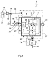
- an inventive fuel cell system 1 of a motor vehicle comprises at least one fuel cell 2, a main burner 3, a heat exchanger 4 and a reformer 5.
- the fuel cell 2 receives in normal operation via an anode gas line 6, a hydrogen gas-containing anode gas and a cathode gas line 7, an oxygen gas-containing cathode gas.
- the fuel cell 2 runs in normal operation from a conventional fuel cell process, in which the hydrogen gas and the oxygen gas react to give off electricity, so-called power generation of anode gas and cathode gas.
- the electricity generated in this case can be tapped off via power connections (not shown here) and provided, for example, to the electrical system of the vehicle.
- the fuel cell system 1 serves as an additional power supply of the vehicle.
- a cathode exhaust gas line 8 leads cathode exhaust gas from the fuel cell 2 to the main burner 3.
- Cathode exhaust gas is a cathode gas with a reduced oxygen content.
- an anode exhaust gas line 9 carries anode exhaust gas from the fuel cell 2 to the main burner 3.
- Anode exhaust gas is thereby anode gas with reduced hydrogen content and significantly increased water content.
- combustion of anode exhaust gas and cathode exhaust gas takes place in the main burner 3, resulting in hot combustion exhaust gases, which are referred to below as main burner exhaust gases.
- main burner exhaust gases Via a main burner exhaust gas line 10, the main burner exhaust gases are discharged from the main burner 3.
- the main burner exhaust gas line 10 leads through the heat exchanger 4 and optionally by a stationary heater 11.
- the heat exchanger 4 is integrated on the one hand in the main burner exhaust gas line 10 and on the other hand in the cathode gas line 7. In this way, the hot main burner exhaust gas can deliver heat to the cathode gas to preheat it.
- the above-mentioned parking heater 11 may also be configured in the form of a heat exchanger, on the one hand in the main burner exhaust gas line 10 and on the other hand in a cooling circuit 12 of an internal combustion engine of the vehicle, which is equipped with the fuel cell system 1 according to the invention is integrated. In this way, further heat from the main burner exhaust gas can be transferred to the cooling circuit 12. As a result, the cooling circuit 12 and the components incorporated therein can be heated. For example, the internal combustion engine can be preheated or heated in this way. It is also possible to heat a vehicle interior, if in the cooling circuit 12, a corresponding heat exchanger for generating hot air is involved or if the stationary heater 11 is such a heat exchanger for generating hot air or includes.
- the fuel cell system 1 can in principle be operated independently of the internal combustion engine, ie in particular also when the internal combustion engine is switched off.
- the parking heater 11 can thus be realized with the fuel cell system 1, a heater for heating the vehicle interior and / or for preheating the internal combustion engine.
- the reformer 5 is designed in the usual way so that it can produce the anode gas from a hydrogen-containing fuel.
- the reformer 5 is connected, on the one hand, via a fuel line 13 to a fuel supply 14 and via an oxidizer line 15 to an oxidizer supply 16.
- the fuel supply 14 here comprises a fuel tank 17 and a fuel pump 18. It is expedient for the fuel reacted in the reformer 5 to be the same fuel that is also used by the internal combustion engine.
- the oxidizer contains oxygen gas and is especially air.
- the oxidizer supply 16 may include, for example, an air filter 19.
- the heat exchanger 4 is relatively compact.
- the cathode exhaust gas additional oxidizer, preferably air, is added.
- a further Oxidator réelle 20 is connected to the cathode exhaust gas 8, which is also connected to the Oxidatorworks 16.
- the fuel cell system 1 is now also equipped with a starting burner 21.
- This starting burner 21 may burn a hydrogen-containing fuel with an oxidant containing oxygen gas to produce hot combustion exhaust gases, hereinafter referred to as start-up burner exhaust gases.
- the starting burner 21 is integrated in the fuel cell system 1 in this case, in that either its hot start burner exhaust gases are mixed with the anode gas or the cathode gas or the anode exhaust gas or the cathode exhaust gas during a starting operation of the fuel cell system 1 or the starting burner exhaust gases form the anode gas or cathode gas or the anode exhaust gas or the cathode exhaust gas.
- one of said gases or exhaust gases can be preheated, and relatively quickly, since such a conventionally operating starting burner 21 immediately generates hot starting burner exhaust gases after its start.
- the starting burner 21 is suitably connected via a further fuel line 22 to the same fuel supply 14 as the reformer 5. This means that the starting burner 21 and the reformer 5 are operated with the same fuel, preferably with the fuel of the internal combustion engine. Furthermore, the starting burner 21 is connected to a further Oxidator effet 23 which supplies the starting burner 21 with a suitable oxygen gas-containing oxidizer, preferably air. The Oxidator réelle 23 of the starting burner 21 is suitably connected to the same Oxidator machines 16, which also supplies the reformer 5 with oxidizer. In addition, the cathode line 7 is connected to this oxidizer supply 16, since the cathode gas is expediently formed by the same oxidizer, ie, regularly by air.
- an oxidizer valve assembly 24 is provided to the oxidizer or the Oxidatorstrom provided by the Oxidator pumps 16 to the respective consumers.
- a fuel valve assembly 25 is provided in a corresponding manner, with the aid of which the fuel or the fuel flow can be distributed to the individual consumer as desired.
- a main burner exhaust valve assembly 26 is provided, which is arranged in the main burner exhaust gas line 10 between the heat exchanger 4 and the stationary heater 11.
- the main burner exhaust valve assembly 26 may arbitrarily split the main burner exhaust gas flow to the stand heater 11 and to the reformer 5 via an auxiliary conduit 27, in which an auxiliary pump 28 may be arranged as well.
- a bypass 36 may be provided for bypassing the stationary heater 11, which is also controllable with the main burner exhaust valve assembly 26.
- a high-temperature fuel cell is used for the fuel cell 2, in particular of the SOFC type (solid oxide fuel cell).
- the optimum operating temperature of this fuel cell 2 is therefore relatively high.
- the fuel cell 2, the main burner 3 and the heat exchanger 4 are housed in an insulation box 29, which offers the highest possible thermal insulation of said components.
- the starting burner 21 is likewise arranged inside this insulation box 29. In this way, short transport routes for realizes the heat provided by the starting burner 21, which improves the efficiency of preheating.
- the starting burner 21 is integrated into the Oxidatortechnisch 20, which supplies the main burner 3 with oxidizer. Since this Oxidator effet 20 is present anyway, the cost of implementing the starting burner 21 is small.
- the starting burner 21 is arranged directly on an outer wall 30 of the insulation box 29, so that the fuel burner 22 supplying the start burner 21 (starting burner fuel line 22) is connected directly to the starting burner 21 through this outer wall 30.
- the starting burner 21 may form on the input side at least partially a section of the outer wall 30, so that the fuel line 22 is connected directly to the starting burner 21 through this section of the outer wall 30. In this way, a fuel guide within the insulation box 29 is avoided. This is in view of the occurring during normal operation of the fuel cell system 1 within the insulation box 29 relatively high temperatures of advantage.
- the starting burner 21 By incorporating the starting burner 21 into the oxidizer line 20 of the main burner 3, the starting burner 21 with its starting burner exhaust gases forms quasi the cathode exhaust gas of the fuel cell 2. the starting burner exhaust gases become the Mixed cathode exhaust gas. During starting operation, the hot starting burner exhaust gases thus flow via the cathode exhaust gas line 8 into the main burner 3. In the heat exchanger 4, the heat of the main burner exhaust gases can now be transferred to the cathode gas, which leads to a corresponding preheating of the fuel cell 2. The fuel cell 2 can thus be preheated in this embodiment, without them coming into direct contact with the main burner exhaust gases.
- a starting burner exhaust valve assembly 31 may be provided which allows the starting burner exhaust gases to be arbitrarily divided between the main burner 3 and the reformer 5.
- the starting burner exhaust valve arrangement 31 is arranged between the start burner 21 and the cathode exhaust gas line 8 in the oxidizer line 20 of the main burner 3.
- a return line 32 in which a further auxiliary pump 33 can be arranged, is connected to the oxidizer line 15 of the reformer 5. Appropriately, this connection is made via a further valve arrangement 34. In this way, the reformer 5 can be preheated by the starting burner exhaust gases.
- the starting burner 21 is installed in the cathode gas line 7, between the fuel cell 2 and the heat exchanger 4.
- the starting burner exhaust gas directly form the cathode gas supplied to the fuel cell 2 on the cathode side becomes.
- Corresponding Fig. 4 may be arranged in the anode gas line 6 in another embodiment, the starting burner 21.
- the starting burner exhaust gases form the anode gas which is supplied to the fuel cell 2 during startup operation.
- a direct admission of the fuel cell 2 takes place with starting burner exhaust gases, but on the anode side.
- the starting burner 21 in the cathode exhaust gas line 8.
- this starting burner exhaust gas line 35 leading away starting burner 21 from the starting burner to the anode line 6 or to the cathode line 7 or to the cathode exhaust line 8 (cf. Fig. 1 and 2 ) or connected to the anode exhaust gas line 9.
- this starting burner exhaust gas line 35 corresponds to the section of the oxidizer line 20 of the main burner 3 extending downstream of the starting burner 21.
- the oxidizer supplying the starting burner 21 corresponds Oxidator 23 to the upstream of the start burner 21 extending portion of the oxidizer 20 of the main burner.
Description
Die vorliegende Erfindung betrifft ein Brennstoffzellensystem eines Kraftfahrzeugs.The present invention relates to a fuel cell system of a motor vehicle.
Ein Brennstoffzellensystem umfasst üblicherweise eine Brennstoffzelle sowie einen Brenner oder Restgasbrenner oder Hauptbrenner. In der Brennstoffzelle werden im Betrieb ein Wasserstoffgas enthaltendes Anodengas und ein Sauerstoffgas enthaltendes Kathodengas verstromt. Dabei werden Wasserstoffgas und Sauerstoffgas in Wasser und Strom umgesetzt. Im Hauptbrenner werden das Anodenabgas der Brennstoffzelle sowie das Kathodenabgas der Brennstoffzelle verbrannt, um schadstoffarme Emissionen zu erhalten. Die dabei freigesetzte Wärme kann zum Vorwärmen der Edukte des Brennstoffzellenprozesses genutzt werden.A fuel cell system typically includes a fuel cell and a burner or residual gas burner or main burner. In operation, in the fuel cell, an anode gas containing hydrogen gas and a cathode gas containing oxygen gas are turned into electricity. Hydrogen gas and oxygen gas are converted into water and electricity. In the main burner, the anode exhaust gas of the fuel cell and the cathode exhaust gas of the fuel cell are burned to obtain low-emission emissions. The released heat can be used to preheat the educts of the fuel cell process.
Ein Brennstoffzellensystem dieser Art kann in einem Kraftfahrzeug als zusätzliche Stromquelle vorgesehen sein, um bei einem Fahrzeug mit hohem Strombedarf die Stromversorgung zu gewährleisten. Das Brennstoffzellensystem kann dabei einen von einer Brennkraftmaschine des Fahrzeugs angetriebenen Generator, sogenannte Lichtmaschine, in Phasen geringer Motorleistung unterstützen.A fuel cell system of this type can be provided in a motor vehicle as an additional power source to ensure the power supply in a vehicle with high power requirements. The fuel cell system may be a generator driven by an internal combustion engine of the vehicle, so-called alternator, in phases of low engine power support.
Damit der erwünschte Brennstoffzellenprozess ordnungsgemäß ablaufen kann, benötigen einzelne Komponenten des Brennstoffzellensystems, wie zum Beispiel die Brennstoffzelle oder ein Reformer zum Erzeugen des Anodengases aus einem wasserstoffhaltigen Brennstoff, eine bestimmte Mindest-Betriebstemperatur. Zum Starten des Brennstoffzellensystems müssen demnach die genannten Komponenten entsprechend vorgewärmt werden. Wünschenswert ist dabei eine möglichst kurze Vorwärmzeit.For the desired fuel cell process to operate properly, individual components of the fuel cell system, such as the fuel cell or a reformer for producing the anode gas from a hydrogen-containing fuel, require a certain minimum operating temperature. To start the fuel cell system, therefore, said components must be preheated accordingly. It is desirable to have a shortest possible preheating time.
Die vorliegende Erfindung beschäftigt sich mit dem Problem, für ein Brennstoffzellensystem der eingangs genannten Art eine verbesserte Ausführungsform anzugeben, die insbesondere eine relativ kurze Vorwärmzeit aufweist, und bei der eine Brennstofführung innerhalb der Isolationsbox vermieden wird.The present invention is concerned with the problem of providing for a fuel cell system of the type mentioned in an improved embodiment, which in particular has a relatively short preheating, and in which a fuel guide is avoided within the insulation box.
Dieses Problem wird erfindungsgemäß durch den Gegenstand des unabhängigen Anspruchs gelöst. Vorteilhafte Ausführungsformen sind Gegenstand der abhängigen Ansprüche.This problem is solved according to the invention by the subject matter of the independent claim. Advantageous embodiments are the subject of the dependent claims.
Die Erfindung beruht auf dem allgemeinen Gedanken, in das Brennstoffzellensystem einen konventionellen Brenner oder Startbrenner zu integrieren, mit dem ein wasserstoffhaltiger Brennstoff mit einem Sauerstoffgas enthaltenden Oxidator, zum Beispiel Luft, verbrannt werden kann. Dabei erfolgt die Einbindung dieses Startbrenners in das Brennstoffzellensystem so, dass die Verbrennungsabgase des Startbrenners während eines Startbetriebs im Brennstoffzellensystem das Anodengas oder das Anodenabgas oder das Kathodengas oder das Kathodenabgas bilden oder dem jeweiligen Gas zugemischt werden. Auf diese Weise kann das jeweilige Gas intensiv vorgeheizt werden, was zu einer entsprechenden Temperaturerhöhung in der von diesem Gas durchströmten Komponente führt. Eine Vorwärmung des Anodengases oder des Kathodengases führt somit zu einer entsprechenden Vorwärmung der Brennstoffzelle. Dabei wird die Brennstoffzelle kathodenseitig oder anodenseitig von den Startbrennerabgasen durchströmt. Im Unterschied dazu wird bei einer Vorwärmung der Anodenabgase oder der Kathodenabgase zunächst nur der Hauptbrenner vorgewärmt bzw. dessen Abgase. Da üblicherweise die Wärme des Hauptbrenners bzw. die Wärme der Hauptbrennerabgase zum Vorwärmen der Edukte des Brennstoffzellensystems genutzt wird, führt das Vorwärmen der Anodenabgase oder der Kathodenabgase zum selben Ziel. Wesentlicher Unterschied dieser Variante ist, dass hierbei die Startbrennerabgase nicht in die Brennstoffzelle gelangen. Insoweit liegt hier eine indirekt Aufheizung der Brennstoffzelle vor.The invention is based on the general idea of integrating into the fuel cell system a conventional burner or starting burner, with which a hydrogen-containing fuel can be burned with an oxidant, for example air, containing oxygen gas. The integration of this starting burner into the fuel cell system takes place in such a way that the combustion exhaust gases of the starting burner during a start-up operation in the fuel cell system form the anode gas or the anode exhaust gas or the cathode gas or the cathode exhaust gas or mixed with the respective gas. In this way, the respective gas can be preheated intensively, which leads to a corresponding increase in temperature in the component through which gas flows. A preheating of the anode gas or the cathode gas thus leads to a corresponding preheating of the fuel cell. In this case, the fuel cell is flowed through on the cathode side or on the anode side by the starting burner exhaust gases. In contrast, when preheating the anode exhaust gases or the cathode exhaust gases, only the main burner or its exhaust gases are initially preheated. Since usually the heat of the main burner or the heat of the main burner exhaust gases is used for preheating the educts of the fuel cell system, the preheating of the anode exhaust gases or the cathode exhaust gases leads to the same destination. The essential difference of this variant is that in this case the starting burner exhaust gases do not reach the fuel cell. In that regard, here is an indirect heating of the fuel cell.
Der konventionell arbeitende Startbrenner kann rasch in Betrieb genommen werden und stellt unmittelbar nach seiner Inbetriebnahme in seinen Abgasen bereits Wärme zur Verfügung, die zum Vorwärmen des Brennstoffzellensystems bzw. der Brennstoffzelle genutzt werden kann. Die Startphase des Brennstoffzellensystems, also die Zeit, bis die relevanten Komponenten des Brennstoffzellensystems ihre jeweilige Mindest-Betriebstemperatur aufweisen, lässt sich dadurch verkürzen.The conventionally operating starting burner can be put into operation quickly and, immediately after its start-up, it already provides heat in its exhaust gases, which can be used to preheat the fuel cell system or the fuel cell. The starting phase of the fuel cell system, ie the time until the relevant components of the fuel cell system their respective minimum operating temperature can be shortened thereby.
Vorzugsweise wird der Startbrenner in eine Gasleitung des Brennstoffzellensystems eingebaut, die ohnehin vorhanden ist und dementsprechend zur Realisierung des Startbrenners nur geringfügig modifiziert werden muss. Beispielsweise muss lediglich in einem Längsabschnitt der jeweiligen Gasleitung der Strömungsquerschnitt zur Ausbildung einer Brennkammer erweitert werden. Beispielsweise kann daher der Startbrenner in eine Anodengasleitung eingebaut sein, die im Normalbetrieb des Brennstoffzellensystems das Anodengas der Brennstoffzelle zuführt. Alternativ kann der Startbrenner in eine Kathodengasleitung eingebaut sein, die im Normalbetrieb des Brennstoffzellensystems das Kathodengas der Brennstoffzelle zuführt. Ebenso ist es möglich, den Startbrenner in einer Oxidatorleitung einzubauen, die im Normalbetrieb des Brennstoffzellensystems den Sauerstoffgas enthaltenden Oxidator dem Hauptbrenner zuführt. Üblicherweise wird dem Hauptbrenner über eine derartige zusätzliche Oxidatorleitung Oxidator, also in der Regel Luft, zugeführt, um kältere Hauptbrennerabgase zu erhalten. Dies ist wichtig, um einen, dem Hauptbrenner nachgeschalteten Wärmeübertrager möglichst kompakt bauen zu können und dabei gleichzeitig die Gefahr einer Überhitzung dieses Wärmeübertragers zu vermeiden. Die Integration des Startbrenners in eine im Brennstoffzellensystem ohnehin vorhandene Gasleitung reduziert den zur Realisierung des erfindungsgemäßen Brennstoffzellensystems benötigten Aufwand. Des weiteren baut das erfindungsgemäße Brennstoffzellensystem dadurch kompakt.Preferably, the starting burner is installed in a gas line of the fuel cell system, which is present anyway and accordingly only slightly modified to realize the starting burner. For example, only in a longitudinal section of the respective gas line, the flow cross-section must be extended to form a combustion chamber. For example, therefore, the starting burner may be installed in an anode gas line, which supplies the anode gas of the fuel cell in normal operation of the fuel cell system. Alternatively, the starting burner may be installed in a cathode gas line, which supplies the cathode gas of the fuel cell during normal operation of the fuel cell system. It is also possible to install the starting burner in an oxidizer line which supplies the oxygen gas-containing oxidizer to the main burner during normal operation of the fuel cell system. Typically, the main burner via such an additional Oxidatorleitung oxidizer, that is usually air, fed to get colder main burner exhaust gases. This is important in order to be able to build a heat exchanger downstream of the main burner as compactly as possible while at the same time avoiding the risk of overheating of this heat exchanger. The integration of the starting burner into a gas line which is present in any case in the fuel cell system reduces the space required for the realization of the fuel cell system according to the invention Effort. Furthermore, the fuel cell system according to the invention thereby builds compact.
Weitere wichtige Merkmale und Vorteile der Erfindung ergeben sich aus den Unteransprüchen, aus den Zeichnungen und aus der zugehörigen Figurenbeschreibung anhand der Zeichnungen.Other important features and advantages of the invention will become apparent from the dependent claims, from the drawings and from the associated figure description with reference to the drawings.
Es versteht sich, dass die vorstehend genannten und die nachstehend noch zu erläuternden Merkmale nicht nur in der jeweils angegebenen Kombination, sondern auch in anderen Kombinationen oder in Alleinstellung verwendbar sind, ohne den Rahmen der vorliegenden Erfindung zu verlassen.It is understood that the features mentioned above and those yet to be explained below can be used not only in the particular combination given, but also in other combinations or in isolation, without departing from the scope of the present invention.
Bevorzugte Ausführungsbeispiele der Erfindung sind in den Zeichnungen dargestellt und werden in der nachfolgenden Beschreibung näher erläutert, wobei sich gleiche Bezugszeichen auf gleiche oder ähnliche oder funktional gleiche Bauteile beziehen.Preferred embodiments of the invention are illustrated in the drawings and will be described in more detail in the following description, wherein like reference numerals refer to the same or similar or functionally identical components.
Es zeigen, jeweils schematisch,
- Fig. 1 bis 4
- jeweils eine schaltplanartige Prinzipdarstellung eines erfindungsgemäßen Brennstoffzellensystems, jedoch bei unterschiedlichen Ausführungsformen.
- Fig. 1 to 4
- each a circuit diagram-like schematic diagram of a fuel cell system according to the invention, but in different embodiments.
Entsprechend den
Eine Kathodenabgasleitung 8 führt im Normalbetrieb Kathodenabgas von der Brennstoffzelle 2 zum Hauptbrenner 3. Kathodenabgas ist dabei ein Kathodengas mit reduziertem Sauerstoffgehalt. Des weiteren führt im Normalbetrieb eine Anodenabgasleitung 9 Anodenabgas von der Brennstoffzelle 2 zum Hauptbrenner 3. Anodenabgas ist dabei Anodengas mit reduziertem Wasserstoffanteil und deutlich erhöhtem Wasseranteil. Im Normalbetrieb des Brennstoffzellensystems 1 erfolgt im Hauptbrenner 3 eine Verbrennung von Anodenabgas und Kathodenabgas, wobei heiße Verbrennungsabgase entstehen, die im Folgenden als Hauptbrennerabgase bezeichnet werden. Über eine Hauptbrennerabgasleitung 10 werden die Hauptbrennerabgase vom Hauptbrenner 3 abgeführt. Die Hauptbrennerabgasleitung 10 führt dabei durch den Wärmeübertrager 4 sowie optional durch eine Standheizeinrichtung 11.In the normal operation, a cathode
Der Wärmeübertrager 4 ist einerseits in die Hauptbrennerabgasleitung 10 und andererseits in die Kathodengasleitung 7 eingebunden. Auf diese Weise kann das heiße Hauptbrennerabgas Wärme an das Kathodengas abgeben, um dieses vorzuwärmen.The
Die vorstehend genannte Standheizeinrichtung 11 kann ebenfalls in Form eines Wärmeübertragers ausgestaltet sein, der einerseits in die Hauptbrennerabgasleitung 10 und andererseits in einen Kühlkreis 12 einer Brennkraftmaschine des Fahrzeugs, das mit dem erfindungsgemäßen Brennstoffzellensystem 1 ausgestattet ist, eingebunden ist. Auf diese Weise kann weitere Wärme aus dem Hauptbrennerabgas auf den Kühlkreis 12 übertragen werden. Hierdurch können der Kühlkreis 12 und die darin eingebundenen Komponenten erwärmt werden. Beispielsweise kann auf diese Weise die Brennkraftmaschine vorgeheizt oder zugeheizt werden. Ebenso ist es möglich, einen Fahrzeuginnenraum zu beheizen, wenn in den Kühlkreis 12 ein entsprechender Wärmeübertrager zum Erzeugen von Warmluft eingebunden ist oder wenn die Standheizeinrichtung 11 ein solcher Wärmeübertrager zum Erzeugen von Warmluft ist oder umfasst.The above-mentioned
Das Brennstoffzellensystem 1 kann grundsätzlich unabhängig von der Brennkraftmaschine betrieben werden, also insbesondere auch bei ausgeschalteter Brennkraftmaschine. In Verbindung mit der Standheizeinrichtung 11 kann mit dem Brennstoffzellensystem 1 somit eine Standheizung zum Beheizen des Fahrzeuginnenraums und/oder zum Vorheizen der Brennkraftmaschine realisiert werden.The
Der Reformer 5 ist in üblicher Weise so ausgestaltet, dass er aus einem wasserstoffhaltigen Brennstoff das Anodengas erzeugen kann. Zu diesem Zweck ist der Reformer 5 zum einen über eine Brennstoffleitung 13 an eine Brennstoffversorgung 14 und über eine Oxidatorleitung 15 an eine Oxidatorversorgung 16 angeschlossen. Die Brennstoffversorgung 14 umfasst hier einen Brennstofftank 17 sowie eine Brennstoffpumpe 18. Zweckmäßig handelt es sich bei dem im Reformer 5 umgesetzten Brennstoff um denselben Brennstoff, den auch die Brennkraftmaschine verwendet. Der Oxidator enthält Sauerstoffgas und ist insbesondere Luft. Die Oxidatorversorgung 16 kann beispielsweise ein Luftfilter 19 umfassen.The reformer 5 is designed in the usual way so that it can produce the anode gas from a hydrogen-containing fuel. For this purpose, the reformer 5 is connected, on the one hand, via a
Zweckmäßig baut der Wärmeübertrager 4 vergleichsweise kompakt. Um eine Überhitzung des Wärmeübertragers 4 durch die Hauptbrennerabgase zu vermeiden, wird dem Kathodenabgas zusätzlicher Oxidator, vorzugsweise Luft, zugemischt. Hierzu ist an die Kathodenabgasleitung 8 eine weitere Oxidatorleitung 20 angeschlossen, die ebenfalls mit der Oxidatorversorgung 16 verbunden ist.Conveniently, the
Erfindungsgemäß ist nun das Brennstoffzellensystem 1 außerdem mit einem Startbrenner 21 ausgestattet. Dieser Startbrenner 21 kann einen wasserstoffhaltigen Brennstoff mit einem Sauerstoffgas enthaltenden Oxidator verbrennen, wobei heiße Verbrennungsabgase entstehen, die im Folgenden als Startbrennerabgase bezeichnet werden. Der Startbrenner 21 ist dabei so in das Brennstoffzellensystem 1 eingebunden, dass entweder seine heißen Startbrennerabgase bei einem Startbetrieb des Brennstoffzellensystems 1 dem Anodengas oder dem Kathodengas oder dem Anodenabgas oder dem Kathodenabgas zugemischt werden oder die Startbrennerabgase das Anodengas oder Kathodengas oder das Anodenabgas oder das Kathodenabgas bilden. In jedem Fall kann mit Hilfe des Startbrenners 21 eines der genannten Gase oder Abgase vorgewärmt werden, und zwar relativ rasch, da ein derartiger, konventionell arbeitender Startbrenner 21 nach seinem Start unverzüglich heiße Startbrennerabgase erzeugt.According to the invention, the
Der Startbrenner 21 ist über eine weitere Brennstoffleitung 22 zweckmäßig an dieselbe Brennstoffversorgung 14 angeschlossen wie der Reformer 5. Das bedeutet, dass der Startbrenner 21 und der Reformer 5 mit demselben Brennstoff, vorzugsweise mit dem Brennstoff der Brennkraftmaschine betrieben werden. Desweiteren ist der Startbrenner 21 an eine weitere Oxidatorleitung 23 angeschlossen, die den Startbrenner 21 mit einem geeigneten Sauerstoffgas enthaltenden Oxidator, vorzugsweise Luft, versorgt. Die Oxidatorleitung 23 des Startbrenners 21 ist zweckmäßig an dieselbe Oxidatorversorgung 16 angeschlossen, die auch den Reformer 5 mit Oxidator versorgt. An diese Oxidatorversorgung 16 ist außerdem die Kathodenleitung 7 angeschlossen, da das Kathodengas zweckmä-βig durch denselben Oxidator gebildet ist, also regelmäßig durch Luft.The starting
Um den Oxidator bzw. den von der Oxidatorversorgung 16 bereitgestellten Oxidatorstrom auf die jeweiligen Verbraucher beliebig aufteilen zu können, ist außerdem eine Oxidator-Ventilanordnung 24 vorgesehen. Desweiteren ist in entsprechender Weise eine Brennstoff-Ventilanordnung 25 vorgesehen, mit deren Hilfe der Brennstoff bzw. der Brennstoffstrom auf die einzelnen Verbraucher beliebig aufgeteilt werden kann.To the oxidizer or the Oxidatorstrom provided by the
Bei den Ausführungsformen der
Vorzugsweise wird für die Brennstoffzelle 2 eine HochTemperatur-Brennstoffzelle verwendet, insbesondere vom SOFC-Typ (Solid Oxid Fuel Cell). Die optimale Betriebstemperatur dieser Brennstoffzelle 2 ist demnach relativ hoch. Erfindungsgemäß sind daher die Brennstoffzelle 2, der Hauptbrenner 3 und der Wärmeübertrager 4 in einer Isolationsbox 29 untergebracht, die eine möglichst hochwertige thermische Isolation der genannten Komponenten bietet. Erfindungsgemäß ist der Startbrenner 21 ebenfalls innerhalb dieser Isolationsbox 29 angeordnet. Auf diese Weise werden kurze Transportwege für die vom Startbrenner 21 bereitgestellte Wärme realisiert, was die Effektivität der Vorheizung verbessert.Preferably, a high-temperature fuel cell is used for the
Bei den Ausführungsformen der
Desweiteren ist der Startbrenner 21 unmittelbar an einer Außenwand 30 der Isolationsbox 29 angeordnet, so dass die den Startbrenner 21 mit Brennstoff versorgende Brennstoffleitung 22 (Startbrennerbrennstoffleitung 22) durch diese Außenwand 30 hindurch direkt an den Startbrenner 21 angeschlossen ist. Ebenso kann der Startbrenner 21 bei einer anderen Ausführungsform eingangsseitig zumindest teilweise einen Abschnitt der Außenwand 30 bilden, so dass die Brennstoffleitung 22 durch diesen Abschnitt der Außenwand 30 hindurch direkt an den Startbrenner 21 angeschlossen ist. Auf diese Weise wird eine Brennstoffführung innerhalb der Isolationsbox 29 vermieden. Dies ist im Hinblick auf die im Normalbetrieb des Brennstoffzellensystems 1 innerhalb der Isolationsbox 29 auftretenden relativ hohen Temperaturen von Vorteil.Furthermore, the starting
Durch die Einbindung des Startbrenners 21 in die Oxidatorleitung 20 des Hauptbrenners 3 bildet der Startbrenner 21 mit seinen Startbrennerabgasen quasi das Kathodenabgas der Brennstoffzelle 2. Bzw. werden die Startbrennerabgase dem Kathodenabgas beigemischt. Während des Startbetriebs strömen somit die heißen Startbrennerabgase über die Kathodenabgasleitung 8 in den Hauptbrenner 3 ein. Vom Hauptbrenner 3 gelangen die heißen Startbrennerabgase in den Wärmeübertrager 4. Im Wärmeübertrager 4 kann nun die Wärme der Hauptbrennerabgase auf das Kathodengas übertragen werden, was zu einer entsprechenden Vorwärmung der Brennstoffzelle 2 führt. Die Brennstoffzelle 2 kann bei dieser Ausgestaltung somit vorgewärmt werden, ohne dass sie dabei mit den Hauptbrennerabgasen direkt in Kontakt kommt.By incorporating the starting
Entsprechend
Bei der Ausführungsform gemäß
Entsprechend
Desweiteren ist es grundsätzlich möglich, den Startbrenner 21 in die Kathodenabgasleitung 8 einzubinden. Alternativ ist es ebenso möglich, den Startbrenner 21 in die Anodenabgasleitung 9 einzubauen.Furthermore, it is basically possible to integrate the starting
Weitere Einbaukonfigurationen ergeben sich dadurch, dass eine die Startbrennerabgase vom Startbrenner 21 wegführende Startbrennerabgasleitung 35 an die Anodenleitung 6 oder an die Kathodenleitung 7 oder an die Kathodenabgasleitung 8 (vgl.
Claims (10)
- A fuel cell system of a motor vehicle,- with a fuel cell (2) for the conversion into electricity of an anode gas containing a hydrogen gas and a cathode gas containing an oxygen gas,- with a main burner (3) for combusting anode exhaust gas of the fuel cell (2) and cathode exhaust gas of the fuel cell (2),- wherein a starting burner (21) for combusting a fuel containing hydrogen with an oxidant containing oxygen gas is provided which is so incorporated in the fuel cell system (1) that during a starting operation combustion exhaust gases of the starting burner (21) form one of the following gases or are admixed to one of the following gases; anode gas or anode exhaust gas or cathode gas or cathode exhaust gas,- wherein the fuel cell (2) and the main burner (3) as well as the starting burner (21) are arranged in an insulation box (29), characterized in that- the starting burner (21) on the inlet side is arranged on an outer wall (30) of the insulation box (29) or forms a section of the outer wall (30),- in that a starting burner fuel line (22) supplying the starting burner (21) with fuel is introduced directly into the starting burner (21) through this outer wall (30) or through said section.
- The fuel cell system according to Claim 1, characterized in that a reformer (5) for generating the anode gas from a fuel containing hydrogen is provided.
- The fuel cell system according to Claim 2, characterized in that a fuel valve arrangement (25) for distribution of a common fuel current over the starting burner (21) and the reformer (5) is provided.
- The fuel cell system according to Claim 2 or 3, characterized in that a starting burner exhaust gas valve arrangement (31) for the distribution of a starting burner exhaust gas flow over the main burner (3) and the reformer (5) is provided.
- The fuel cell system according to any one of the Claims 1 to 4, characterized in that an oxidant valve arrangement (24) for distribution of a common oxidant flow over at least two members of the following group is provided: starting burner (21), fuel cell (2), reformer (5), main burner (3).
- The fuel cell system according to any one of the Claims 1 to 5, characterized in that a stationary heating device (11) for heating a vehicle interior and/or for preheating a combustion engine of a vehicle by means of heat from the combustion exhaust gases of the main burner (3) is provided.
- The fuel cell system according to Claims 2 and 6, characterized in that a main burner exhaust gas valve arrangement (26) for the distribution of a main burner exhaust gas flow over the stationary heating device (11) and the reformer (5) is provided.
- The fuel cell system according to any one of the Claims 1 to 7, characterized in that a heat transfer device (4) for preheating the cathode gas by means of the heat from the combustion exhaust gases of the main burner (3) is provided.
- The fuel cell system according to any one of the Claims 1 to 8, characterized in that- the starting burner (21) is installed in an anode gas line which in normal operation of the fuel cell system (1) feeds anode gas to the fuel cell (2), or- that the starting burner (21) is installed in a cathode gas line (7) which in normal operation of the fuel cell system (1) feeds cathode gas to the fuel cell (2), or- that the starting burner (21) is installed in an anode exhaust gas line (9) which in normal operation of the fuel cell system (1) feeds anode exhaust gas to the main burner (3), or- the starting burner (21) is installed in a cathode exhaust gas line (8) which in normal operation of the fuel cell system feeds cathode exhaust gas to the main burner (3), or- the starting burner (21) is installed in an oxidant line (20) which in normal operation of the fuel cell system (1) feeds oxygen gas contained in the oxidant to the main burner (3).
- The fuel cell system according to any one of the Claims 1 to 8, characterized in that the starting burner (21) on the outlet side comprises a starting burner exhaust line (35) which is connected to an anode gas line (6) which in normal operation of the fuel cell system (1) feeds anode gas to the fuel cell (2) or to a cathode gas line (7) which in normal operation of the fuel cell system (1) feeds cathode gas to the fuel cell (2), or to an anode exhaust gas line (9) which in normal operation of the fuel cell system (1) feeds anode exhaust gas to the main burner (3), or to a cathode exhaust gas line (8) which in normal operation of the fuel cell system (1) feeds cathode exhaust gas to the main burner (3), or to an oxidant line (20) which in normal operation of the fuel cell system (1) is to feed oxygen gas containing oxidant to the main burner (3).
Applications Claiming Priority (1)
| Application Number | Priority Date | Filing Date | Title |
|---|---|---|---|
| DE102005001361A DE102005001361A1 (en) | 2005-01-11 | 2005-01-11 | The fuel cell system |
Publications (3)
| Publication Number | Publication Date |
|---|---|
| EP1679757A2 EP1679757A2 (en) | 2006-07-12 |
| EP1679757A3 EP1679757A3 (en) | 2006-07-26 |
| EP1679757B1 true EP1679757B1 (en) | 2009-06-17 |
Family
ID=35913593
Family Applications (1)
| Application Number | Title | Priority Date | Filing Date |
|---|---|---|---|
| EP05111852A Active EP1679757B1 (en) | 2005-01-11 | 2005-12-08 | Fuel cell system |
Country Status (2)
| Country | Link |
|---|---|
| EP (1) | EP1679757B1 (en) |
| DE (2) | DE102005001361A1 (en) |
Families Citing this family (15)
| Publication number | Priority date | Publication date | Assignee | Title |
|---|---|---|---|---|
| DE102006017618A1 (en) | 2006-04-12 | 2007-10-18 | J. Eberspächer GmbH & Co. KG | The fuel cell system |
| DE102006017615A1 (en) | 2006-04-12 | 2007-10-18 | J. Eberspächer GmbH & Co. KG | Brennstoffzellensytem |
| DE102006017617A1 (en) * | 2006-04-12 | 2007-10-18 | J. Eberspächer GmbH & Co. KG | Fuel cell system and associated operating method |
| DE102006017614A1 (en) * | 2006-04-12 | 2007-10-18 | J. Eberspächer GmbH & Co. KG | Fuel cell system and associated operating method |
| DE102006017616A1 (en) * | 2006-04-12 | 2007-10-18 | J. Eberspächer GmbH & Co. KG | The fuel cell system |
| DE102006021866A1 (en) * | 2006-05-09 | 2007-11-15 | J. Eberspächer GmbH & Co. KG | The fuel cell system |
| DE102006023857B4 (en) * | 2006-05-19 | 2008-09-04 | J. Eberspächer GmbH & Co. KG | Fuel cell system and associated operating method |
| DE102006048984A1 (en) * | 2006-10-17 | 2008-04-24 | Enerday Gmbh | Use of a burner device in a fuel cell system |
| DE102006054669A1 (en) * | 2006-11-17 | 2008-06-05 | J. Eberspächer GmbH & Co. KG | Hybrid drive for a motor vehicle |
| FR2909224B1 (en) | 2006-11-24 | 2010-09-24 | Gaz De France | ENERGY PRODUCTION UNIT INCORPORATING A BURNER AND A FUEL CELL. |
| DE102008008907B4 (en) * | 2008-02-13 | 2021-11-04 | Eberspächer Climate Control Systems GmbH & Co. KG | Fuel cell system |
| DE102009006159A1 (en) * | 2009-01-26 | 2010-07-29 | Staxera Gmbh | Control / regulation of a temperature of a fuel cell |
| DE102009030236B4 (en) * | 2009-06-23 | 2021-05-27 | Eberspächer Climate Control Systems GmbH & Co. KG | Fuel cell system and operating procedures |
| DE102016214907A1 (en) * | 2016-08-10 | 2018-02-15 | Vaillant Gmbh | SOFC fuel cell stack |
| AT521948B1 (en) * | 2018-11-21 | 2020-07-15 | Avl List Gmbh | Fuel cell system and method for tempering a fuel cell system |
Family Cites Families (6)
| Publication number | Priority date | Publication date | Assignee | Title |
|---|---|---|---|---|
| DE19639150C2 (en) * | 1996-09-24 | 1998-07-02 | Daimler Benz Ag | Central heating device for a gas generation system |
| DE10003274A1 (en) * | 2000-01-26 | 2001-08-09 | Xcellsis Gmbh | System for supplying at least two components of a gas generation system |
| JP3431021B2 (en) * | 2001-05-24 | 2003-07-28 | 日産自動車株式会社 | Vehicle fuel cell system |
| US6838062B2 (en) * | 2001-11-19 | 2005-01-04 | General Motors Corporation | Integrated fuel processor for rapid start and operational control |
| US7001682B2 (en) * | 2002-06-24 | 2006-02-21 | Delphi Technologies, Inc. | Solid-oxide fuel cell system having means for controlling tail gas combustion temperature |
| DE10315255A1 (en) * | 2003-04-03 | 2004-10-21 | J. Eberspächer GmbH & Co. KG | Fuel cell system and burner arrangement for a fuel cell system |
-
2005
- 2005-01-11 DE DE102005001361A patent/DE102005001361A1/en not_active Withdrawn
- 2005-12-08 EP EP05111852A patent/EP1679757B1/en active Active
- 2005-12-08 DE DE502005007500T patent/DE502005007500D1/en active Active
Also Published As
| Publication number | Publication date |
|---|---|
| EP1679757A3 (en) | 2006-07-26 |
| DE502005007500D1 (en) | 2009-07-30 |
| DE102005001361A1 (en) | 2006-07-20 |
| EP1679757A2 (en) | 2006-07-12 |
Similar Documents
| Publication | Publication Date | Title |
|---|---|---|
| EP1679757B1 (en) | Fuel cell system | |
| EP1616361B1 (en) | Energy converting device, and reformer unit and fuel cell unit therefor | |
| DE102008018152B4 (en) | Fuel cell system and associated operating method | |
| AT521065B1 (en) | Fuel cell system and method for heating a fuel cell system | |
| EP2153485B1 (en) | Fuel cell system operated with liquid gas | |
| DE10142578A1 (en) | System for generating electrical energy and method for operating a system for generating electrical energy | |
| DE102017001564B4 (en) | Method for starting a fuel cell arrangement and fuel cell arrangement | |
| DE102006046256A1 (en) | Hydrogen Heating | |
| EP1986263B1 (en) | Fuel cell system and appropriate starting method | |
| EP1845578B1 (en) | Fuel cell system | |
| EP1845576B1 (en) | Fuel cell system | |
| DE10136970A1 (en) | Device for generating hydrogen-containing gas for a fuel cell system | |
| EP1739777B1 (en) | Fuel cell system for vehicles | |
| EP2033251A1 (en) | Fuel cell system | |
| WO2019178627A1 (en) | Fuel cell system and method for heating up a fuel cell system | |
| WO2004007356A2 (en) | Method for starting a gas generating system | |
| DE202006008898U1 (en) | Fuel cell system for vehicles has reformate burner arrangement that sends incineration gases to fuel cell before and after anti-condensation temperature is reached by remaining hydrocarbons and water vapor in reformer | |
| DE102008008907B4 (en) | Fuel cell system | |
| EP1228999A2 (en) | Gas generating system for a fuel cell system and process for operation of a gas generating system | |
| DE102012220082A1 (en) | Fuel cell system for vehicle, has control device which controls heating operation of auxiliary heat exchanger to flow auxiliary heat of fuel cell exhaust gas from auxiliary heat exchanger prominently through bypass path | |
| DE102005030474A1 (en) | Fuel cell system for vehicles has reformate burner arrangement that sends incineration gases to fuel cell before and after anti-condensation temperature is reached by remaining hydrocarbons and water vapor in reformer | |
| EP1845577B1 (en) | Fuel cell system | |
| EP2075225B1 (en) | Reformer, fuel cell system and process for its operation | |
| EP2075226B1 (en) | Reformer, fuel cell and associated operating procedure | |
| DE102007033151B4 (en) | Operating method for a fuel cell system |
Legal Events
| Date | Code | Title | Description |
|---|---|---|---|
| PUAI | Public reference made under article 153(3) epc to a published international application that has entered the european phase |
Free format text: ORIGINAL CODE: 0009012 |
|
| PUAL | Search report despatched |
Free format text: ORIGINAL CODE: 0009013 |
|
| AK | Designated contracting states |
Kind code of ref document: A2 Designated state(s): AT BE BG CH CY CZ DE DK EE ES FI FR GB GR HU IE IS IT LI LT LU LV MC NL PL PT RO SE SI SK TR |
|
| AX | Request for extension of the european patent |
Extension state: AL BA HR MK YU |
|
| AK | Designated contracting states |
Kind code of ref document: A3 Designated state(s): AT BE BG CH CY CZ DE DK EE ES FI FR GB GR HU IE IS IT LI LT LU LV MC NL PL PT RO SE SI SK TR |
|
| AX | Request for extension of the european patent |
Extension state: AL BA HR MK YU |
|
| 17P | Request for examination filed |
Effective date: 20070126 |
|
| 17Q | First examination report despatched |
Effective date: 20070228 |
|
| AKX | Designation fees paid |
Designated state(s): CZ DE FR GB PL SE |
|
| GRAP | Despatch of communication of intention to grant a patent |
Free format text: ORIGINAL CODE: EPIDOSNIGR1 |
|
| GRAS | Grant fee paid |
Free format text: ORIGINAL CODE: EPIDOSNIGR3 |
|
| GRAA | (expected) grant |
Free format text: ORIGINAL CODE: 0009210 |
|
| AK | Designated contracting states |
Kind code of ref document: B1 Designated state(s): CZ DE FR GB PL SE |
|
| REG | Reference to a national code |
Ref country code: GB Ref legal event code: FG4D Free format text: NOT ENGLISH |
|
| REF | Corresponds to: |
Ref document number: 502005007500 Country of ref document: DE Date of ref document: 20090730 Kind code of ref document: P |
|
| REG | Reference to a national code |
Ref country code: SE Ref legal event code: TRGR |
|
| PG25 | Lapsed in a contracting state [announced via postgrant information from national office to epo] |
Ref country code: PL Free format text: LAPSE BECAUSE OF FAILURE TO SUBMIT A TRANSLATION OF THE DESCRIPTION OR TO PAY THE FEE WITHIN THE PRESCRIBED TIME-LIMIT Effective date: 20090617 |
|
| PG25 | Lapsed in a contracting state [announced via postgrant information from national office to epo] |
Ref country code: CZ Free format text: LAPSE BECAUSE OF FAILURE TO SUBMIT A TRANSLATION OF THE DESCRIPTION OR TO PAY THE FEE WITHIN THE PRESCRIBED TIME-LIMIT Effective date: 20090617 |
|
| PGFP | Annual fee paid to national office [announced via postgrant information from national office to epo] |
Ref country code: SE Payment date: 20091218 Year of fee payment: 5 |
|
| PLBE | No opposition filed within time limit |
Free format text: ORIGINAL CODE: 0009261 |
|
| STAA | Information on the status of an ep patent application or granted ep patent |
Free format text: STATUS: NO OPPOSITION FILED WITHIN TIME LIMIT |
|
| 26N | No opposition filed |
Effective date: 20100318 |
|
| GBPC | Gb: european patent ceased through non-payment of renewal fee |
Effective date: 20091208 |
|
| REG | Reference to a national code |
Ref country code: FR Ref legal event code: ST Effective date: 20100831 |
|
| PG25 | Lapsed in a contracting state [announced via postgrant information from national office to epo] |
Ref country code: FR Free format text: LAPSE BECAUSE OF NON-PAYMENT OF DUE FEES Effective date: 20091231 |
|
| PG25 | Lapsed in a contracting state [announced via postgrant information from national office to epo] |
Ref country code: GB Free format text: LAPSE BECAUSE OF NON-PAYMENT OF DUE FEES Effective date: 20091208 |
|
| REG | Reference to a national code |
Ref country code: SE Ref legal event code: EUG |
|
| PG25 | Lapsed in a contracting state [announced via postgrant information from national office to epo] |
Ref country code: SE Free format text: LAPSE BECAUSE OF NON-PAYMENT OF DUE FEES Effective date: 20101209 |
|
| REG | Reference to a national code |
Ref country code: DE Ref legal event code: R082 Ref document number: 502005007500 Country of ref document: DE Representative=s name: BRP RENAUD UND PARTNER MBB RECHTSANWAELTE PATE, DE Effective date: 20131212 Ref country code: DE Ref legal event code: R082 Ref document number: 502005007500 Country of ref document: DE Representative=s name: BRP RENAUD UND PARTNER MBB, DE Effective date: 20131212 Ref country code: DE Ref legal event code: R082 Ref document number: 502005007500 Country of ref document: DE Representative=s name: BRP RENAUD & PARTNER, DE Effective date: 20131212 Ref country code: DE Ref legal event code: R081 Ref document number: 502005007500 Country of ref document: DE Owner name: EBERSPAECHER CLIMATE CONTROL SYSTEMS GMBH & CO, DE Free format text: FORMER OWNER: J. EBERSPAECHER GMBH & CO. KG, 73730 ESSLINGEN, DE Effective date: 20131212 |
|
| PGFP | Annual fee paid to national office [announced via postgrant information from national office to epo] |
Ref country code: DE Payment date: 20231231 Year of fee payment: 19 |