EP1178332A1 - Verfahren und Einrichtung für ein multiples Radar - Google Patents
Verfahren und Einrichtung für ein multiples Radar Download PDFInfo
- Publication number
- EP1178332A1 EP1178332A1 EP00116587A EP00116587A EP1178332A1 EP 1178332 A1 EP1178332 A1 EP 1178332A1 EP 00116587 A EP00116587 A EP 00116587A EP 00116587 A EP00116587 A EP 00116587A EP 1178332 A1 EP1178332 A1 EP 1178332A1
- Authority
- EP
- European Patent Office
- Prior art keywords
- transmission
- pulse
- pulses
- reception
- frequency
- Prior art date
- Legal status (The legal status is an assumption and is not a legal conclusion. Google has not performed a legal analysis and makes no representation as to the accuracy of the status listed.)
- Granted
Links
- 238000000034 method Methods 0.000 title claims description 33
- 230000005540 biological transmission Effects 0.000 claims abstract description 24
- 230000009466 transformation Effects 0.000 claims abstract description 7
- 230000006835 compression Effects 0.000 claims abstract description 6
- 238000007906 compression Methods 0.000 claims abstract description 6
- 238000002592 echocardiography Methods 0.000 claims description 16
- 238000012545 processing Methods 0.000 claims description 14
- 238000005070 sampling Methods 0.000 claims description 3
- 230000008569 process Effects 0.000 description 9
- 239000013598 vector Substances 0.000 description 6
- 239000011159 matrix material Substances 0.000 description 5
- 238000000926 separation method Methods 0.000 description 4
- 230000008859 change Effects 0.000 description 3
- 238000001514 detection method Methods 0.000 description 3
- 238000010586 diagram Methods 0.000 description 3
- 238000001914 filtration Methods 0.000 description 3
- 230000003044 adaptive effect Effects 0.000 description 2
- 230000008901 benefit Effects 0.000 description 2
- 238000007796 conventional method Methods 0.000 description 2
- 230000000694 effects Effects 0.000 description 2
- 238000011156 evaluation Methods 0.000 description 2
- 238000005286 illumination Methods 0.000 description 2
- 238000001228 spectrum Methods 0.000 description 2
- 238000012546 transfer Methods 0.000 description 2
- 238000004458 analytical method Methods 0.000 description 1
- 238000003491 array Methods 0.000 description 1
- 230000015572 biosynthetic process Effects 0.000 description 1
- 238000010276 construction Methods 0.000 description 1
- 238000013461 design Methods 0.000 description 1
- 238000005516 engineering process Methods 0.000 description 1
- 238000000605 extraction Methods 0.000 description 1
- 230000010363 phase shift Effects 0.000 description 1
- 238000010248 power generation Methods 0.000 description 1
- 238000011084 recovery Methods 0.000 description 1
- 230000004044 response Effects 0.000 description 1
- 230000000717 retained effect Effects 0.000 description 1
Images



Classifications
-
- H—ELECTRICITY
- H01—ELECTRIC ELEMENTS
- H01Q—ANTENNAS, i.e. RADIO AERIALS
- H01Q3/00—Arrangements for changing or varying the orientation or the shape of the directional pattern of the waves radiated from an antenna or antenna system
- H01Q3/26—Arrangements for changing or varying the orientation or the shape of the directional pattern of the waves radiated from an antenna or antenna system varying the relative phase or relative amplitude of energisation between two or more active radiating elements; varying the distribution of energy across a radiating aperture
- H01Q3/30—Arrangements for changing or varying the orientation or the shape of the directional pattern of the waves radiated from an antenna or antenna system varying the relative phase or relative amplitude of energisation between two or more active radiating elements; varying the distribution of energy across a radiating aperture varying the relative phase between the radiating elements of an array
- H01Q3/34—Arrangements for changing or varying the orientation or the shape of the directional pattern of the waves radiated from an antenna or antenna system varying the relative phase or relative amplitude of energisation between two or more active radiating elements; varying the distribution of energy across a radiating aperture varying the relative phase between the radiating elements of an array by electrical means
- H01Q3/36—Arrangements for changing or varying the orientation or the shape of the directional pattern of the waves radiated from an antenna or antenna system varying the relative phase or relative amplitude of energisation between two or more active radiating elements; varying the distribution of energy across a radiating aperture varying the relative phase between the radiating elements of an array by electrical means with variable phase-shifters
-
- G—PHYSICS
- G01—MEASURING; TESTING
- G01S—RADIO DIRECTION-FINDING; RADIO NAVIGATION; DETERMINING DISTANCE OR VELOCITY BY USE OF RADIO WAVES; LOCATING OR PRESENCE-DETECTING BY USE OF THE REFLECTION OR RERADIATION OF RADIO WAVES; ANALOGOUS ARRANGEMENTS USING OTHER WAVES
- G01S13/00—Systems using the reflection or reradiation of radio waves, e.g. radar systems; Analogous systems using reflection or reradiation of waves whose nature or wavelength is irrelevant or unspecified
- G01S13/02—Systems using reflection of radio waves, e.g. primary radar systems; Analogous systems
- G01S13/06—Systems determining position data of a target
- G01S13/46—Indirect determination of position data
- G01S13/48—Indirect determination of position data using multiple beams at emission or reception
-
- G—PHYSICS
- G01—MEASURING; TESTING
- G01S—RADIO DIRECTION-FINDING; RADIO NAVIGATION; DETERMINING DISTANCE OR VELOCITY BY USE OF RADIO WAVES; LOCATING OR PRESENCE-DETECTING BY USE OF THE REFLECTION OR RERADIATION OF RADIO WAVES; ANALOGOUS ARRANGEMENTS USING OTHER WAVES
- G01S13/00—Systems using the reflection or reradiation of radio waves, e.g. radar systems; Analogous systems using reflection or reradiation of waves whose nature or wavelength is irrelevant or unspecified
- G01S13/02—Systems using reflection of radio waves, e.g. primary radar systems; Analogous systems
- G01S13/50—Systems of measurement based on relative movement of target
- G01S13/52—Discriminating between fixed and moving objects or between objects moving at different speeds
- G01S13/522—Discriminating between fixed and moving objects or between objects moving at different speeds using transmissions of interrupted pulse modulated waves
- G01S13/524—Discriminating between fixed and moving objects or between objects moving at different speeds using transmissions of interrupted pulse modulated waves based upon the phase or frequency shift resulting from movement of objects, with reference to the transmitted signals, e.g. coherent MTi
- G01S13/5244—Adaptive clutter cancellation
-
- H—ELECTRICITY
- H01—ELECTRIC ELEMENTS
- H01Q—ANTENNAS, i.e. RADIO AERIALS
- H01Q25/00—Antennas or antenna systems providing at least two radiating patterns
-
- G—PHYSICS
- G01—MEASURING; TESTING
- G01S—RADIO DIRECTION-FINDING; RADIO NAVIGATION; DETERMINING DISTANCE OR VELOCITY BY USE OF RADIO WAVES; LOCATING OR PRESENCE-DETECTING BY USE OF THE REFLECTION OR RERADIATION OF RADIO WAVES; ANALOGOUS ARRANGEMENTS USING OTHER WAVES
- G01S13/00—Systems using the reflection or reradiation of radio waves, e.g. radar systems; Analogous systems using reflection or reradiation of waves whose nature or wavelength is irrelevant or unspecified
- G01S13/02—Systems using reflection of radio waves, e.g. primary radar systems; Analogous systems
- G01S2013/0236—Special technical features
- G01S2013/0245—Radar with phased array antenna
- G01S2013/0254—Active array antenna
Definitions
- the invention relates to a method and a device for a multiple radar according to the preamble of claims 1 and 4.
- the moving target detection is carried out by sending a pulse train a certain pulse repetition frequency (PRF) and one Evaluation of the echoes with regard to those resulting from the Doppler effect Phase rotation from pulse to pulse.
- PRF pulse repetition frequency
- phase-controlled group antennas ( “phased arrays "), in which the respective viewing direction is completely electronically adjusted by means of phase shifters, so that a scanning of the space can be achieved by the inertia-free swiveling of the antenna lobe without mechanical devices [3].
- a search area (see FIG. 1) consists of a circle sector which is limited in the azimuth angle by the values ⁇ min and ⁇ max , in the distance by R min and R max .
- This area has so far been searched in such a way that the group antenna is set to a fixed direction; a pulse of bandwidth ⁇ f is emitted, then the antenna is set to receive, the echoes are sampled and fed to the signal processing.
- the reception gate must remain open until the echoes have completely arrived from the maximum distance. Only then can a new pulse be sent out, so that the PRF is limited by this condition.
- N p pulses are emitted in the set direction, the echoes of which are used together to detect the moving target.
- a certain minimum number of pulses in the same direction is required for the space-time filtering to separate from the clutter background.
- the viewing direction of the antenna incremented by an azimuth grid ⁇ and so on until the entire angular range is covered.
- the time required to process a direction can take too long, on the one hand for the reason that a desired search performance is in square kilometers per second is not provided, on the other hand, because the time between two reports of the same The target is too large to guarantee tracking.
- the time problem the greater the maximum distance is chosen and the more serious it becomes the antenna beam is made narrower.
- a multibeam radar is known from EP 0 132 378 B1, which is based on differs from the following facts of the invention: It does not work with the STAP method to detect moving targets so that slow moving and weakly reflecting targets are very unlikely to be discovered. It is in the new invention of a STAP radar with the known advantages been assumed.
- the proposed configuration connects the initial situation from STAP, namely the availability of several subapertures in the Receiving case, with a multi-frequency multibeam strategy to lower the Search time and thus represents a method that differs from EP 0 132 378 B1 represents.
- the invention is based, the search performance of an MIT system essential to increase.
- the inventive method is characterized in that K directly in succession formed lobes at K different frequencies nested in K directions in this way be that time without loss of signal-to-noise ratio Coverage of an area to be searched is significantly reduced, so the use rigid phase-controlled group antennas (phased array antennas) possible becomes.
- the applicability is achieved in that after the transmission of K transmission lobes, the radar is switched to reception and the echoes are sampled in the K channels. The process is repeated N times for an entire pulse train. The frequencies and directions can be unbundled again by means of signal processing according to the invention.
- the factor K should be chosen to be greater than or equal to 2. It depends on the one hand on the justifiable technical effort, on the other hand on the permissible dead time during the transmission phase, which determines the minimum distance R min (see FIG. 1).
- the search performance of a phased array MTI system with several subgroups can be significantly increased.
- the multiple radar technology can be improved so that it will be used in the future can also be used in the field of radars with a synthetic aperture can.
- a search area consists of a circle sector, which is limited in the azimuth angle by the values ⁇ min and ⁇ max , in the distance by R min and R max . This area is to be scanned by the radar.
- the phase shifters of the phase-controlled group antenna are set for a first direction ⁇ 1 , followed by the emission of a pulse of length ⁇ t and bandwidth ⁇ f at a center frequency f 1 .
- the transmit pulse can e.g. B. a linear frequency modulated signal ("chirp").
- the phase shifters are set in the direction ⁇ 2 in order to emit a next pulse with the length ⁇ t, the bandwidth ⁇ f and the center frequency f 2 .
- the transmission process is continued accordingly up to the Kth direction.
- the required frequency bands must not overlap (this is off the figure 2 recognizable).
- the transmitter must be in the time span K ⁇ t must be switched on, the total frequency band required is K ⁇ f, the one covered Angular range K ⁇ .
- FIG. 2 shows the structure of the phase-controlled group antenna in the flight direction.
- the arrangement in the second dimension, the elevation, was made Omitted for clarity, d. H. every antenna symbol is there for a whole column of spotlights.
- the broadcast signal is on the individual Split with a microwave network (gray triangle) over the phase shifters (circular symbols) distributed. According to the required current
- the phase shifters look towards the phased array principle calculated phase set.
- the K transmission lobes shown symbolize the respective antenna diagrams for the individual pulses the K different frequencies.
- the reception phase is initiated by the group antenna is focused on the mean value of the transmission directions. After that the receivers switched on and the reception area (extraction of digital signals) open.
- the reception bandwidth must be at least K ⁇ f, as must the sampling rate. It receives in all K channels, connected to the K adjacent Sub-apertures.
- the lobe width of each subaperture is K ⁇ , so that all echoes of the individual transmission lobes can be received.
- FIG. 3 shows the subapertures with the reception lobes which are wider by the factor K. Each subaperture receives the echoes of each of the K transmission lobes.
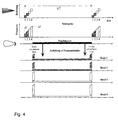
- the time sequence is in a direction-time diagram and one Frequency-time diagram shown.
- the K single pulses are consecutive radiated in the K adjacent directions.
- the history the instantaneous frequency shows the individual chirps.
- the process is after the Time ⁇ T repeated. In between, the receiving gate can for a period of time ⁇ T - K ⁇ t be opened.
- the processes shown below after receipt refer to the next step.
- the digital data is then saved. Subsequently they become a Fourier transform subjected along the distance axis.
- the echoes of each Transmit pulses are now collected in non-overlapping frequency bands and can be separated with it (see Figure 4).
- Pulse compression means filtering with the matched filter or a modified filter ( mismatched filter ).
- the convolution with the filter pulse response in the frequency domain can be replaced by a multiplication with the transfer function. Since the data after the Fourier transformation is already available in the frequency domain, only the multiplication by the transfer function of the filter (reference function) and the backward transformation into the time domain are missing for pulse compression.
- the separation into the individual frequency bands can now be done during the pulse compression by multiplying by the respective reference function, which is yes the corresponding frequency bands are concentrated and in the rest of the range can be set to zero.
- the transformation back into the time domain is finally done by using the inverse FFT.
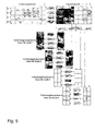
- Figure 5 shows this process. It should be noted that the sampling for the entire frequency range (K ⁇ f) produces K times the number of samples how to cover the distance range with a resolution corresponding to the Bandwidth ⁇ f required according to the Nyquist criterion. After the Fourier transformation the frequency range can therefore be broken down into K sections (field above right), the number of values of which corresponds to the original requirement. The following operations (Multiplication with the reference function, inverse transformation) can with a number reduced by a factor of K. All operations have been done separately in parallel for the K reception channels. It should be noted that the separation in the frequency domain also separates the directions occurred because each transmission lobe was assigned a specific frequency.
- the distance compression obtained in this way is compressed over several pulses Data collected and separately subjected to STAP processing.
- the process is shown in Figure 6 for clarity.
- the flow of the STAP processing is detailed in the appendix.
- the reference signals are to the respective Club directions and adapted to a number of predetermined Doppler frequencies.
- the transmission lobes are not directly one after the other, but in a changing order or nested Posted.
- a non-equidistant pulse-to-pulse scan can be used for the radar period bring about what can resolve the Doppler ambiguity.
- Another advantage is the recovery time for the transmit / receive modules after sending a pulse.
- boundary conditions relating to the method according to the invention are set out below are presented in more detail and quantified. Under a) of the boundary conditions for a conventional scan MIT system with STAP processing went out. Furthermore, the time required for a predefined area calculated using the conventional method. Subsequently under b) the time conditions for the method according to the invention and for the same task as under a) the MTI performance of the method according to the invention specified.
- a duty cycle of duty ⁇ t / ⁇ T is achieved.
- the echoes point to fixed targets Doppler shift, which is proportional to the respective radial component the relative speed. This depends on the angle to the movement axis, so that the points of equal Doppler shift on the mantle of a Cone, the axis of which is in the direction of flight.
- the totality of the ground echoes is thus characterized as expanded in the Doppler range Clutter spectrum from, whose shape by the two-way characteristic of the antenna is determined.
- the Doppler frequency of slowly moving targets is usually within of the main lobe portion of the clutter spectrum, so that a separation alone via the Doppler frequency is not possible as with ground-based radars.
- the STAP procedure can help: If several subapertures are used, the lengthways are offset in the direction of flight, the wave field reflected by the ground sampled at different times through the individual sub-apertures, the signals in the individual Ideally, channels only differ in this time offset. Moving However, targets with a radial velocity component change within it Time period their distance from the sensor so that the signals undergo a phase shift and can be distinguished from the cluster signals.
- the samples of the K subapertures are combined over a number N P of pulses to form a K * N P - dimensional space-time vector W.
- High correlations between samples of different subapertures at different pulses mean that an application of the inverse covariance matrix to space-time vectors is able to suppress clutter echoes.
- the signal of a moving target from a certain direction ⁇ with a certain Doppler frequency F can also be modeled in space-time notation as a complex K * N P -dimensional vector s ( ⁇ , F).
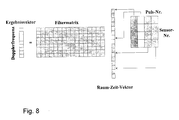
- a suitable technical implementation for unknown Doppler frequency is the construction of an M x K * N P filter matrix for M different Doppler frequencies and the line of sight ⁇ 0
- Figure 8 shows the arrangement of the data in a space-time vector and the application of the filter matrix described above. The result is to be handled like the result of an ordinary Doppler filter bank.
- the samples can be taken from the various distance cells.
Landscapes
- Engineering & Computer Science (AREA)
- Radar, Positioning & Navigation (AREA)
- Remote Sensing (AREA)
- Computer Networks & Wireless Communication (AREA)
- Physics & Mathematics (AREA)
- General Physics & Mathematics (AREA)
- Radar Systems Or Details Thereof (AREA)
Abstract
Description
- Fig. 1
- einen schematisierten Suchbereich für ein MTI-Radar,
- Fig. 2
- den Sendevorgang für K Keulen bei K Frequenzbändern,
- Fig. 3
- die Keulenbildung während des Empfangs,
- Fig. 4
- eine zeitliche Abfolge des Sendebetriebes,
- Fig. 5
- den ersten Schritt der Verarbeitung der empfangenen Signale,
- Fig. 6
- die STAP-Verarbeitung eines Entfernungsringes für eine Keule,
- Fig. 7
- die zeitlichen Bedingungen für entfernungseindeutige Abtastung beim STAP-Verfahren,
- Fig. 8
- die Raum-Zeit-Filterung gemäß STAP-Verfahren.
- Die Gruppenantenne muss sendeseitig für eine Momentanbandbreite Δf und eine Gesamt-Bandbreite KΔf ausgelegt sein. Die Momentanbandbreite wird durch die Anforderung an Entfernungsauflösung bestimmt. So ist für eine übliche Auflösung von 15 Metern eine Bandbreite von etwa 10 MHz erforderlich, so dass mit K=4 die Gesamtbandbreite etwa 40 MHz beträgt. Dieser Wert stellt für eine moderne Gruppenantenne keine besondere Schwierigkeit dar.
- Die Sende-Empfangs-Module müssen in der Lage sein, K Sendepulse der Länge Δt unmittelbar hintereinander bei verschiedenen Mittenfrequenzen an die Strahlerelemente abzugeben und zwischen den Pulsen die Senderichtung durch Betätigung der Phasenschieber umzuschalten. Während der üblichen Umschaltzeit der Phasenschieber von etwa 20 - 50 nsec ist eine entsprechende Pause zwischen den Einzelpulsen erlaubt.
- Die Gruppenantenne muss mit K parallelen Empfangskanälen ausgerüstet sein, die an K aneinanderstoßende Subaperturen angeschlossen sind. Eine solche Anordnung ist üblich, wenn mit der Antenne eine Entdeckung auch langsam bewegter Bodenfahrzeuge durchgeführt werden soll.
- Die Empfangsbandbreite muss mindestens gleich KΔf sein. Wie oben erläutert, stellt dies für realistische Parameterannahmen kein Problem dar.
- Die Empfangssignale müssen mit einer Frequenz von mindestens KΔf abgetastet werden. Auch diese Forderung ist nach dem Stand der Technik ohne weiteres realisierbar.
| Radarparameter und ihre Beziehungen | |
| Wellenlänge | λ |
| Winkelbereich | ϕmin bis ϕmax |
| Entfernungsbereich | Rmin bis Rmax |
| Abgedeckte Fläche | A = ½(ϕmax-ϕmin)×(R2 max-R2 min) |
| Abtastraster im Winkelbereich | Δϕ |
| Anzahl Suchrichtungen | Nϕ = (ϕmax-ϕmin)/Δϕ |
| Anzahl Pulse pro Richtung | Np |
| Pulswiederholintervall | ΔT |
| Pulswiederholfrequenz | PRF = 1/ΔT |
| Zeitbedarf zur Überdeckung des Suchbereichs | Tges = Nϕ× Np× ΔT |
| Pulslänge | Δt |
| Bandbreite des Einzelpulses | Δf |
| Eindeutig erfassbare Zielgeschwindigkeit | Vmax = λ/(4ΔT) |
| Zeit der Zielbeleuchtung | tges = Np× Δt |
| Trägergeschwindigkeit | v |
| Zurückgelegter Weg während eines Pulszuges | L = v × (Np-1) × ΔT |
| Antennenlänge | 1 |
| Keulenbreite bei voller Ausnutzung der | δϕ = λ/1 |
| Antennenlänge | |
| Dutycycle | duty = Δt/ΔT |


Eine geeignete technische Realisierung für unbekannte Dopplerfrequenz ist der Aufbau einer M x K*NP Filtermatrix


Claims (4)
- Verfahren für ein multiples RADAR, bei dem in direkter Abfolge K Sendekeulen mit verschiedenen Mittenfrequenzen in verschiedene Richtungen abgestrahlt werden, deren Echos in einer nachfolgenden Empfangsphase mit K Subaperturen empfangen und für jede Subapertur in zugeordneten Empfangskanälen aufbereitet und ausgewertet wird,
gekennzeichnet durch die Verfahrensschritte:a) die Auswahl einer ersten Sendekeulenrichtung ϕ1 und das Festlegen der Sendeparameter,b) Aussenden eines Pulses bestimmter Länge Δt und der Bandbreite Δf, bei einer Mittenfrequenz f1,c) Einstellen einer nächsten Sendekeulenrichtung ϕ2 = ϕ1 + Δϕ und weiterer Sendekeulenrichtungen,d) Aussenden des nächsten Pulses und weiterer Pulse bis zur K-ten Richtung, mit den jeweils Verfahrensschritt b) entsprechenden Parametern,e) Fokussierung der Antennenelemente auf den Mittelwert der Senderichtungen,f) Einschalten eines Empfängerarrays mit K Empfangselementen, dessen Empfangsbandbreite und Abtastrate mindestens KΔf aufweist, wobei die Empfangskeulenbreite jeder Subapertur KΔϕ beträgt,g) digitale Aufbereitung und Speicherung der empfangenen Daten,h) die nachfolgend einer Fouriertransformation längs der Entfernungsachse unterzogen werden, so dass die Echos der einzelnen Sendepulse in nicht überlappenden Frequenzbändern gesammelt, während einer Pulskompression durch Multiplikation mit der jeweiligen Referenzfunktion, die auf die entsprechenden Frequenzbänder konzentriert sind, und der Anwendung einer inversen FFT, voneinander trennbar vorliegen,i) die so erhaltenen entfernungskomprimierten Daten über mehrere Pulse hinweg gesammelt, separat einer Raum-Zeit-Verarbeitung unterzogen werden. - Verfahren nach Anspruch 1,
dadurch gekennzeichnet, dass die Reihenfolge der ausgesendeten Sendekeulen so wechselt, dass für jedes einzelne Richtung-Frequenzpaar die Pulswiederholintervalle nicht mehr äquidistant sind. - Verfahren nach Anspruch 1,
dadurch gekennzeichnet, dass die Sendekeulen verschachtelt gesendet werden und die entstehenden Lücken im Empfangsbereich durch Aussendung weiterer Pulszüge mit anderen Pulswiederholfrequenzen geschlossen werden. - Einrichtung zur Durchführung des Verfahrens nach einem der Ansprüche 1 bis 3, mit einem Generator für mehrere unterschiedliche, in Folge erzeugte Hochfrequenzsignale, einer Sendeantenne mit mehreren Anschlüssen und Empfangseinrichtungen mit einer angeschlossenen Signalverarbeitung,
gekennzeichnet durch,
eine phasengesteuerte Gruppenantenne, die Sende-Empfangs-Module aufweist, die in der Lage sind, K-Sendepulse der Länge Δt unmittelbar hintereinander bei verschiedenen Mittenfrequenzen an die Strahlerelemente abzugeben und zwischen den Pulsen die Senderichtung umzuschalten, wobei die Antenne mit K parallelen Empfangskanälen ausgerüstet ist, die an K aneinanderstoßende Subaperturen angeschlossen sind und die zur Signalverarbeitung entsprechend des Verfahrens nach einem der Ansprüche 1 bis 3 eingerichtet sind.
Priority Applications (2)
| Application Number | Priority Date | Filing Date | Title |
|---|---|---|---|
| EP20000116587 EP1178332B1 (de) | 2000-08-01 | 2000-08-01 | Verfahren und Einrichtung für ein multiples Radar |
| DE50015678T DE50015678D1 (de) | 2000-08-01 | 2000-08-01 | Verfahren und Einrichtung für ein multiples Radar |
Applications Claiming Priority (1)
| Application Number | Priority Date | Filing Date | Title |
|---|---|---|---|
| EP20000116587 EP1178332B1 (de) | 2000-08-01 | 2000-08-01 | Verfahren und Einrichtung für ein multiples Radar |
Publications (2)
| Publication Number | Publication Date |
|---|---|
| EP1178332A1 true EP1178332A1 (de) | 2002-02-06 |
| EP1178332B1 EP1178332B1 (de) | 2009-07-01 |
Family
ID=8169414
Family Applications (1)
| Application Number | Title | Priority Date | Filing Date |
|---|---|---|---|
| EP20000116587 Expired - Lifetime EP1178332B1 (de) | 2000-08-01 | 2000-08-01 | Verfahren und Einrichtung für ein multiples Radar |
Country Status (2)
| Country | Link |
|---|---|
| EP (1) | EP1178332B1 (de) |
| DE (1) | DE50015678D1 (de) |
Cited By (1)
| Publication number | Priority date | Publication date | Assignee | Title |
|---|---|---|---|---|
| DE102005007917A1 (de) * | 2004-12-20 | 2006-06-22 | Valeo Schalter Und Sensoren Gmbh | Kraftfahrzeug-Radarsystem und Auswerteverfahren |
Citations (2)
| Publication number | Priority date | Publication date | Assignee | Title |
|---|---|---|---|---|
| EP0132378B1 (de) * | 1983-07-21 | 1990-01-31 | Nec Corporation | Mehrkeulenabtastradarsystem |
| DE19906149A1 (de) * | 1999-02-13 | 2000-09-07 | Forschungsgesellschaft Fuer An | Verfahren und Vorrichtung zur Steigerung der Bewegtziel-Entdeckungs-Leistung eines bewegten Phased-Array-Radars mit mehreren Empfangskanälen |
-
2000
- 2000-08-01 DE DE50015678T patent/DE50015678D1/de not_active Expired - Lifetime
- 2000-08-01 EP EP20000116587 patent/EP1178332B1/de not_active Expired - Lifetime
Patent Citations (2)
| Publication number | Priority date | Publication date | Assignee | Title |
|---|---|---|---|---|
| EP0132378B1 (de) * | 1983-07-21 | 1990-01-31 | Nec Corporation | Mehrkeulenabtastradarsystem |
| DE19906149A1 (de) * | 1999-02-13 | 2000-09-07 | Forschungsgesellschaft Fuer An | Verfahren und Vorrichtung zur Steigerung der Bewegtziel-Entdeckungs-Leistung eines bewegten Phased-Array-Radars mit mehreren Empfangskanälen |
Non-Patent Citations (1)
| Title |
|---|
| KLEMM R ET AL: "TWO-DIMENSIONAL FILTERS FOR RADAR AND SONAR APPLICATIONS", PROCEEDINGS OF THE EUROPEAN SIGNAL PROCESSING CONFERENCE,NL,AMSTERDAM, ELSEVIER, vol. CONF. 5, 18 September 1990 (1990-09-18), pages 2023 - 2026, XP000365956 * |
Cited By (1)
| Publication number | Priority date | Publication date | Assignee | Title |
|---|---|---|---|---|
| DE102005007917A1 (de) * | 2004-12-20 | 2006-06-22 | Valeo Schalter Und Sensoren Gmbh | Kraftfahrzeug-Radarsystem und Auswerteverfahren |
Also Published As
| Publication number | Publication date |
|---|---|
| DE50015678D1 (de) | 2009-08-13 |
| EP1178332B1 (de) | 2009-07-01 |
Similar Documents
| Publication | Publication Date | Title |
|---|---|---|
| EP2018577B1 (de) | Hochauflösendes synthetik-apertur-seitensicht-radarsystem mittels digital beamforming | |
| DE60117065T2 (de) | Seitensichtradarsystem mit synthetischer Apertur | |
| DE102007041373B3 (de) | Synthetik-Apertur-Radarverfahren | |
| JP6437925B2 (ja) | 多スワスストリップマップsarイメージング | |
| EP2725382B1 (de) | Synthetisches Apertur Radar zur gleichzeitigen Bildaufnahme und Bewegtzielerkennung | |
| DE102005062031B4 (de) | Hochauflösende Synthetik-Apertur-Radarvorrichtung | |
| EP2753950B1 (de) | Abbildender radarsensor mit synthetischer vergrösserung der antennenapertur und zweidimensionaler strahlschwenkung | |
| EP2353029B1 (de) | Vorrichtung zum empfang von sekundärradarsignalen mit quasi dynamischer oder dynamischer sektorisierung des zu überwachenden raumes und verfahren hierzu | |
| EP1588190A1 (de) | Winkelauflösendes antennensystem | |
| DE4244001A1 (de) | ||
| DE102008054228A1 (de) | Fahrzeugseitige Richtungserkennungsvorrichtung zur genauen Erkennung von Zielkörperrichtungen ungeachtet der Fahrgeschwindigkeit | |
| DE112005003673B4 (de) | Zielerfassungsverfahren und Zielerfassungsvorrichtung | |
| EP1065518B1 (de) | Hochauflösendes Synthetik-Apertur-Radarsystem | |
| DE3731036A1 (de) | Radar mit großem Augenblicks-Feldwinkel und hohem Augenblicks-Winkelauflösungsvermögen, insbesondere für ein Flugkörper-Zielsuchgerät | |
| EP0487940B1 (de) | Pulsdoppler-Radargerät | |
| EP2722686B1 (de) | Interferometrisches sar-system | |
| DE19906149B4 (de) | Radarverfahren für ein luft- oder raumgestütztes Radar | |
| EP1178332B1 (de) | Verfahren und Einrichtung für ein multiples Radar | |
| DE102019219649A1 (de) | Kooperatives Radarsensorsystem mit winkelauflösenden Radarsensoren | |
| WO2009077236A1 (de) | Monostatischer mehrstrahl-radarsensor, sowie verfahren | |
| DE10057564A1 (de) | Ansteuernetzwerk für eine Antennenanordnung eines Radarsensors, Radarantenne und Radarsensor | |
| DE602004004853T2 (de) | Radar mit synthetischen Peilkanälen | |
| DE102005022028B4 (de) | Hochauflösendes Synthetik-Apertur-Seitensicht-Radarsystem | |
| DE102018206670B3 (de) | Synthetik-Apertur-Radarverfahren zur Fernerkundung der Erdoberfläche und Synthetik-Apertur-Radarvorrichtung | |
| DE102023200997A1 (de) | Verfahren zur Objektdetektion und winkelauflösendes FMCW-Radarsensorsystem |
Legal Events
| Date | Code | Title | Description |
|---|---|---|---|
| PUAI | Public reference made under article 153(3) epc to a published international application that has entered the european phase |
Free format text: ORIGINAL CODE: 0009012 |
|
| AK | Designated contracting states |
Kind code of ref document: A1 Designated state(s): AT BE CH CY DE DK ES FI FR GB GR IE IT LI LU MC NL PT SE Kind code of ref document: A1 Designated state(s): DE FR GB IT |
|
| AX | Request for extension of the european patent |
Free format text: AL;LT;LV;MK;RO;SI |
|
| 17P | Request for examination filed |
Effective date: 20020606 |
|
| AKX | Designation fees paid |
Free format text: DE FR GB IT |
|
| RAP1 | Party data changed (applicant data changed or rights of an application transferred) |
Owner name: EADS DEUTSCHLAND GMBH |
|
| GRAP | Despatch of communication of intention to grant a patent |
Free format text: ORIGINAL CODE: EPIDOSNIGR1 |
|
| GRAP | Despatch of communication of intention to grant a patent |
Free format text: ORIGINAL CODE: EPIDOSNIGR1 |
|
| GRAS | Grant fee paid |
Free format text: ORIGINAL CODE: EPIDOSNIGR3 |
|
| GRAA | (expected) grant |
Free format text: ORIGINAL CODE: 0009210 |
|
| AK | Designated contracting states |
Kind code of ref document: B1 Designated state(s): DE FR GB IT |
|
| REG | Reference to a national code |
Ref country code: GB Ref legal event code: FG4D Free format text: NOT ENGLISH |
|
| REF | Corresponds to: |
Ref document number: 50015678 Country of ref document: DE Date of ref document: 20090813 Kind code of ref document: P |
|
| PLBE | No opposition filed within time limit |
Free format text: ORIGINAL CODE: 0009261 |
|
| STAA | Information on the status of an ep patent application or granted ep patent |
Free format text: STATUS: NO OPPOSITION FILED WITHIN TIME LIMIT |
|
| 26N | No opposition filed |
Effective date: 20100406 |
|
| REG | Reference to a national code |
Ref country code: DE Ref legal event code: R081 Ref document number: 50015678 Country of ref document: DE Owner name: AIRBUS DEFENCE AND SPACE GMBH, DE Free format text: FORMER OWNER: EADS DEUTSCHLAND GMBH, 85521 OTTOBRUNN, DE Effective date: 20140916 |
|
| REG | Reference to a national code |
Ref country code: FR Ref legal event code: PLFP Year of fee payment: 16 |
|
| PGFP | Annual fee paid to national office [announced via postgrant information from national office to epo] |
Ref country code: DE Payment date: 20150821 Year of fee payment: 16 Ref country code: GB Payment date: 20150819 Year of fee payment: 16 |
|
| PGFP | Annual fee paid to national office [announced via postgrant information from national office to epo] |
Ref country code: FR Payment date: 20150820 Year of fee payment: 16 |
|
| PGFP | Annual fee paid to national office [announced via postgrant information from national office to epo] |
Ref country code: IT Payment date: 20150824 Year of fee payment: 16 |
|
| REG | Reference to a national code |
Ref country code: DE Ref legal event code: R119 Ref document number: 50015678 Country of ref document: DE |
|
| GBPC | Gb: european patent ceased through non-payment of renewal fee |
Effective date: 20160801 |
|
| REG | Reference to a national code |
Ref country code: FR Ref legal event code: ST Effective date: 20170428 |
|
| PG25 | Lapsed in a contracting state [announced via postgrant information from national office to epo] |
Ref country code: FR Free format text: LAPSE BECAUSE OF NON-PAYMENT OF DUE FEES Effective date: 20160831 Ref country code: GB Free format text: LAPSE BECAUSE OF NON-PAYMENT OF DUE FEES Effective date: 20160801 Ref country code: DE Free format text: LAPSE BECAUSE OF NON-PAYMENT OF DUE FEES Effective date: 20170301 |
|
| PG25 | Lapsed in a contracting state [announced via postgrant information from national office to epo] |
Ref country code: IT Free format text: LAPSE BECAUSE OF NON-PAYMENT OF DUE FEES Effective date: 20160801 |