EP1175108A2 - Verfahren zur Überprüfung von Bildwiedergabegeräten und Computerprogramm dazu sowie Verfahren zum Betrieb von medizinischen Geräten - Google Patents
Verfahren zur Überprüfung von Bildwiedergabegeräten und Computerprogramm dazu sowie Verfahren zum Betrieb von medizinischen Geräten Download PDFInfo
- Publication number
- EP1175108A2 EP1175108A2 EP01115033A EP01115033A EP1175108A2 EP 1175108 A2 EP1175108 A2 EP 1175108A2 EP 01115033 A EP01115033 A EP 01115033A EP 01115033 A EP01115033 A EP 01115033A EP 1175108 A2 EP1175108 A2 EP 1175108A2
- Authority
- EP
- European Patent Office
- Prior art keywords
- image
- parameter
- test
- contrast
- image parameter
- Prior art date
- Legal status (The legal status is an assumption and is not a legal conclusion. Google has not performed a legal analysis and makes no representation as to the accuracy of the status listed.)
- Withdrawn
Links
Images


Classifications
-
- G—PHYSICS
- G01—MEASURING; TESTING
- G01N—INVESTIGATING OR ANALYSING MATERIALS BY DETERMINING THEIR CHEMICAL OR PHYSICAL PROPERTIES
- G01N23/00—Investigating or analysing materials by the use of wave or particle radiation, e.g. X-rays or neutrons, not covered by groups G01N3/00 – G01N17/00, G01N21/00 or G01N22/00
- G01N23/02—Investigating or analysing materials by the use of wave or particle radiation, e.g. X-rays or neutrons, not covered by groups G01N3/00 – G01N17/00, G01N21/00 or G01N22/00 by transmitting the radiation through the material
- G01N23/04—Investigating or analysing materials by the use of wave or particle radiation, e.g. X-rays or neutrons, not covered by groups G01N3/00 – G01N17/00, G01N21/00 or G01N22/00 by transmitting the radiation through the material and forming images of the material
-
- G—PHYSICS
- G06—COMPUTING OR CALCULATING; COUNTING
- G06T—IMAGE DATA PROCESSING OR GENERATION, IN GENERAL
- G06T7/00—Image analysis
- G06T7/0002—Inspection of images, e.g. flaw detection
-
- G—PHYSICS
- G06—COMPUTING OR CALCULATING; COUNTING
- G06T—IMAGE DATA PROCESSING OR GENERATION, IN GENERAL
- G06T7/00—Image analysis
- G06T7/0002—Inspection of images, e.g. flaw detection
- G06T7/0004—Industrial image inspection
- G06T7/001—Industrial image inspection using an image reference approach
-
- H—ELECTRICITY
- H04—ELECTRIC COMMUNICATION TECHNIQUE
- H04N—PICTORIAL COMMUNICATION, e.g. TELEVISION
- H04N17/00—Diagnosis, testing or measuring for television systems or their details
-
- G—PHYSICS
- G06—COMPUTING OR CALCULATING; COUNTING
- G06T—IMAGE DATA PROCESSING OR GENERATION, IN GENERAL
- G06T2207/00—Indexing scheme for image analysis or image enhancement
- G06T2207/30—Subject of image; Context of image processing
- G06T2207/30004—Biomedical image processing
-
- H—ELECTRICITY
- H04—ELECTRIC COMMUNICATION TECHNIQUE
- H04N—PICTORIAL COMMUNICATION, e.g. TELEVISION
- H04N5/00—Details of television systems
- H04N5/44—Receiver circuitry for the reception of television signals according to analogue transmission standards
- H04N5/57—Control of contrast or brightness
-
- H—ELECTRICITY
- H04—ELECTRIC COMMUNICATION TECHNIQUE
- H04N—PICTORIAL COMMUNICATION, e.g. TELEVISION
- H04N5/00—Details of television systems
- H04N5/44—Receiver circuitry for the reception of television signals according to analogue transmission standards
- H04N5/57—Control of contrast or brightness
- H04N5/58—Control of contrast or brightness in dependence upon ambient light
Definitions
- the invention relates to a method for checking of image display devices, in particular in medical Diagnostics and a computer program for this as well a method of operating medical devices.
- the image display device is part of a device for performing computed tomography, ultrasound or x-rays such as mammograms or dental panoramas, one in one Have stored digital image.
- This digital image must be viewed by the user be made accessible for what it is on an image display device is pictured.
- the quality of the presentation of the digital image on the image display device depends largely on the ambient lighting depending on the specific settings of the Image display device itself. It also affects also the generation of the image signal from the as Digital image data stored using pixel values a graphics card and the transformation characteristic for the assignment of pixel values to color values the quality the representation.
- light density measurement methods are used where with a sensor the light density of the switched off image display device and the light density one of the brightest points of the image display device is measured and a setting based on the measured values of the image display device in terms of brightness and Contrast occurs.
- This setting must not be used again be changed and the environmental conditions that occur during basically have to have the measurement during the entire operation of the image display device maintained for diagnostic purposes. In As a rule, corresponding darkening of the room required in which the image display device is installed is.
- an image parameter such as Contrast, resolution, noise
- the image parameter of the partial area By comparing the image parameter of the partial area with the image parameter of the rest of the test field, for example a surrounding area, can be a parameter derive, which allows a statement about whether the quality the image reproduction the diagnostic requirements equivalent. This also allows changing environmental conditions and even changed settings on Determine image display device and on the suitability of the Playback device for medical diagnosis check.
- the dynamic change of the sub-areas the test field and the time of perception of Is a measure of change Playback quality of the system including the current lighting situation and physiological Constitution, especially the adaptation of the eye of the Evaluator.
- the low contrast elements are 95% and 5% of the test image are used as test fields and dynamic be changed, because in these fields already changed Areas exist.
- test fields are advantageously spaced apart and can can be queried one after the other. This is particularly useful then when a test field is bright and a test field is dark to saturate the eye by the alternating focus on a dark or light Prevent area.
- the test field is advantageously in the initial state in the playback-specific problem area of Image parameters so that a measurement is already a statement about the quality of the image reproduction.
- these can be Initial state in the opposite end area of the image parameter. It goes without saying itself that in the areas of the image parameter, in who are normally not expected to have any problems it is generally not necessary to carry out measurements is.
- the illuminance on the image display device detected.
- This has the advantage that the so captured Illuminance with the illuminance during the medical diagnosis of the on the display device compared image and if the image is too large Variations in illuminance at the risk of Misdiagnosis can be pointed out. Can continue certain sub-functions of the system are blocked, for example, under these conditions, the display of the picture. With the additional capture The illuminance becomes a high level of operational reliability reached.
- the partial area and the surrounding area advantageously have homogeneous image parameters over their respective surface so that a flat impression is created and a better comparison of the image values is possible.
- the contrast is advantageously used as the image parameter and / or the resolution and / or the noise is used, preferably using a black and white image becomes.
- the contrast of other colors can also be used.
- the method can be used in the Area where certain contrast differences are not can be recognized, none or correspondingly fewer Contrast values are used to display the digital image become. This makes it possible to use the evaluation option of digital images even with reduced To improve the quality of the image display device, however, care must be taken that a minimum quality is available.
- the illuminance can be determined at the time of the determination the behavior of the playback device with respect an image parameter with the illuminance for Time of actual use of the medical Device are compared and at a predetermined Deviations beyond the tolerance range can the functional processes are controlled depending on the parameter become.
- Another object of the invention is a method for Playback of image data on image display devices in medical diagnostics, in which the illuminance at the time of checking with illuminance compared at the time of actual use is, only if within a predetermined Deviations within a tolerance range are reproduced the image data takes place on the image display device.
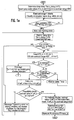
- 1, 1a and 1b is a program flow chart for Execution of the method according to the invention on a reproduced not shown calculator.
- the method is in a digital memory stored test image, when displaying the digital image pixels converted into analog video signals or in corresponding digital image reproduction signals in digital display devices such as flat screens. Using these video signals or digital Image reproduction signals are displayed on the Image display device and can be there by the user to be viewed as.
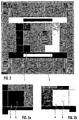
- the test image shown in FIG. 2, has different ones Contrast areas, two of which are in contrast changeable test fields 1,2 are.
- Each of the test fields 1, 2 consists of a surrounding area 3, 4 with a gray value K1a or K2a and one completely embedded in the surrounding area 3, 4 Subarea 5.6 with a gray value K1i or K2i.
- test field 1 the gray values are shown at the beginning 0, which corresponds to a complete darkness, in test field 2, the gray values become 255 determines what corresponds to a white area.
- the test fields 1, 2 are therefore initially shown completely uniform.
- Gray values defined for the data initialization for Test fields 1 and 2 are also read in and on the Display devices shown.
- the section 5.6 of the test field 1,2 in which the changes are expected are indicated by a mark 7 in the form of a dashed line Line highlighted.
- the contrast value K1 is after the Pressing the Enter key calculates, saves and in is displayed in a status field.
- the contrast value K2 becomes from the then available data calculated, saved and displayed in the status field.
- the gray value is reinitialized K2a made in which the identified, recognized Gray value K2i of subarea 6 also the surrounding area 4 is assigned with the gray value K2a.
- FIG. 2 an SMPTE test pattern is shown, which consists of there are many different areas. Amongst other things are fields with different contrasts of 0, 10, 20, .... up to 100% are provided, beyond that in the middle and the corners of the grids are different Line density provided. Are of importance here two test fields 1,2 different in the field of fields Contrast.
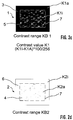
- the test fields 1, 2 are shown in FIGS. 2a and 2b in detail and in FIGS. 2c and 2d schematically shown.
- the test field 1 from FIG. 2a consists from a surrounding area 3, into which a partial area 5 is completely embedded, with partial area 5 being a has higher contrast than the surrounding area 3, the gray scale value of subarea 5 is higher than that Gray value of the surrounding area 3.
- the registered Measured values were formed so that the number the required gait level values until they are determined the next level of contrast was found, this is thus the difference between the value K1a and the value K1i, where the number of gray levels determined by divided the total available grayscale number of 256 and multiplied by 100 by a percentage to obtain.
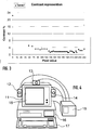
- the image display device actually offers instead of 256 gray values only 39 distinguishable Gray values. Since the digital image data on 256 gray values distributed, a correction of the gray values of the Image data take place in such a way that the 256 gray values can be converted to 39 in order to minimize Avoid loss of information. With this correction the range of the gray values to be displayed can then be enlarged if the digital image data is not exhaust the full range of 256 gray values, but for example, have only 100 different gray values. In this case the resolution is 256/39 increased to 150/39.
- Advantageously only Gray values in the marginal area are not taken into account not to falsify the characteristic of the image data.
- the 4 is a device structure for performing the Procedure illustrated. They can be recognized by an image display device 11 arranged sensors 12-14 for determination the illuminance of the environment during the implementation of the procedure and also later during operation of the image display device 11.
- the sensors 12-14 are connected to a computer via a connection device 15 16 connected to which a keyboard 17 and a Screen 18 are connected. On screen 18 the image is displayed in the company that relates to the medical Diagnosis pending.
- 1 further shows that in the program area, in which the gray values of the partial area 3.4 are increased and must be assessed by the viewer, a Taking into account the response time in which assumed an average response time when entering and is calculated back to the value that the recognized Value corresponds to K1eff. So the user recognizes a contrast difference, so a reaction time passes until you press the enter key with which the program is informed that the contrast change was recognized. During this time, the contrast of the partial area, however, increased further, so that the gray value then determined is higher than that actually already recognized value. Then will the effectively recognized value is displayed in the test field.
- the method according to the invention can, for example, be regular after switching on the monitor or any other, predetermined Point in time, for example after the screen has warmed up, for information about the quality of the Get image reproduction.
- the influence of ambient lighting be detected by a sensor and then at the medical diagnosis of the on the display device to allow an image to be checked.
- the brightness itself not directly determined.
- the grayscale is then not determined can when the brightness of the image display device is not big enough, which among other things depends on the illuminance of the environment.
- Performance characteristics of the image display device are determined failing to achieve medical functions Diagnosis restricted, blocked or only after confirmation by the user. there can in particular reject a representation of images or an input of results into the computer be locked. Will the procedure before creating of the recording providing the digital image data, so if certain performance characteristics are not achieved blocked the creation of the recording become. This avoids that of a faulty one System is working, which is not sufficient allows medical diagnosis.
- the degree of restriction is based on the barely recognizable contrast K1 and K2, which according to the diagram from FIG. 1 was determined, the ambient illuminance ET0 at the time of measurement, the technology and modality of image acquisition to Example ultrasound, CT, mammography, dental, medical Indication, for example diagnosis, control, in the dental field root canal treatment, caries detection, the ambient illuminance the ETN at Time of use of the playback system. Thanks to the Equidistant contrast values can be obtained using the procedure entire brightness range can be determined. In order to characteristics for improving the display quality by compensating for non-ideal display properties determine the playback device.
- the method therefore has a light density measuring method the advantage that the image playback chain is taken into account, namely the digital value of the Test image or test pattern, implementation in video signal via the graphics card, the graphics mode, the software, the cables, representation on the display device with a certain illuminance and a characteristic under conditions of ambient lighting and constitution of the viewer.
- the process can be carried out at two essential points Contribute quality management by the identified Process results to demonstrate the applied system and process quality can be documented.
- Documentation can be part of the legible report and thus be part of the finding, but also in the data record of the diagnosis text or the diagnosis Image.
- the image parameters are the contrast, the Spatial resolution, the noise and combinations thereof.
- Local resolutions can be arranged side by side Lines are determined.
- the differ Lines high contrast from each other, e.g. black-and-white or 0/255.
- the parameter for resolution could be the number of line pairs per length.
- the dynamic Element then results from the continuous reduction of line pairs per length.
- the noise requires an arrangement similar to that of Contrast.
- the mean gray or color value remains constant, the distribution of the values will change.
- an individual Characteristic curve of the image display device can be determined depending on the current settings and the illuminance. If the characteristic is known, compensation can take place by transforming the characteristic so that it specifies essentially equidistant contrast values, that are just recognized in a special case (Just noticeable differences - JND). Ideally, that should Number of grayscale or color contrast levels to be displayed Pixel values less than or equal to the JND number his.
- Each JND (n) can have an area n in the reproduction characteristic occupy.
- the pixel values are shown in the assignment table assigned to these areas. If more pixel values if there are JNDs, they must be merged. Ideally, the image impression through nonlinear Avoid falsifying the image if possible an average merger.
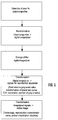
- FIG. 5 shows a flowchart for the higher-level process shown in the that described in Fig. 1 Procedure is embedded.
- the suitable one Method for example x-ray or ultrasound
- the object properties captured with a suitable sensor and converted into a digital one Image made up of pixels is transformed.
- the resulting digital image data will be stored.
- To prepare the display of digital Image data must be converted into signals for a playback device be transformed.
- variable description Type value range k 1a Gray value in contrast area KB1 - outside 0-255 K1i Gray value in contrast area KB1 - inside 0-255 K 2 Gray value in contrast area KB2 - outside 0-255 K2i Gray value in contrast area KB2 - inside 0-255 n nth incremental loop in KB1 m mth incremental loop in KB2 k kth pass through KB1 and KB2 K1_k contrast value determined from area KB1 for the k-th pass 0.1 - 10% K2_k
- the variables are from the outside through the program flow determined, the constants are not from the outside over the Program flow changeable values, but are through Initialization, algorithms or program implementation specified.
Landscapes
- Engineering & Computer Science (AREA)
- Physics & Mathematics (AREA)
- General Physics & Mathematics (AREA)
- General Health & Medical Sciences (AREA)
- Quality & Reliability (AREA)
- Theoretical Computer Science (AREA)
- Health & Medical Sciences (AREA)
- Computer Vision & Pattern Recognition (AREA)
- Signal Processing (AREA)
- Multimedia (AREA)
- Biomedical Technology (AREA)
- Life Sciences & Earth Sciences (AREA)
- Chemical & Material Sciences (AREA)
- Analytical Chemistry (AREA)
- Biochemistry (AREA)
- Immunology (AREA)
- Pathology (AREA)
- Measuring And Recording Apparatus For Diagnosis (AREA)
Abstract
Description
- Fig. 1
- einen Programmablaufplan zur Ausführung des erfindungsgemäßen Verfahrens mit den Fig. 1a und 1b, die
- Fig. 2
- ein Testbild mit zwei Testfeldern, die in den Fig. 2a und 2b im Detail dargestellt sind,
- Fig. 3
- eine gemessene Kennlinie eines Bildwiedergabegerätes,
- Fig. 4
- eine Anordnung zur Durchführung des erfindungsgemäßen Verfahrens mit mehreren Sensoren zur Erfassung der Helligkeit und die
- Fig. 5
- einen Ablaufplan für das übergeordnete Verfahren, in das das in Fig. 1 beschriebene Verfahren eingebettet ist.
| Variable | Bezeichnung | Typ. Wertebereich |
| K1a | Grauwert in Kontrastbereich KB1 - aussen | 0-255 |
| K1i | Grauwert in Kontrastbereich KB1 - innen | 0-255 |
| K2a | Grauwert in Kontrastbereich KB2 - aussen | 0-255 |
| K2i | Grauwert in Kontrastbereich KB2 - innen | 0-255 |
| n | n-te Inkremental-Schleife in KB1 | |
| m | m-te Inkremental-Schleife in KB2 | |
| k | k-ter Durchlauf durch KB1 und KB2 | |
| K1_k | ermittelter Kontrastwert aus Bereich KB1 zum k-ten Durchlauf | 0,1 - 10% |
| K2_k | Ermittelter Kontrastwert aus Bereich KB2 zum k-ten Durchlauf | 0,1 - 10% |
| Emess_k | Mit Luxmeter gemessene Beleuchtungs-stärke am Monitor zum k-ten Durchlauf | 801x |
| Emess(k) | Vektor mit Emess_k | |
| Elimit (Funktion) | Vektor, berechnet aus K1_k, K2_k, E-mess_k, K1limit_reg und K2limit_reg, gibt an, welche Funktionen bei welcher max. Beleuchtungsstärke zugelassen sind | 2001x |
| Tenter | Zeitpunkt zu dem die ENTER-Taste ge-drückt wird | - |
| Teff | Effektiver Zeitpunkt zur Bestimmung Kontrastswert: Tenter minus Tuser_delay | - |
| K1eff_k | Berechneter Kontrast im Bereich KB1 zum Zeitpunkt Teff | |
| K1eff(k) | Vektor mit K1eff_k | |
| K2eff(k) | Vektor mit K2eff_k |
| Konstante | Bezeichnung | Typ. Wertebereich |
| Tloop_delay | per Zufall vom Programm bestimmte Verzögerungszeit (Z1 bzw. Z2) | 0 - 5 s |
| Tloop | Verzögerung (S) für In/Dekrement-Schleife | 0,1 - 2 s |
| Tuser_delay | zu beachtende Reaktionszeit des Anwenders | 0,1 - 2 |
| K1limit_reg | durch Richtlinien vorgegebener Mindestkontrast Bereich KB1 | 1% |
| K2limit_reg | durch Richtlinien vorgegebener Mindestkontrast Bereich KB2 | 1% |
Claims (18)
- Verfahren zur Überprüfung von Bildwiedergabeeinrichtungen, gekennzeichnet durch die Anordnung eines Testfeldes (1,2) als Teilbereich des dargestellten Bildes,Zuordnung eines Bildparameters (K1a, K1i) zu dem Testfeld (1,2);Veränderung eines Teilbereiches (5,6) des Testfeldes (1,2) bezüglich des Bildparameters (K1i);Erfassung einer Eingabe durch den Benutzer bei Erkennen eines Unterschiedes des Bildparameters zwischen dem Teilbereich (5,6) und dem restlichen Testfeld (1,2);Speichern des Bildparameters (K1i) des Teilbereichs (5,6);Vergleichen des Bildparameters (K1i) oder einer Transformation davon mit einem vorgegebenen Richtwert für den Bildparameter.
- Verfahren nach Anspruch 1, dadurch gekennzeichnet, daß das Testfeld (1,2) Bestandteil eines standardisierten Testbildes, insbesondere eines SMPTE-Testbildes ist.
- Verfahren nach Anspruch 2, dadurch gekennzeichnet, dass die Niedrigkontrastelemente 95 % und 5 % des Testbildes dynamisch verändert werden.
- Verfahren nach einem der Ansprüche 1 bis 3, dadurch gekennzeichnet, dass mindestens zwei Testfelder (1,2) abgefragt werden.
- Verfahren nach Anspruch 4, dadurch gekennzeichnet, dass das Testfeld (1,2) im Ausgangszustand im wiedergabespezifischen Problembereich des Bildparameters liegt.
- Verfahren nach einem der Ansprüche 1 bis 6, dadurch gekennzeichnet, dass die Veränderung des Bildparameters des Teilbereichs (5,6) zeitverzögert nach Auslösung des Testverfahrens erfolgt.
- Verfahren nach Anspruch 6, dadurch gekennzeichnet, dass die Zeitverzögerung (Z1, Z2) zufallsorientiert ist.
- Verfahren nach einem der Ansprüche 1 bis 7, dadurch gekennzeichnet, dass während des Verfahrens die Beleuchtungsstärke am Bildwiedergabegerät erfasst wird.
- Verfahren nach einem der Ansprüche 1 bis 8, dadurch gekennzeichnet, dass ein Testfeld dunkel ein Testfeld hell ist und dass die Testfelder im Wechsel nacheinander abgefragt werden.
- Verfahren nach einem der Ansprüche 1 bis 9, dadurch gekennzeichnet, dass der Teilbereich (5, 6) und der Umgebungsbereich (3, 4) über ihre jeweilige Fläche homogene Bildparameter aufweisen.
- Verfahren nach einem der Ansprüche 1 bis 10, dadurch gekennzeichnet, dass als Bildparameter der Kontrast und/oder die Auflösung und/oder das Rauschen verwendet wird.
- Verfahren nach Anspruch 11, dadurch gekennzeichnet, dass der Bildparameter eines Schwarz-weiß-Bildes verwendet wird.
- Verfahren nach einem der Ansprüche der 1 bis 12, dadurch gekennzeichnet, dass in den Bereichen, in denen bestimmte Kontrastunterschiede nicht erkannt werden können, keine oder entsprechend weniger Kontrastwerte zur Darstellung herangezogen werden.
- Verfahren zum Betrieb von medizinischen Geräten und zur Beeinflussung von deren Funktionsabläufen, bei dem ein Parameter ermittelt wird und die Funktionsabläufe in Abhängigkeit des Parameters gesteuert werden, dadurch gekennzeichnet, dassder Parameter bestimmt wird aus der Ermittlung des Verhaltens des Wiedergabegeräts bezüglich eines Bildparameters unter Berücksichtigung der vorgegebenen Randbedingungen.
- Verfahren nach Anspruch 14, dadurch gekennzeichnet, dass die Umgebungsbeleuchtung zum Zeitpunkt der Ermittlung des Verhaltens des Wiedergabegeräts bezüglich eines Bildparameters mit der Umgebungsbeleuchtung zum Zeitpunkt der eigentlichen Nutzung des medizinischen Geräts verglichen wird und dass bei über einen vorgegebenen Toleranzbereich hinausgehenden Abweichungen die Funktionsabläufe in Abhängigkeit des Parameters gesteuert werden.
- Verfahren zur Wiedergabe von Bilddaten auf Bildwiedergabegeräten in der medizinischen Diagnostik, gekennzeichnet durch die Verwendung von Verfahrensschritten gemäß einem der vorhergehenden Ansprüche.
- Verfahren nach Anspruch 16, dadurch gekennzeichnet, dass die Umgebungsbeleuchtung zum Zeitpunkt der Ermittlung des Verhaltens des Wiedergabegeräts bezüglich eines Bildparameters mit der Umgebungsbeleuchtung zum Zeitpunkt der eigentlichen Nutzung verglichen wird und dass nur bei innerhalb eines vorgegebenen Toleranzbereichs liegenden Abweichungen eine Wiedergabe der Bilddaten auf dem Bildwiedergabegerät erfolgt.
- Computerprogramm zur Durchführung des Verfahrens nach einem der Ansprüche 1 bis 17.
Applications Claiming Priority (2)
| Application Number | Priority Date | Filing Date | Title |
|---|---|---|---|
| DE10029526 | 2000-06-21 | ||
| DE10029526A DE10029526C2 (de) | 2000-06-21 | 2000-06-21 | Verfahren zur Überprüfung von Bildwiedergabegeräten |
Publications (2)
| Publication Number | Publication Date |
|---|---|
| EP1175108A2 true EP1175108A2 (de) | 2002-01-23 |
| EP1175108A3 EP1175108A3 (de) | 2004-03-03 |
Family
ID=7645846
Family Applications (1)
| Application Number | Title | Priority Date | Filing Date |
|---|---|---|---|
| EP01115033A Withdrawn EP1175108A3 (de) | 2000-06-21 | 2001-06-21 | Verfahren zur Überprüfung von Bildwiedergabegeräten und Computerprogramm dazu sowie Verfahren zum Betrieb von medizinischen Geräten |
Country Status (3)
| Country | Link |
|---|---|
| US (1) | US20010048733A1 (de) |
| EP (1) | EP1175108A3 (de) |
| DE (1) | DE10029526C2 (de) |
Families Citing this family (6)
| Publication number | Priority date | Publication date | Assignee | Title |
|---|---|---|---|---|
| JP2003219176A (ja) * | 2002-01-25 | 2003-07-31 | Canon Inc | 画像処理装置、画像処理システム、画像処理方法、記憶媒体、及びプログラム |
| AU2003902422A0 (en) * | 2003-05-19 | 2003-06-05 | Intellirad Solutions Pty. Ltd | Access security system |
| EP1662477A1 (de) * | 2004-11-26 | 2006-05-31 | Barco N.V. | Test oder Kalibrierung angezeigter Graustufen |
| US7471761B2 (en) * | 2005-09-15 | 2008-12-30 | Schick Technologies, Inc. | System and method for computing oral bone mineral density with a panoramic x-ray system |
| EP2146321B1 (de) * | 2008-07-14 | 2012-12-12 | Cefla S.C. | Dynamische Fehlerkorrektur in der Röntgenbildgebung |
| DE102011006773A1 (de) * | 2011-04-05 | 2012-10-11 | Siemens Aktiengesellschaft | Sicherheitstechnische Überprüfung von medizinischen Bildwiedergabegeräten |
Family Cites Families (13)
| Publication number | Priority date | Publication date | Assignee | Title |
|---|---|---|---|---|
| US4568975A (en) * | 1984-08-02 | 1986-02-04 | Visual Information Institute, Inc. | Method for measuring the gray scale characteristics of a CRT display |
| JPS6178294A (ja) * | 1984-09-25 | 1986-04-21 | Sony Corp | デイジタルコンバ−ジエンス補正装置 |
| MY105189A (en) * | 1989-01-31 | 1994-08-30 | Sony Corp | Adjusting apparatus for cathode ray tube equipment. |
| GB9115809D0 (en) * | 1991-07-22 | 1991-09-04 | Philips Electronic Associated | Display apparatus and method of storing pictures |
| US5351201A (en) * | 1992-08-19 | 1994-09-27 | Mtl Systems, Inc. | Method and apparatus for automatic performance evaluation of electronic display devices |
| DE4320877C2 (de) * | 1993-06-23 | 1995-04-27 | Siemens Ag | Röntgentechnische Anlage |
| US5381349A (en) * | 1993-06-29 | 1995-01-10 | Hewlett-Packard Company | System for calibrating a color display to enable color-matching |
| IL107835A (en) * | 1993-12-02 | 1996-07-23 | Genop Ltd | Method and system for testing the performance of a device for use with an electro-optical system |
| US5600574A (en) * | 1994-05-13 | 1997-02-04 | Minnesota Mining And Manufacturing Company | Automated image quality control |
| US5760829A (en) * | 1995-06-06 | 1998-06-02 | United Parcel Service Of America, Inc. | Method and apparatus for evaluating an imaging device |
| JP3467150B2 (ja) * | 1996-05-14 | 2003-11-17 | ブラザー工業株式会社 | 表示特性設定装置 |
| US5883985A (en) * | 1996-12-10 | 1999-03-16 | General Electric Company | Method for compensating image data to adjust for characteristics of a network output device |
| US6483537B1 (en) * | 1997-05-21 | 2002-11-19 | Metavision Corporation | Apparatus and method for analyzing projected images, singly and for array projection applications |
-
2000
- 2000-06-21 DE DE10029526A patent/DE10029526C2/de not_active Expired - Fee Related
-
2001
- 2001-06-20 US US09/886,072 patent/US20010048733A1/en not_active Abandoned
- 2001-06-21 EP EP01115033A patent/EP1175108A3/de not_active Withdrawn
Also Published As
| Publication number | Publication date |
|---|---|
| DE10029526A1 (de) | 2002-01-03 |
| US20010048733A1 (en) | 2001-12-06 |
| DE10029526C2 (de) | 2003-06-18 |
| EP1175108A3 (de) | 2004-03-03 |
Similar Documents
| Publication | Publication Date | Title |
|---|---|---|
| DE102008040804B4 (de) | Verfahren, Operationsmikroskop und Analysesystem zur quantitativen Darstellung des Blutflusses | |
| DE102008054985B4 (de) | Verfahren und Vorrichtung zur optischen Vermessung von dreidimensionalen Objekten mittels einer dentalen 3D-Kamera unter Verwendung eines Triangulationsverfahrens | |
| DE102005061305B4 (de) | Vorrichtung zum Ansteuern eines Flüssigkristalldisplays sowie Ansteuerungsverfahren unter Verwendung derselben | |
| DE3523514C3 (de) | Digitales Röntgen-Untersuchungsgerät | |
| DE102006039932A1 (de) | Elektronisches Endoskopsystem | |
| DE60037852T2 (de) | Vorrichtung und Verfahren zur Kalibrierung der Auflösung von Röntgenbildern | |
| DE3517995C2 (de) | Anordnung zur Transformation von Intensitätsdaten in Form von Graupegelwerten bei Video-Sichtanzeigebildern | |
| DE10059141B4 (de) | Open-Loop- Verfahren zum Kalibrieren der Lichtstärke | |
| EP3253045B1 (de) | Verfahren zur erkennung und korrektur von bildfehlern sowie bildverarbeitungseinheit und computerprogramm hierzu | |
| DE112012005484T5 (de) | Bildverarbeitungsgerät, Bildverarbeitungssystem, Bildverarbeitungsverfahren und Bildverarbeitungsprogramm | |
| DE69604228T2 (de) | Pupillen Messanordnung und Alzheimer Krankheits Diagnosesystem | |
| WO2014146981A1 (de) | Verfahren zur komprimierten speicherung von grafischen daten | |
| DE10029526C2 (de) | Verfahren zur Überprüfung von Bildwiedergabegeräten | |
| DE102005043051B4 (de) | Verfahren und Einrichtung zum Erzeugen eines Röntgenbildes | |
| EP0700217B1 (de) | Verfahren und Vorrichtung zur Korrektur des Weissabgleichs eines Videofarbbildsignals | |
| DE10112008A1 (de) | Bildverarbeitungsvorrichtung und computerlesbares Speichermedium | |
| EP3923266B1 (de) | Verfahren zur bestimmung des relaxationsbeginns nach einem bildeinbrennvorgang an pixelweise ansteuerbaren optischen anzeigevorrichtungen | |
| DE102019134473A1 (de) | Live-Kalibrierung | |
| DE10311627A1 (de) | Verfahren und Vorrichtung zur Ermittlung und Dokumentierung von applizierten Röntgenbelichtungswerten | |
| DE4434505A1 (de) | System und Verfahren zum Verarbeiten eines Bildes | |
| DE102017107270A1 (de) | Verfahren zur Analyse von Oberflächenmessungen | |
| DE102018217221A1 (de) | Verfahren zur Dosisreduzierung bei einem Röntgengerät unter Berücksichtigung einer späteren Darstellung; Bildgebungsanlage; Computerprogramm sowie Datenträger | |
| KR100280073B1 (ko) | 이미지 디스플레이 방법, 이미지 디스플레이 장치 및 이미지이용 진단 장치 | |
| EP1055322A1 (de) | Anzeigevorrichtung mit verbesserter graustufendarstellung | |
| DE10333123A1 (de) | Abbildungsvorrichtung für ein Mikroskop |
Legal Events
| Date | Code | Title | Description |
|---|---|---|---|
| PUAI | Public reference made under article 153(3) epc to a published international application that has entered the european phase |
Free format text: ORIGINAL CODE: 0009012 |
|
| AK | Designated contracting states |
Kind code of ref document: A2 Designated state(s): AT BE CH CY DE DK ES FI FR GB GR IE IT LI LU MC NL PT SE TR |
|
| AX | Request for extension of the european patent |
Free format text: AL;LT;LV;MK;RO;SI |
|
| PUAL | Search report despatched |
Free format text: ORIGINAL CODE: 0009013 |
|
| AK | Designated contracting states |
Kind code of ref document: A3 Designated state(s): AT BE CH CY DE DK ES FI FR GB GR IE IT LI LU MC NL PT SE TR |
|
| AX | Request for extension of the european patent |
Extension state: AL LT LV MK RO SI |
|
| 17P | Request for examination filed |
Effective date: 20040902 |
|
| AKX | Designation fees paid |
Designated state(s): AT BE CH CY DE DK ES FI FR GB GR IE IT LI LU MC NL PT SE TR |
|
| 17Q | First examination report despatched |
Effective date: 20050207 |
|
| STAA | Information on the status of an ep patent application or granted ep patent |
Free format text: STATUS: THE APPLICATION IS DEEMED TO BE WITHDRAWN |
|
| 18D | Application deemed to be withdrawn |
Effective date: 20091231 |