EP1174954A2 - Verriegelbare Anschlussdose für einen gesteckten Anschlussstecker - Google Patents
Verriegelbare Anschlussdose für einen gesteckten Anschlussstecker Download PDFInfo
- Publication number
- EP1174954A2 EP1174954A2 EP01117466A EP01117466A EP1174954A2 EP 1174954 A2 EP1174954 A2 EP 1174954A2 EP 01117466 A EP01117466 A EP 01117466A EP 01117466 A EP01117466 A EP 01117466A EP 1174954 A2 EP1174954 A2 EP 1174954A2
- Authority
- EP
- European Patent Office
- Prior art keywords
- junction box
- cover plate
- latching
- locking cap
- box according
- Prior art date
- Legal status (The legal status is an assumption and is not a legal conclusion. Google has not performed a legal analysis and makes no representation as to the accuracy of the status listed.)
- Granted
Links
- 238000003780 insertion Methods 0.000 claims description 4
- 230000037431 insertion Effects 0.000 claims description 4
- 238000004873 anchoring Methods 0.000 claims description 2
- 230000007246 mechanism Effects 0.000 description 2
- 230000006378 damage Effects 0.000 description 1
- 230000001066 destructive effect Effects 0.000 description 1
- 238000005553 drilling Methods 0.000 description 1
- 238000007373 indentation Methods 0.000 description 1
- 238000009434 installation Methods 0.000 description 1
- 230000035515 penetration Effects 0.000 description 1
- 230000001681 protective effect Effects 0.000 description 1
Images


Classifications
-
- H—ELECTRICITY
- H01—ELECTRIC ELEMENTS
- H01R—ELECTRICALLY-CONDUCTIVE CONNECTIONS; STRUCTURAL ASSOCIATIONS OF A PLURALITY OF MUTUALLY-INSULATED ELECTRICAL CONNECTING ELEMENTS; COUPLING DEVICES; CURRENT COLLECTORS
- H01R13/00—Details of coupling devices of the kinds covered by groups H01R12/70 or H01R24/00 - H01R33/00
- H01R13/44—Means for preventing access to live contacts
- H01R13/447—Shutter or cover plate
Definitions
- the invention relates to a lockable junction box for a plugged connector, according to the generic term of claim 1.
- junction box known from the prior art is can be seen from DE 196 45 075 C2. This previously known Junction box is designed so that it can be demonstrated unauthorized tampering is protected and nonetheless allows an unhindered connection on the subscriber side.
- the cover plate on a junction box side Anchoring body preferably the one formed there Socket, not removably mounted without destruction is.
- This is realized by clamping fingers on the lid are provided and are opposite to the deduction direction of the Notch the cover plate on the antenna socket housing body and support.
- such fingers can also be on the antenna socket preferably around the coaxial connector be provided and be against the direction of withdrawal Support on attack surfaces on the underside of the cover cap.
- junction box has proven itself in practice.
- junction boxes are also from DE 1 930 844 U, DE 91 08 763 U1, DE 44 33 443 A1 and the DE 196 42 687 C2 known. Describe all of these publications Locking mechanisms, which include also a better one Protection against manipulation by unauthorized persons.
- junction box is from the previous publication WO 95/26 579 A1 has become known.
- This Junction box includes a locking cap, according to plugging a connector into the junction box can be placed and anchored on an intended cover plate is.
- a fastening device for fastening the locking cap to the cover plate provided for what the fastening device comprises locking elements which engage behind and / or interlock, the one on the cover plate side and the other are formed on the locking cap side, and which at Put the locking cap in its final locking position automatically lock together so that non-destructive removal of the locking cap is prevented.
- junction box that enables protection against tampering existing and / or already installed junction boxes to realize.
- the cover plate not directly at the junction box or one there trained mounting ring, but on an additional provided adapter plate are attached.
- This adapter plate can e.g. with suitable screw elements on the Antenna socket can be attached.
- the cover plate mentioned can now by further fasteners, preferably also in the form of screws on the adapter plate be attached.
- the locking cap can now Connect the coaxial cable to cover and protect it be snapped onto the adapter plate.
- the usage An adapter plate also has the advantage that the solution according to the invention even with conventional junction boxes can be retrofitted since for the invention Protective device and the locking means used only the locking cap and the cover plate as well as the Adapter plate must be coordinated, and the entire arrangement ultimately via the adapter plate on Connection housing body is attachable.
- the cover plate also with regard to its locking mechanism round, i.e. trained so that the Locking cap preferred to a connection socket vertical axis can be rotated.
- This also allows the cover plate for example cannot be circular and non-rotatable is attached to the antenna socket. It will also connected coaxial cable via an angled plug the connection socket and thus the connection cable quasi radial to the coaxial plug of the connection socket can lead to the introduction of Tensile forces and twisting of the connected cable Locking cap perform this rotary movement with.
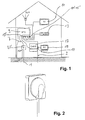
- Figure 1 is a wiring situation in a house shown, usually in the dashed (line 2) adjacent area of responsibility of a network operator a coaxial line 1 led to a junction box 3 ' is.
- a coaxial connection cable can then be used on this connection box 7 a switching device 9 (NTU) connected be which connections for connecting a television 11 and a radio 13. This connection will not managed by participants.
- NTU switching device 9
- the mentioned connections 11 'to 15' for connecting the TV and radio can be managed by the user become, i.e. the user can do the appropriate here Connect the coaxial cable yourself.
- junction box 3 usually designed to function as Flush-mounted box can be installed.
- a connector housing body 4 with a mounting ring or mounting edge 25 which in known manner offset and in the circumferential direction circumferential slots 27 which are curved in a partially circular shape has, which open into a slot end in bores 29 or ends that have a larger drilling diameter than that Have width of the circumferential slots 27.
- This can using screws an antenna socket 3 with their mounting edge 25 in a housing or flush-mounted housing 33 used and firmly anchored.
- an adapter 35 provided a middle, a free passage allowing, in the embodiment shown ring-shaped designed middle section 37 and at least two opposite Has fastening sections 39.
- This Central section 37 frames a central central opening 38.
- Bores 41 are in the fastening sections mentioned provided to after placing the adapter on the Mounting edge 25 of a junction box by screwing in Screw 43 this adapter 35 on the mounting ring 25 and thus to be firmly anchored to the junction box.
- Screws used, preferably on the bore 29 in Mounting edge 25 are matched so that by screwing the screws 43 in this bore 29 are firmly anchored of the adapter 35 on the mounting edge 25 and thus on the Junction box can be guaranteed.
- a cover plate 45 is also provided according to the shape and dimension of the shape and size of the Housing 33 of the outlet can be adapted.
- this cover plate 45 substantially rectangular, i.e. square, formed and has a corresponding on its top 45 ' Indentation 47 with a central central opening 49.
- the circumferential slots 27 are also in this recess 47 corresponding to the holes 29 in the mounting edge 25 part-circular Circumferential slots 51 provided in the holes 53 ends.
- the width of the circumferential slots 51 and Bores 53 are of a corresponding diameter Threaded approach adjusted further screws 55, the bores 57 provided for this purpose are screwed into the adapter 35 can be.
- the Adapters 35 now cover plate 45 to the still open Junction box. If the screws 55 on the adapter 35 beforehand, at least in part have been screwed in, the corresponding screw heads engage 55 'through the bore 53. This opens the Possibility to slightly up the cover plate 45 in their final position, in which they are in appropriate alignment to the housing of the junction box comes to rest. Then the screws 55 can be tightened which engage the slots 51 in the cover plate 45 and thereby the cover plate 45 now firmly on the housing anchor the junction box.
- the cover plate 45 can also be attached by first on the housing body below Antenna socket and then the fastening screws 55 can be screwed in at the appropriate points.
- coaxial connection cable 7 attached coaxial connector 59 on the connector 61 of the socket.
- a coaxial connector 59 is a in the embodiment shown Angled connector used.
- the coaxial connector protrudes the central central opening 49 of the cover plate 45, whose coaxial cable 7 the edge of the cover plate 45th is led away across the board.
- This locking cap 63 has one radially extending cap exit 65 in the manner of a tunnel with radial outlet opening 67 for the led out coaxial connection cable 7. Furthermore, the Locking cap 63 located on the underside thereof and locking means 68 protruding axially in the direction of insertion of locking fingers 69 offset in the circumferential direction on, that is by offset in the circumferential direction Slots 70 are separated. The mentioned locking fingers 69 end in locking sections 71, the below Form a step heel project radially outwards. These locking fingers 69 are in the insertion direction one widening in a wedge shape opposite to the direction of insertion Ramp surface 73 provided.
- the dimensions are such that when the locking cap 63 is attached, the Latching fingers along the rectified ramp surface 75 the central center opening 49 of the cover plate 45, there increasingly towards each other, i.e. towards the central one Central longitudinal axis 77 (hereinafter also partially called Central axis 77 is referred to) are biased, wherein the locking sections 71 automatically overlap the edge 79 swing outwards so that the undercuts Locking sections 71 at the edge 79 of the cover plate 45 of the locking countermeasures 78 thus formed and the Locking cap can no longer be removed.
- Central longitudinal axis 77 hereinafter also partially called Central axis 77 is referred to
- a can at a certain point on the cover housing appropriately identified position 91 is provided be thinner on the housing wall, for example is trained.
- a screwdriver can be used here for the housing wall be pierced, with the result that the locking fingers can be preloaded inwards so that the locking flap 63 is removed from the cover plate 45 can be.
Landscapes
- Details Of Connecting Devices For Male And Female Coupling (AREA)
- Connector Housings Or Holding Contact Members (AREA)
- Mechanical Coupling Of Light Guides (AREA)
Abstract
- es ist ferner ein Adapter (35) vorgesehen,
- an dem Adapter (35) ist die Abdeckplatte (45) befestigt,
- der Adapter (35) und die Abdeckplatte (45) weisen eine zentrale Mittelöffnung (38, 49) für die Durchführung des Anschlusssteckers (59) auf,
- die Verriegelungskappe (63) weist an deren Unterseite mittig angeordnet kreisförmig gestaltete Rastmittel (68) auf, und
- die Rastmittel (68) hintergreifen wiederum Rastgegenmittel (78) an der Mittelöffnung (49) der Abdeckplatte (45).
Description
- Figur 1 :
- eine schematische Darstellung einer häuslichen Verkabelungssituation;
- Figur 2 :
- eine Abdeckung mit einer Abdeckkappe auf einer darunter befindlichen und in der Zeichnung nicht weiter dargestellten Unterputz-Anschlussdose mit aus der Abdeckkappe herausgeführten Koaxialkabel;
- Figur 3 :
- eine Draufsicht auf das Ausführungsbeispiel gemäß Figur 2;
- Figur 4 :
- eine Querschnittsdarstellung längs der Linie B-B in Figur 3;
- Figur 5 :
- eine weitere Querschnittsdarstellung in einer um die zentrale Vertikalachse der Anschlusssteckdose verdrehte Schnittachse;
- Figur 6 :
- eine perspektivische Darstellung eines Adapterteils;
- Figur 7 :
- eine Draufsicht auf das in Figur 6 dargestellte Adapterteil;
- Figur 8 :
- eine perspektivische Darstellung der Anschlusssteckdose mit vormontiertem Adapterteil bei aufgestecktem Anschlusskabel vor Montage des Abdeckgehäuses und der Verriegelungskappe;
- Figur 9 :
- eine perspektivische Darstellung der Verriegelungskappe;
- Figur 10 :
- eine Querschnittsdarstellung durch die Verriegelungskappe in Längsrichtung durch den Koaxialkabel-Anschlussbereich; und
- Figur 11 :
- eine quer dazu verlaufende Querschnittsdarstellung durch die Verriegelungskappe.
Claims (9)
- Verriegelbare Anschlussdose für einen gesteckten Anschlussstecker mit den folgenden Merkmalengekennzeichnet durch die folgenden weiteren Merkmalees ist ein Anschluss-Gehäusekörper (4) vorgesehen,es ist ferner eine Abdeckplatte (45) vorgesehen, die an dem Anschluss-Gehäusekörper (4) lösbar befestigt ist,es ist eine Verriegelungskappe (63) vorgesehen, die mittels Rastmittel an der Abdeckplatte (45) angeordnet ist,die Verriegelungskappe (63) kann ohne Zerstörung derselben nicht gelöst werden, unddie Verriegelungskappe (63) übergreift den Anschlussstecker (59) im gesteckten Zustand,es ist ferner ein Adapter (35) vorgesehen,an dem Adapter (35) ist die Abdeckplatte (45) befestigt,der Adapter (35) und die Abdeckplatte (45) weisen eine zentrale Mittelöffnung (38, 49) für die Durchführung des Anschlusssteckers (59) auf,die Verriegelungskappe (63) weist an deren Unterseite mittig angeordnet kreisförmig gestaltete Rastmittel (68) auf, unddie Rastmittel (68) hintergreifen wiederum Rastgegenmittel (78) an der Mittelöffnung (49) der Abdeckplatte (45).
- Verriegelbare Anschlussdose nach Anspruch 1, dadurch gekennzeichnet, dass die Verriegelungskappe (63) in Draufsicht zumindest im wesentlichen kreisförmig gestaltet ist und gegenüber der Abdeckkappe (45) um eine im wesentlichen senkrecht zur Abdeckkappe (63) verlaufenden Zentralachse (77) verdrehbar ist.
- Verriegelbare Anschlussdose nach Anspruch 1 oder 2, dadurch gekennzeichnet, dass die Verriegelungskappe (63) einen zumindest im wesentlichen radial verlaufenden Kappenausgang (65) umfasst, vorzugsweise mit einer radialen Austrittsöffnung (67), worüber das Koaxialkabel (7) herausführbar ist.
- Verriegelbare Anschlussdose nach einem der Ansprüche 1 bis 3, dadurch gekennzeichnet, dass die an der Unterseite der Verriegelungskappe (63) ausgebildeten Rastmittel (68) aus mehreren Rastfingern (69) bestehen, die durch in Umfangsrichtung versetzt liegende Schlitze (70) voneinander getrennt sind.
- Verriegelbare Anschlussdose nach einem der Ansprüche 1 bis 4, dadurch gekennzeichnet, dass die Rastgegenmittel (78) vorzugsweise in Form von Rastfingern (69) in Steckrichtung vorlaufende Rastabschnitte (71) aufweisen, die jeweils mit einer rückwärtig liegenden hinterschnittenen Verankerungsfläche versehen sind, die in verrastetem Zustand mit einer Gegenanschlagsfläche (79) zusammenwirken, die an der in Steckrichtung innenliegenden Ende der Mittelöffnung (49) der Abdeckplatte (45) ausgebildet ist.
- Verriegelbare Anschlussdose nach einem der Ansprüche 1 bis 5, dadurch gekennzeichnet, dass die Rastfinger (69) in Steckrichtung sich keilförmig verjüngende Auflaufflächen (73) aufweisen, die mit entsprechenden Auflaufflächen (75) an der Mittelöffnung (45) zusammenwirken.
- Verriegelbare Anschlussdose nach einem der Ansprüche 1 bis 6, dadurch gekennzeichnet, dass die Abdeckplatte (45) vorzugsweise mittels Schrauben (55) direkt an dem Anschluss-Gehäusekörper (4) bzw. einem dort ausgebildeten Montagerand (25) befestigbar ist.
- Verriegelbare Anschlussdose nach einem der Ansprüche 1 bis 7, dadurch gekennzeichnet, dass das Abdeckgehäuse (45) über weitere Schrauben (55) an dem Adapter (35) fest verankerbar ist.
- Verriegelbare Anschlussdose nach einem der Ansprüche 1 bis 8, dadurch gekennzeichnet, dass die Rastmittel (68) vorzugsweise in Form von Rastfingern (69) in Draufsicht teilkreisförmig gestaltet sind, und mit einer oder mehreren zumindest teilkreisförmig oder als Vollkreis ausgebildeten Rastgegenmittel (78) zusammenwirken.
Applications Claiming Priority (2)
| Application Number | Priority Date | Filing Date | Title |
|---|---|---|---|
| DE10035383 | 2000-07-20 | ||
| DE10035383A DE10035383C2 (de) | 2000-07-20 | 2000-07-20 | Verriegelbare Anschlussdose für einen gesteckten Anschlussstecker |
Publications (3)
| Publication Number | Publication Date |
|---|---|
| EP1174954A2 true EP1174954A2 (de) | 2002-01-23 |
| EP1174954A3 EP1174954A3 (de) | 2003-03-12 |
| EP1174954B1 EP1174954B1 (de) | 2003-11-12 |
Family
ID=7649632
Family Applications (1)
| Application Number | Title | Priority Date | Filing Date |
|---|---|---|---|
| EP01117466A Expired - Lifetime EP1174954B1 (de) | 2000-07-20 | 2001-07-19 | Verriegelbare Anschlussdose für einen gesteckten Anschlussstecker |
Country Status (3)
| Country | Link |
|---|---|
| EP (1) | EP1174954B1 (de) |
| AT (1) | ATE254343T1 (de) |
| DE (1) | DE10035383C2 (de) |
Cited By (1)
| Publication number | Priority date | Publication date | Assignee | Title |
|---|---|---|---|---|
| FR2928786A1 (fr) * | 2008-03-17 | 2009-09-18 | Peugeot Citroen Automobiles Sa | Distributeur de faisceaux electriques avec coupelle de protection |
Families Citing this family (3)
| Publication number | Priority date | Publication date | Assignee | Title |
|---|---|---|---|---|
| DE102004019757A1 (de) * | 2004-04-23 | 2005-12-01 | Kostal Kontakt Systeme Gmbh | Elektrischer Steckverbinder für ein Kraftfahrzeug mit einem Plombierriegel |
| DE102005015268A1 (de) | 2005-04-04 | 2006-10-12 | Adc Gmbh | Steckverbindung |
| DE102017204744B4 (de) * | 2017-03-21 | 2019-11-14 | Leoni Kabel Gmbh | Vorrichtung zur Überwachung eines Gebäudes |
Family Cites Families (9)
| Publication number | Priority date | Publication date | Assignee | Title |
|---|---|---|---|---|
| US3496176A (en) * | 1968-06-19 | 1970-02-17 | Allied Chem | Melamine purification |
| US4851612A (en) * | 1987-09-08 | 1989-07-25 | Peckham Albert E | Outlet protector |
| DE3743192A1 (de) * | 1987-12-19 | 1989-06-29 | Asea Brown Boveri | Befestigungssystem fuer abdeckungen |
| FR2640237B1 (fr) * | 1988-12-13 | 1991-02-08 | Radiall Sa | Dispositif d'obturation a indication de violation pour embase coaxiale |
| DE9108763U1 (de) * | 1991-07-12 | 1991-09-05 | Kräcker AG telekom technik, 1000 Berlin | Telefon-Steckdose |
| DE9315054U1 (de) * | 1993-10-05 | 1993-12-16 | Seewald, Gerhard, 90542 Eckental | Bewegliche Steckdose |
| WO1995026579A1 (en) * | 1994-03-28 | 1995-10-05 | Paige Innovations Inc. | Cover plate assembly for wall outlet |
| DE19642687C2 (de) * | 1996-10-16 | 1999-08-05 | Daimler Chrysler Ag | Verriegelungsvorrichtung zur Absicherung einer Ladesteckdose |
| DE19645075C2 (de) * | 1996-10-31 | 1998-09-10 | Kathrein Werke Kg | Antennendose |
-
2000
- 2000-07-20 DE DE10035383A patent/DE10035383C2/de not_active Expired - Fee Related
-
2001
- 2001-07-19 AT AT01117466T patent/ATE254343T1/de not_active IP Right Cessation
- 2001-07-19 EP EP01117466A patent/EP1174954B1/de not_active Expired - Lifetime
Cited By (1)
| Publication number | Priority date | Publication date | Assignee | Title |
|---|---|---|---|---|
| FR2928786A1 (fr) * | 2008-03-17 | 2009-09-18 | Peugeot Citroen Automobiles Sa | Distributeur de faisceaux electriques avec coupelle de protection |
Also Published As
| Publication number | Publication date |
|---|---|
| EP1174954B1 (de) | 2003-11-12 |
| DE10035383C2 (de) | 2002-08-01 |
| ATE254343T1 (de) | 2003-11-15 |
| DE10035383A1 (de) | 2002-02-07 |
| EP1174954A3 (de) | 2003-03-12 |
Similar Documents
| Publication | Publication Date | Title |
|---|---|---|
| DE68903541T2 (de) | Stossbefestiger. | |
| EP2450729B1 (de) | Baukasten für Befestigungsvorrichtung | |
| EP2240987B1 (de) | Steckvorrichtung | |
| EP2382905A2 (de) | Hohlprofil | |
| EP0567821B1 (de) | Rohrschelle | |
| DE4237674A1 (de) | Rohrschelle | |
| EP0058739A2 (de) | Kabeldurchführung mit Zugentlastung | |
| EP1174954B1 (de) | Verriegelbare Anschlussdose für einen gesteckten Anschlussstecker | |
| EP0964493A2 (de) | Winkelförmige Leitungseinführung mit einer Trennstelle zwischen den beiden Schenkeln | |
| EP1604432A1 (de) | Sicherungselement zum sichern gegen öffnen einer steckverbindung zwischen einem kabelbaumstecker und einem kupplungsstecker. | |
| EP1004713B1 (de) | Abdeck-Rosette | |
| DE3515384A1 (de) | Tuerschloss | |
| DE10125625C2 (de) | Dichtungstülle insbesondere für einen Kabelübergangskasten | |
| DE3807626A1 (de) | Befestigungsvorrichtung | |
| EP3376060A1 (de) | Schnellverschraubung, insbesondere zum verbinden von mehrteiligen baugruppen | |
| DE9210795U1 (de) | Sicherheitsbeschlag für mit einem Profilschließzylinder versehene Türschlösser | |
| EP3444486B1 (de) | Befestigungseinheit für zaunteile | |
| EP0959536A1 (de) | Steckdosenleiste | |
| DE102011076210B4 (de) | Befestigungsanordnung für zwei benachbarte Sanitärarmaturen | |
| EP1649111A1 (de) | Halterungsanordnung für eine brause | |
| EP1570135B1 (de) | Vorrichtung mit einem Brausekopf und einer Halterung für den Brausekopf | |
| EP2933401A1 (de) | Einrichtung zum Spannen von Strangelementen | |
| DE3105316C2 (de) | Kabeldurchführung mit Zugentlastung | |
| DE202010001441U1 (de) | Justiersystem für Bauelemente | |
| DE202005004333U1 (de) | Deckensteckdose mit Lampenanschluß |
Legal Events
| Date | Code | Title | Description |
|---|---|---|---|
| PUAI | Public reference made under article 153(3) epc to a published international application that has entered the european phase |
Free format text: ORIGINAL CODE: 0009012 |
|
| AK | Designated contracting states |
Kind code of ref document: A2 Designated state(s): AT BE CH CY DE DK ES FI FR GB GR IE IT LI LU MC NL PT SE TR |
|
| AX | Request for extension of the european patent |
Free format text: AL;LT;LV;MK;RO;SI |
|
| PUAL | Search report despatched |
Free format text: ORIGINAL CODE: 0009013 |
|
| AK | Designated contracting states |
Kind code of ref document: A3 Designated state(s): AT BE CH CY DE DK ES FI FR GB GR IE IT LI LU MC NL PT SE TR Designated state(s): AT BE CH CY DE DK ES FI FR GB GR IE IT LI LU MC NL PT SE TR |
|
| AX | Request for extension of the european patent |
Extension state: AL LT LV MK RO SI |
|
| GRAH | Despatch of communication of intention to grant a patent |
Free format text: ORIGINAL CODE: EPIDOS IGRA |
|
| RIN1 | Information on inventor provided before grant (corrected) |
Inventor name: BERGER, STEFAN Inventor name: STANISZEWSKI, WALTER |
|
| 17P | Request for examination filed |
Effective date: 20030403 |
|
| GRAS | Grant fee paid |
Free format text: ORIGINAL CODE: EPIDOSNIGR3 |
|
| GRAA | (expected) grant |
Free format text: ORIGINAL CODE: 0009210 |
|
| AK | Designated contracting states |
Kind code of ref document: B1 Designated state(s): AT BE CH CY DK ES FI FR GB GR IE IT LI LU MC NL PT SE TR |
|
| AX | Request for extension of the european patent |
Extension state: AL LT LV MK RO SI |
|
| PG25 | Lapsed in a contracting state [announced via postgrant information from national office to epo] |
Ref country code: TR Free format text: LAPSE BECAUSE OF FAILURE TO SUBMIT A TRANSLATION OF THE DESCRIPTION OR TO PAY THE FEE WITHIN THE PRESCRIBED TIME-LIMIT Effective date: 20031112 Ref country code: IT Free format text: LAPSE BECAUSE OF FAILURE TO SUBMIT A TRANSLATION OF THE DESCRIPTION OR TO PAY THE FEE WITHIN THE PRESCRIBED TIME-LIMIT;WARNING: LAPSES OF ITALIAN PATENTS WITH EFFECTIVE DATE BEFORE 2007 MAY HAVE OCCURRED AT ANY TIME BEFORE 2007. THE CORRECT EFFECTIVE DATE MAY BE DIFFERENT FROM THE ONE RECORDED. Effective date: 20031112 Ref country code: IE Free format text: LAPSE BECAUSE OF FAILURE TO SUBMIT A TRANSLATION OF THE DESCRIPTION OR TO PAY THE FEE WITHIN THE PRESCRIBED TIME-LIMIT Effective date: 20031112 Ref country code: GB Free format text: LAPSE BECAUSE OF FAILURE TO SUBMIT A TRANSLATION OF THE DESCRIPTION OR TO PAY THE FEE WITHIN THE PRESCRIBED TIME-LIMIT Effective date: 20031112 Ref country code: FR Free format text: LAPSE BECAUSE OF FAILURE TO SUBMIT A TRANSLATION OF THE DESCRIPTION OR TO PAY THE FEE WITHIN THE PRESCRIBED TIME-LIMIT Effective date: 20031112 Ref country code: FI Free format text: LAPSE BECAUSE OF FAILURE TO SUBMIT A TRANSLATION OF THE DESCRIPTION OR TO PAY THE FEE WITHIN THE PRESCRIBED TIME-LIMIT Effective date: 20031112 Ref country code: ES Free format text: LAPSE BECAUSE OF FAILURE TO SUBMIT A TRANSLATION OF THE DESCRIPTION OR TO PAY THE FEE WITHIN THE PRESCRIBED TIME-LIMIT Effective date: 20031112 Ref country code: CY Free format text: LAPSE BECAUSE OF FAILURE TO SUBMIT A TRANSLATION OF THE DESCRIPTION OR TO PAY THE FEE WITHIN THE PRESCRIBED TIME-LIMIT Effective date: 20031112 |
|
| REG | Reference to a national code |
Ref country code: GB Ref legal event code: FG4D Free format text: NOT ENGLISH |
|
| REG | Reference to a national code |
Ref country code: CH Ref legal event code: EP |
|
| AKX | Designation fees paid |
Designated state(s): AT BE CH CY DK ES FI FR GB GR IE IT LI LU MC NL PT SE TR |
|
| REG | Reference to a national code |
Ref country code: IE Ref legal event code: FG4D Free format text: GERMAN |
|
| PG25 | Lapsed in a contracting state [announced via postgrant information from national office to epo] |
Ref country code: SE Free format text: LAPSE BECAUSE OF FAILURE TO SUBMIT A TRANSLATION OF THE DESCRIPTION OR TO PAY THE FEE WITHIN THE PRESCRIBED TIME-LIMIT Effective date: 20040212 Ref country code: GR Free format text: LAPSE BECAUSE OF FAILURE TO SUBMIT A TRANSLATION OF THE DESCRIPTION OR TO PAY THE FEE WITHIN THE PRESCRIBED TIME-LIMIT Effective date: 20040212 Ref country code: DK Free format text: LAPSE BECAUSE OF FAILURE TO SUBMIT A TRANSLATION OF THE DESCRIPTION OR TO PAY THE FEE WITHIN THE PRESCRIBED TIME-LIMIT Effective date: 20040212 |
|
| GBV | Gb: ep patent (uk) treated as always having been void in accordance with gb section 77(7)/1977 [no translation filed] |
Effective date: 20031112 |
|
| REG | Reference to a national code |
Ref country code: IE Ref legal event code: FD4D |
|
| PG25 | Lapsed in a contracting state [announced via postgrant information from national office to epo] |
Ref country code: LU Free format text: LAPSE BECAUSE OF NON-PAYMENT OF DUE FEES Effective date: 20040719 Ref country code: AT Free format text: LAPSE BECAUSE OF NON-PAYMENT OF DUE FEES Effective date: 20040719 |
|
| PG25 | Lapsed in a contracting state [announced via postgrant information from national office to epo] |
Ref country code: MC Free format text: LAPSE BECAUSE OF NON-PAYMENT OF DUE FEES Effective date: 20040731 |
|
| PLBE | No opposition filed within time limit |
Free format text: ORIGINAL CODE: 0009261 |
|
| STAA | Information on the status of an ep patent application or granted ep patent |
Free format text: STATUS: NO OPPOSITION FILED WITHIN TIME LIMIT |
|
| 26N | No opposition filed |
Effective date: 20040813 |
|
| EN | Fr: translation not filed | ||
| PG25 | Lapsed in a contracting state [announced via postgrant information from national office to epo] |
Ref country code: LI Free format text: LAPSE BECAUSE OF NON-PAYMENT OF DUE FEES Effective date: 20050731 Ref country code: CH Free format text: LAPSE BECAUSE OF NON-PAYMENT OF DUE FEES Effective date: 20050731 |
|
| REG | Reference to a national code |
Ref country code: CH Ref legal event code: PL |
|
| PGFP | Annual fee paid to national office [announced via postgrant information from national office to epo] |
Ref country code: NL Payment date: 20060718 Year of fee payment: 6 |
|
| PGFP | Annual fee paid to national office [announced via postgrant information from national office to epo] |
Ref country code: BE Payment date: 20060727 Year of fee payment: 6 |
|
| PG25 | Lapsed in a contracting state [announced via postgrant information from national office to epo] |
Ref country code: PT Free format text: LAPSE BECAUSE OF NON-PAYMENT OF DUE FEES Effective date: 20040412 |
|
| BERE | Be: lapsed |
Owner name: *KATHREIN-WERKE K.G. Effective date: 20070731 |
|
| NLV4 | Nl: lapsed or anulled due to non-payment of the annual fee |
Effective date: 20080201 |
|
| PG25 | Lapsed in a contracting state [announced via postgrant information from national office to epo] |
Ref country code: NL Free format text: LAPSE BECAUSE OF NON-PAYMENT OF DUE FEES Effective date: 20080201 |
|
| PG25 | Lapsed in a contracting state [announced via postgrant information from national office to epo] |
Ref country code: BE Free format text: LAPSE BECAUSE OF NON-PAYMENT OF DUE FEES Effective date: 20070731 |