EP1174670A1 - Trockenkammer zum Trocknen einer bedruckten Bahn - Google Patents
Trockenkammer zum Trocknen einer bedruckten Bahn Download PDFInfo
- Publication number
- EP1174670A1 EP1174670A1 EP01110906A EP01110906A EP1174670A1 EP 1174670 A1 EP1174670 A1 EP 1174670A1 EP 01110906 A EP01110906 A EP 01110906A EP 01110906 A EP01110906 A EP 01110906A EP 1174670 A1 EP1174670 A1 EP 1174670A1
- Authority
- EP
- European Patent Office
- Prior art keywords
- web
- drying chamber
- drying
- sheets
- printed
- Prior art date
- Legal status (The legal status is an assumption and is not a legal conclusion. Google has not performed a legal analysis and makes no representation as to the accuracy of the status listed.)
- Withdrawn
Links
- 238000001035 drying Methods 0.000 title claims abstract description 37
- 238000007664 blowing Methods 0.000 claims description 4
- 238000004804 winding Methods 0.000 description 2
- 230000001154 acute effect Effects 0.000 description 1
- 239000002184 metal Substances 0.000 description 1
Images

Classifications
-
- F—MECHANICAL ENGINEERING; LIGHTING; HEATING; WEAPONS; BLASTING
- F26—DRYING
- F26B—DRYING SOLID MATERIALS OR OBJECTS BY REMOVING LIQUID THEREFROM
- F26B13/00—Machines and apparatus for drying fabrics, fibres, yarns, or other materials in long lengths, with progressive movement
- F26B13/10—Arrangements for feeding, heating or supporting materials; Controlling movement, tension or position of materials
Definitions
- the invention relates to a drying chamber for drying a printed web, consisting of a housing with inlet and outlet openings for the web and at least one infrared radiator directed at the web and / or warm air blowing air nozzles blowing on the web, preferably drying chamber for flexographic printing printed webs on the bridge between the flexographic press and the unwinding and reeling devices is arranged.
- drying printed Sheets in drying chambers have the problem of being good and rapid drying is hindered by the fact that through an inlet slot in the web entering the drying chamber entrains air that adheres to the web forms an insulating layer that prevents good drying.
- the object of the invention is therefore a drying chamber of the type specified To create a way that eliminates an insulating layer of air covering the web so that they do not hinder and delay drying of the web can.
- Turbulence generators are arranged above the track.
- the web to be dried usually runs into the drying chamber with the printed side facing upwards, so that the turbulence generators arranged above the web co-operate with the web a turbulent air flow, which the entrained by the train isolating air layer or boundary layer by swirling and eliminated so that those consisting of blown air nozzles and / or IR radiators Drying facilities the web unhindered by an insulating layer of air can act.
- Turbulence generators are expediently arranged on both sides of the web.
- the turbulence generator can be made across the direction of travel of the web and parallel to this arranged inclined or curved sheets.
- the sloping metal sheets are advantageously at an acute angle the direction of travel of the web so that it envelops the web Peel air layers as it were.
- the web Sheets are arranged in the shape of a cylindrical shell. These are preferred arranged so that the concave sides of the sheets face each other.
- the curved sheets preferably have a wing-shaped profile.
- FIG. 1 shows an eight-color flexographic printing press 1 with eight printing units, whose pressure rollers are attached to a common impression cylinder are.
- a drying chamber 5 On the bridge 4 there is a drying chamber 5 surrounded by a housing, through which the printed web from the flexographic printing machine 1 to the reel-up running.
- the housing 6 of the drying chamber 5 has an inlet slot 7 and an outlet slot 8 for the printed web to be dried.
- In the housing 6 of the drying chamber 5 are preferably curved Web guide rollers 10 stored, over which the printed web 11 to be dried runs.
- Drying devices are on the printed side above the web 11 to be dried directed in the illustrated embodiment from a convector 12 and infrared radiators 13 exist.
- the convector 12 can be a Act blow nozzle arrangement that blows warm air onto the printed web 11.
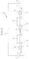
- bowl-shaped sheets 14, 15 are arranged above and below the web, whose concave sides face each other.
- the cupped curved Sheets 14, 15 are arranged at a distance from the web 11 in such a way that their concave sides face each other, so that gap-shaped inlet and outlet slots are formed.
- the bowl-shaped sheets 14, 15 are arranged in mirror image to the pass plane of the web 11, so that due the air currents from the sheets exerting suction on each other cancel.
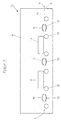
- FIG. 3 shows alternative configurations of the turbulence generators which can be used alone or in combination.
- Adjacent at the inlet and outlet areas are bowl-shaped sheets or bodies 18, 19 are provided, which are curved, the concave sides facing each other are.
- the sheets or bodies 18, 19 are mirror images of the flow plane of the arranged to dry web 11.
- Sheets 20, 21 In the middle area of the drying chamber are sloping or slightly curved Sheets 20, 21 arranged, their cutting edges leading in opposite directions the direction of travel of the web 11 are employed on both sides against this, so that they peel off the layers of air enveloping the web.
- the sheets 20, 21 are arranged in mirror image to the pass plane of the web 11.
Landscapes
- Engineering & Computer Science (AREA)
- Textile Engineering (AREA)
- Mechanical Engineering (AREA)
- General Engineering & Computer Science (AREA)
- Drying Of Solid Materials (AREA)
- Supply, Installation And Extraction Of Printed Sheets Or Plates (AREA)
Abstract
Description
- Fig. 1
- eine Acht-Farben-Flexodruckmaschine mit Ab- und Aufwickeleinrichtungen für die bedruckten Bahnen und eine beide verbindende Brücke mit auf dieser angeordneten Trockenkammer in schematischer Seitenansicht,
- Fig. 2
- eine schematische Seitenansicht einer ersten Ausführungsform der Trockenkammer mit abgehobener Vorderwand in schematischer Darstellung und
- Fig. 3
- eine der Fig. 2 entsprechende zweite Ausführungsform der Trockenkammer.
Claims (6)
- Trockenkammer (5) zum Trocknen einer bedruckten Bahn (11), bestehend aus einem Gehäuse (6) mit Ein- und Auslauföffnungen (7, 8) für die Bahn (11) und mit mindestens einem auf die Bahn (11) gerichteten Infrarotstrahler (13) und/oder warme Luft auf die Bahn blasenden Blasluftdüsen (12), vorzugsweise Trockenkammer für im Flexodruck bedruckte Bahnen, die auf der Brücke (4) zwischen der Flexodruckmaschine (1) und den Ab- und Aufrolleinrichtungen für die Bahn angeordnet ist,
dadurch gekennzeichnet, daß in der Trockenkammer (5) oberhalb der Bahn (11) Turbulenzerzeuger (14, 18, 20) angeordnet sind. - Trockenkammer nach Anspruch 1, dadurch gekennzeichnet, daß beidseits der Bahn Turbulenzerzeuger (14, 18, 20) angeordnet sind.
- Trockenkammer nach Anspruch 1 oder 2, dadurch gekennzeichnet, daß die Turbulenzerzeuger aus quer zu der Laufrichtung der Bahn (11) und parallel zu dieser angeordneten schrägstehenden oder gekrümmten Blechen (14, 18, 20) bestehen.
- Trockenkammer nach Anspruch 2 oder 3, dadurch gekennzeichnet, daß beidseits der Bahn zylinderschalenförmig gekrümmte Bleche (14, 15; 18, 19) angeordnet sind.
- Trockenkammer nach Anspruch 4, dadurch gekennzeichnet, daß die konkaven Seiten der Bleche einander zugewandt sind.
- Trockenkammer nach Anspruch 4 oder 5, dadurch gekennzeichnet, daß die gekrümmten Bleche (18, 19) ein tragflügelförmiges Profil besitzen.
Applications Claiming Priority (2)
| Application Number | Priority Date | Filing Date | Title |
|---|---|---|---|
| DE10034708A DE10034708A1 (de) | 2000-07-17 | 2000-07-17 | Trockenkammer zum Trocknen einer bedruckten Bahn |
| DE10034708 | 2000-07-17 |
Publications (1)
| Publication Number | Publication Date |
|---|---|
| EP1174670A1 true EP1174670A1 (de) | 2002-01-23 |
Family
ID=7649199
Family Applications (1)
| Application Number | Title | Priority Date | Filing Date |
|---|---|---|---|
| EP01110906A Withdrawn EP1174670A1 (de) | 2000-07-17 | 2001-05-05 | Trockenkammer zum Trocknen einer bedruckten Bahn |
Country Status (3)
| Country | Link |
|---|---|
| US (1) | US6505419B2 (de) |
| EP (1) | EP1174670A1 (de) |
| DE (1) | DE10034708A1 (de) |
Families Citing this family (5)
| Publication number | Priority date | Publication date | Assignee | Title |
|---|---|---|---|---|
| DE10246271A1 (de) | 2002-10-02 | 2004-04-15 | Windmöller & Hölscher Kg | Verfahren und Vorrichtung zum Einstellen der Farbdichte auf einem Bedruckstoff |
| DE10257320B4 (de) * | 2002-12-06 | 2006-02-16 | Coatema Maschinenbau Gmbh | Kanalsystem für das thermische Behandeln von beschichteten Warenbahnen |
| US8322047B2 (en) * | 2007-06-29 | 2012-12-04 | Moore Wallace North America, Inc. | System and method for drying a freshly printed medium |
| DE102008025994B4 (de) | 2008-05-29 | 2011-06-09 | Windmöller & Hölscher Kg | Druckmaschine |
| US8967786B2 (en) | 2012-05-30 | 2015-03-03 | Antonio Monclus Velasco | Printing apparatus and methods |
Citations (9)
| Publication number | Priority date | Publication date | Assignee | Title |
|---|---|---|---|---|
| US2306019A (en) * | 1939-10-21 | 1942-12-22 | B F Sturtevant Co | Drying apparatus |
| US2308767A (en) * | 1939-05-18 | 1943-01-19 | Mark W Mayes | Apparatus for dehydrating yarn |
| US2473629A (en) * | 1944-11-16 | 1949-06-21 | Bernard R Andrews | Drying apparatus |
| US2804694A (en) * | 1953-12-04 | 1957-09-03 | Canada Wire & Cable Co Ltd | Ovens and heat treating apparatus |
| US3584846A (en) * | 1969-11-14 | 1971-06-15 | Lyle E Mccoy | Heating apparatus for elongate material |
| DE2417096A1 (de) * | 1974-04-08 | 1975-10-16 | Erich Ing Grad Hilgeroth | Vorrichtung zum behandeln, vorzugsweise trocknen von kontinuierlich durchlaufenden warenbahnen |
| US4201323A (en) * | 1978-10-12 | 1980-05-06 | W. R. Grace & Co. | High velocity web floating air bar having a recessed Coanda plate |
| US4843731A (en) * | 1986-03-06 | 1989-07-04 | Hilmar Vits | Device for floatably guiding webs of material by means of a gaseous or liquid medium |
| WO1997037182A1 (en) * | 1996-03-29 | 1997-10-09 | Minnesota Mining And Manufacturing Company | Apparatus and method for drying a coating on a substrate employing multiple drying subzones |
Family Cites Families (5)
| Publication number | Priority date | Publication date | Assignee | Title |
|---|---|---|---|---|
| US4767042A (en) * | 1987-06-11 | 1988-08-30 | Advance Systems Inc. | Paper web handling apparatus having improved air bar with fine scale turbulence generators |
| US5967457A (en) * | 1996-07-23 | 1999-10-19 | Thermo Wisconsin, Inc. | Airfoil web stabilization and turning apparatus and method |
| US5970627A (en) * | 1997-12-11 | 1999-10-26 | Thermo Wisconsin, Inc. | Active web stabilization apparatus |
| US6176184B1 (en) * | 1999-04-16 | 2001-01-23 | Paper Converting Machine Company | Dryer for flexographic and gravure printing |
| US6328852B1 (en) * | 1999-08-24 | 2001-12-11 | Kimberly-Clark Worldwide, Inc. | Method and apparatus for improving stability of moving webs |
-
2000
- 2000-07-17 DE DE10034708A patent/DE10034708A1/de not_active Ceased
-
2001
- 2001-05-05 EP EP01110906A patent/EP1174670A1/de not_active Withdrawn
- 2001-07-17 US US09/906,088 patent/US6505419B2/en not_active Expired - Fee Related
Patent Citations (9)
| Publication number | Priority date | Publication date | Assignee | Title |
|---|---|---|---|---|
| US2308767A (en) * | 1939-05-18 | 1943-01-19 | Mark W Mayes | Apparatus for dehydrating yarn |
| US2306019A (en) * | 1939-10-21 | 1942-12-22 | B F Sturtevant Co | Drying apparatus |
| US2473629A (en) * | 1944-11-16 | 1949-06-21 | Bernard R Andrews | Drying apparatus |
| US2804694A (en) * | 1953-12-04 | 1957-09-03 | Canada Wire & Cable Co Ltd | Ovens and heat treating apparatus |
| US3584846A (en) * | 1969-11-14 | 1971-06-15 | Lyle E Mccoy | Heating apparatus for elongate material |
| DE2417096A1 (de) * | 1974-04-08 | 1975-10-16 | Erich Ing Grad Hilgeroth | Vorrichtung zum behandeln, vorzugsweise trocknen von kontinuierlich durchlaufenden warenbahnen |
| US4201323A (en) * | 1978-10-12 | 1980-05-06 | W. R. Grace & Co. | High velocity web floating air bar having a recessed Coanda plate |
| US4843731A (en) * | 1986-03-06 | 1989-07-04 | Hilmar Vits | Device for floatably guiding webs of material by means of a gaseous or liquid medium |
| WO1997037182A1 (en) * | 1996-03-29 | 1997-10-09 | Minnesota Mining And Manufacturing Company | Apparatus and method for drying a coating on a substrate employing multiple drying subzones |
Also Published As
| Publication number | Publication date |
|---|---|
| US20020040536A1 (en) | 2002-04-11 |
| US6505419B2 (en) | 2003-01-14 |
| DE10034708A1 (de) | 2002-01-31 |
Similar Documents
| Publication | Publication Date | Title |
|---|---|---|
| DE3403642A1 (de) | Taschenventilationsvorrichtung fuer einen papiermaschinen-mehrzylindertrockner | |
| CH637089A5 (de) | Blaskasten zum schwebenden fuehren und/oder foerdern von bahnen oder bogen. | |
| DE3305749A1 (de) | Trockner | |
| DE3308869A1 (de) | Luftbalkenanordnung | |
| DE2935867A1 (de) | Gasduese zur behandlung von materialbahnen | |
| DE1474239C3 (de) | Verfahren und Einrichtung zur Stabilisierung der Lage unter Wirkung eines Blasmittels schwebend geführter Warenbahnen | |
| DE2458455C2 (de) | Vorrichtung zum Trocknen einer sich bewegenden Materialbahn | |
| DE2917765C2 (de) | Düse für einen Schwebetrockner | |
| DE3818600C2 (de) | ||
| EP1225046B1 (de) | Druckzylinder zum Aufnehmen einer Druckhülse | |
| DE3706541A1 (de) | Vorrichtung zum stabilisieren des laufes einer warenbahn, insbesondere zum stabilisieren einer papierbahn in der trockenpartie einer papiermaschine | |
| DE19619547A1 (de) | Luftkissendüse und Vorrichtung zur Wärmebehandlung einer kontinuierlich bewegten Warenbahn mit Luftkissendüsen | |
| DE3318861C1 (de) | Vorrichtung zum schwebenden Fuehren von Materialbahnen,insbesondere mit einer Heizeinrichtung zum Gluehen von Aluminiumbaendern | |
| DE69511702T2 (de) | Vorrichtung zur verminderung des effektes der neigung einer papierbahn zum haften auf einem trockenzylinder einer papiermaschine | |
| CH666115A5 (de) | Coanda-trockner. | |
| DE2056889A1 (de) | Behandlungsvorrichtung, insbesondere für die Wärmebehandlung von bahnförmigen Materialien | |
| DE3007752C2 (de) | Anordnung zur Beaufschlagung von Warenbahnen | |
| DE3815211A1 (de) | Papierbahnbehandlungsvorrichtung | |
| EP0277159B1 (de) | Vorrichtung zum beaufschlagen von materialbahnen mit strömungsmedium | |
| DE2911685C2 (de) | Blaskasten zum schwebenden Führen von Warenbahnen | |
| DE2256087C3 (de) | Vorrichtung zum Trocknen einer auf einem im wesentlichen eben geführten Träger aufliegenden Warenbahn | |
| DE10034708A1 (de) | Trockenkammer zum Trocknen einer bedruckten Bahn | |
| DE2351406C3 (de) | Ausblase- und Absaugvorrichtung für Materialbahntrockner | |
| DE3505769A1 (de) | Streicheinrichtung | |
| EP0291832A1 (de) | Vorrichtung zum Trocknen von freigeführten Materialbahnen mittels freigeführter Luftkissendüsen |
Legal Events
| Date | Code | Title | Description |
|---|---|---|---|
| PUAI | Public reference made under article 153(3) epc to a published international application that has entered the european phase |
Free format text: ORIGINAL CODE: 0009012 |
|
| AK | Designated contracting states |
Kind code of ref document: A1 Designated state(s): CH DE ES FR GB IT LI Kind code of ref document: A1 Designated state(s): AT BE CH CY DE DK ES FI FR GB GR IE IT LI LU MC NL PT SE TR |
|
| AX | Request for extension of the european patent |
Free format text: AL;LT;LV;MK;RO;SI |
|
| 17P | Request for examination filed |
Effective date: 20020723 |
|
| AKX | Designation fees paid |
Free format text: CH DE ES FR GB IT LI |
|
| STAA | Information on the status of an ep patent application or granted ep patent |
Free format text: STATUS: THE APPLICATION IS DEEMED TO BE WITHDRAWN |
|
| 18D | Application deemed to be withdrawn |
Effective date: 20031202 |