EP1174020A1 - Schleifvorrichtung - Google Patents
Schleifvorrichtung Download PDFInfo
- Publication number
- EP1174020A1 EP1174020A1 EP01115146A EP01115146A EP1174020A1 EP 1174020 A1 EP1174020 A1 EP 1174020A1 EP 01115146 A EP01115146 A EP 01115146A EP 01115146 A EP01115146 A EP 01115146A EP 1174020 A1 EP1174020 A1 EP 1174020A1
- Authority
- EP
- European Patent Office
- Prior art keywords
- grinding
- grindstone
- knife
- chopping
- controller
- Prior art date
- Legal status (The legal status is an assumption and is not a legal conclusion. Google has not performed a legal analysis and makes no representation as to the accuracy of the status listed.)
- Granted
Links
- 230000033001 locomotion Effects 0.000 claims abstract description 28
- 238000000034 method Methods 0.000 claims description 27
- 239000004575 stone Substances 0.000 claims description 17
- 239000004459 forage Substances 0.000 claims description 4
- 239000010902 straw Substances 0.000 abstract 1
- 238000003306 harvesting Methods 0.000 description 6
- 230000000875 corresponding effect Effects 0.000 description 4
- 239000000463 material Substances 0.000 description 4
- 238000006073 displacement reaction Methods 0.000 description 3
- 238000013459 approach Methods 0.000 description 2
- 230000001788 irregular Effects 0.000 description 2
- 238000005259 measurement Methods 0.000 description 2
- 230000029305 taxis Effects 0.000 description 2
- 244000025254 Cannabis sativa Species 0.000 description 1
- 241001124569 Lycaenidae Species 0.000 description 1
- 244000046127 Sorghum vulgare var. technicum Species 0.000 description 1
- 241000209149 Zea Species 0.000 description 1
- 235000005824 Zea mays ssp. parviglumis Nutrition 0.000 description 1
- 235000002017 Zea mays subsp mays Nutrition 0.000 description 1
- 235000005822 corn Nutrition 0.000 description 1
- 230000002596 correlated effect Effects 0.000 description 1
- 230000002950 deficient Effects 0.000 description 1
- 230000001419 dependent effect Effects 0.000 description 1
- 230000001939 inductive effect Effects 0.000 description 1
- 238000004519 manufacturing process Methods 0.000 description 1
- 239000004576 sand Substances 0.000 description 1
- 238000010408 sweeping Methods 0.000 description 1
- 230000032258 transport Effects 0.000 description 1
Images



Classifications
-
- A—HUMAN NECESSITIES
- A01—AGRICULTURE; FORESTRY; ANIMAL HUSBANDRY; HUNTING; TRAPPING; FISHING
- A01F—PROCESSING OF HARVESTED PRODUCE; HAY OR STRAW PRESSES; DEVICES FOR STORING AGRICULTURAL OR HORTICULTURAL PRODUCE
- A01F29/00—Cutting apparatus specially adapted for cutting hay, straw or the like
- A01F29/09—Details
- A01F29/22—Arrangement of knife sharpening devices
Definitions
- the invention relates to a grinding device with a Grindstone for sharpening at least one knife Chopping device, a movement device for moving the Grinding stone, a measuring device for providing a Signal that provides information about the shape of the cutting edge of the knife, and a controller that controls the moving device depending on that of the measuring device provided signal controls.
- DE 40 23 114 A describes a method for determining the Sharpness of chopping knives described in which the sharpness of the Chopper knife by one attached to the grinder magnetic encoder is measured.
- the means of Values measured by the encoder are used to inform the operator of the Forage harvester to inform when the chopping knife have to be sanded.
- DE 199 03 153 C suggests the state of wear single chopper knife by measuring the load on the Shear bar counter to the flow direction of the crop flow and across to capture the flow direction of the crop flow. If the measured wear condition indicates blunt knives gave the user appropriate information or automatically the crop flow stopped or the shear bar adjusted or a grinding process initiated.
- the problem underlying the invention is seen in to provide an improved grinder.
- the grinder's moving device to control such that the cutting edge of the knife to be ground into a desired shape becomes.
- a control receives one Signal provided by a measuring device and information about the current shape of the knife or the Knife contains.
- the movement device of the grindstone will controlled by the controller in such a way that the grindstone Cutting edge of the knife brings in a certain target shape which is a predetermined shape or a sub Several presets can be selected or entered as desired can act.
- the controller made a comparison between that of the Measuring device provided information about the actual shape the cutting edge and the target shape and the Movement device depending on the result of the Control comparison.
- the controller can work in different ways.
- the actual shape of the cutting edge would be conceivable query and then the movement device depending the difference between the target shape and the actual shape Taxes. It is first determined (a priori) how much Material where to be sanded, and then a corresponding one Grinding performed.
- the control signals are the Measuring device for the entire width of the chopping device feed what by scanning the width of the chopper can be done. From these signals, the Control derive information about how far that Grind the knife to get the desired shape.
- the controller is preferably a Information about the radius of the enveloping circle of each of Grindstone machined area of the chopper fed.
- the chopping device is so long processed with the grindstone until the signal of Measuring device across the width of the chopper at least approximately to the desired target shape suggesting.
- the chopper device can be a chopper drum act in open or closed form on which several Knives are attached.
- the chopper drum is on a shaft arranged, which is set in rotation during grinding and usually compared to normal chop operation Opposite direction turns.
- the measuring device detects such Chopping drums provide information about the distance between the Shaft and the cutting edges of the knives, i.e. over the radius of the enveloping circle described by the cutting edges.
- This Information can be an absolute or a relative value correspond.
- a relative value is, for example, the distance between the cutting edges of the knives and a shear bar or a grindstone, while the radius of the enveloping circle Cutting edges is an absolute value.
- the invention can also on chopping devices of disc wheel choppers Find use. There is not the radius of the cutting edges the knife captures but its axial position.
- the target shape of the cutting edges of the knives there is primarily one Shaft of the chopper drum parallel cutting edge, or one over the width of the chopper drum looks slightly concave in shape of the cutting edges. It should be noted that only that Shape of the cutting edge is specified, but not the (absolute) distance from the shaft of the chopper drum, which at every grinding process gets smaller. For disc wheel choppers the target shape is usually orthogonal to the wave Be the cutting edge.
- the grindstone is across the width of the Chopper transporting and / or him Movement device to be delivered by the control in Controlled and dependent on the signal of the measuring device moves the grindstone so that deviations in the shape of the Cutting edges of the knives are automatically compensated.
- the movement device can move the grindstone in in a non-linear manner over the chopping device method.
- the grindstone is in one place the longer left standing (or moved the slower) the further the Envelope of the cutting edges of the knives removed from the shaft is.
- the grindstone can be on one in particular Place to be left until the desired one Envelope diameter was achieved, or a certain Output signal of the measuring device results. Then will the grindstone moves on.
- the moving device can grind the stone continuously move across the width of the chopper, until a constant or desired radius of the enveloping circle Knife is achieved. Whether this radius was achieved is based on of the signal provided by the measuring device ascertainable.
- the grindstone can initially be in its original radial position remain, so not be delivered. Alternatively, the grindstone is already initially placed in the position that corresponds to the desired radius corresponds to the enveloping circle of the cutting edges of the knives, or it is successively fed in during grinding. Conceivable is also that the moving device is not the grindstone travels over the entire width of the chopper drum, but only in areas where because of a relatively large Radius of the enveloping circle of the cutting edges of the knives Grinding is required. The remaining areas can not, or be painted over relatively quickly, to the Shorten grinding time.
- the desired shape is preferred a cylindrical or slightly concave shape - des Envelope circle of the cutting edges of the knives achieved. But it is - in particular where the radius is initially relatively small was, and therefore little or no material was removed - does not necessarily guarantee that all cutting edges are sufficiently sharpened. It is therefore proposed that the Whetstone is delivered to the chopper when over the entire width of the chopper device to the desired shape corresponding radius of the enveloping circle of the knives has been reached and the normal grinding process is continued, in which a sweep of the chopping drum with the grindstone and a delivery of the grindstone and a final one Finishing is carried out in order to obtain sufficiently sharp knives.
- the control device can also generate an error signal provide if the cutting edge of a knife is one of distance from the shaft of the measuring device Has chopper drum or over the cutting edge of the other Knife protrudes by a length that over one Threshold is.
- This error signal can be given to an operator be displayed optically or acoustically and points towards a knife protruding too far outwards.
- the measuring device can measure the distance between the grindstone and a knife moving past the grindstone to capture.
- a magnetic or inductive sensors are used, or a knock sensor.
- the resulting vibrations induce tension in the Knock sensors. If the grindstone with a high force it is pressed against the chopper drum resulting grinding noise will be loud and the knock sensor will provide a high voltage. If the grinding force is reduced, the tension will decrease until the Whetstone has no contact with the knives at all. In this way, those provided by the knock sensor Voltages as an indication of the contact or the distance between the grindstone and the cutting edges of the knives Chopper drum can be used.
- the measuring device can also be on the shear bar attached sensor include. It can be a knock sensor, a magnetically working sensor or a force sensor use Find. In order to supply the controller with information on which Knife interacts with the shear bar, can another sensor detects the rotary position of the chopper drum, with the knife running past the shear bar correlated. Knows which knife is on the Shear bar, its axial position is also known.
- the present invention is in a variety of Devices with knives to be sharpened can be used. she can especially on self-propelled or trailed harvesters can be used with chopping drums or disc wheel choppers.
- FIG. 1 has already been explained above, so that no further description is necessary here.
- the harvesting machine 10 shown in Figure 2 in the manner of a self-propelled forage harvester is built on a frame 12 on carried by front and rear wheels 14 and 16 becomes.
- the harvesting machine 10 is operated by a Driver's cab 18, from which a crop receiving device 20 is visible.
- goods picked up from the ground e.g. B. corn, grass or the like is fed to a chopper drum 22, which it in small Chops pieces and gives it to a conveyor 24.
- the harvesting machine 10 leaves well for a vehicle traveling alongside Trailer over a rotating discharge chute 26.
- a post-shredding device 28 the material to be conveyed by the conveyor device 24 tangentially is fed.
- FIG. 3 schematically shows a view of a chopper drum 22 and a grinding device assigned to it, as seen when viewing the harvester 10 in Figure 1 (with respect to the direction of movement) results from the front.
- the Chopper drum 22 has a number across their width and their Scope of distributed knife 38 in cooperation with a rigid shear bar 46 through the crop receiving device Cut up 20 harvested crops.
- the Chopper drum 22 includes a central shaft 32, which over a front pulley 36 and belt, not shown can be driven in rotation by a motor of the harvesting machine 10.
- the shaft 32 is supported by two on both sides of the Chopping drum 22 arranged, not shown in Figure 3 Bearings on the frame 12 of the harvester 10.
- the chopper drum is used 22 set in rotation, usually in reverse Direction of rotation and / or at reduced speed compared to normal chopping operation.
- the grindstone holder 40 with the attached grinding stone 42 is by means of a Movement device 48 from a (not shown) rest or parking position, in the side next to the chopper drum 22 is arranged over the entire width of the chopper drum 22 moved.
- the underside of the grindstone is 42 in Contact with the knives 38, and sharpen them.
- the grindstone 42 is moved over the several times Move the width of the chopper drum 22.
- the endpoints of this Movement are shown in Figure 3 by the Grindstone holders with the reference numbers 40 on the left Reversal point and 40 'shown at the right reversal point.
- An infeed of the Grinding stone 42 take place, ie a slight movement of the Grinding stone 42 towards the knife 38.
- a mechanical element used, when one or both reversal points of the Grinding stone holder 40 with a fixed element interacts.
- the rotation of the mechanical element will converted into a displacement movement by means of a thread, so that the grindstone 42 is fed to the chopper drum 22 becomes.
- the movement device 48 of the grinding device is shown in FIG schematically represented controller 52 controls both the displacement of the grindstone 42 by the moving device 48, as well - in the manner described above - that Delivery controls.
- the controller 52 is provided with information applied to the respective position of the grindstone 42, what about a corresponding one, not in the drawing reproduced sensor can take place, or in that the Controller 52 has information on what position it is in the movement device 48 has spent. For example the number of pulses saved to one Stepper motor of the movement device 48 were delivered.
- the Controller 52 may also drive chopper drum 22 Taxes.
- the delivery is also carried out by a separate Motor, especially an electric or hydraulic motor could also be connected to the controller 52 would.
- a separate Motor especially an electric or hydraulic motor could also be connected to the controller 52 would.
- delivery by moving the Whetstone 42 could also be the entire grindstone holder 40 be delivered.
- the controller 52 is equipped with a memory 54 and with one Grinding stone holder 40 attached, as a measuring device serving knock sensor 50 connected. A grinding process is in progress as shown in Figure 4:
- the controller 52 initiates after the start of the Grinding process (step 100) that the grindstone 42 in Step 102 through the mover 48 across the width move the chopper drum 22 and back into the Original position is moved.
- the grindstone 42 remain in the position in which he was at the previous one Grinding process was brought, or if necessary, in contrast Chopper drum 22 are delivered.
- Step 102 may do so are used to determine whether the grindstone 42 is infeed is required. That is the case if at least a position of the chopper drum 22 no (or a relative low) signal from the knock sensor 50 is generated. In this Case is a dent, dent or the like in the Knives 38 that can not be compensated for without delivery.
- Step 102 can also be omitted, especially if afterwards a check is carried out on him whether the Grinding process was successful.
- the a knock sensor 50 attached to the grindstone holder 40 Signal from the distance of the cutting edges of the knife 38 from Whetstone 42 depends.
- the controller 52 is a suitable analog / digital converter with information about the Amplitude of this signal is applied.
- a chopper drum 22 that shown in Figure 1 (a) would have a shape, which is referred to below as a distance signal Signal containing information about the distance decrease from left to right (the amplitude of the from the knock sensor 50 signal increase).
- a distance signal Signal containing information about the distance decrease from left to right (the amplitude of the from the knock sensor 50 signal increase).
- FIG. 1 (b) shown chopper drum which is characterized by the shape of the supplied goods or excessive dwell times on the Ends the sliding movement of the grindstone 42 over the Width of the chopper drum 22 can result, so that the knife 38 more sanded there than in the middle, that would Distance signal becomes smaller and smaller, the more the grindstone 42 approaches the center of the chopper drum 22.
- Step 104 the Grinding stone 42 initially not further delivered.
- the Grinding stone 42 is in step 104 by the moving device 48 in a first position on the chopper drum spent, usually left or right outside. He remains in this position until the knock sensor 50 outputs an output generated that a desired distance between shaft 32 and Cutting edges of the knife 38 corresponds to a sufficient sharpening of those interacting with the grindstone Parts of the knife 38 is achieved. Therefore in Step 106 queries whether the signal from the knock sensor 50 is less than a threshold. If the result is no, follow Step 106, otherwise step 108. There the grindstone 42 by the movement device 48 by one of its width corresponding route further to the left or right transports and grinds the knife 38 there.
- Step follows 110 in which it is queried whether the chopper drum 22 is already was processed over the entire width. If no, follow Step 106, otherwise the process is ended in step 112.
- the Grinding stone 42 thus always remains in one place Chopper drum 22 stand until the knock sensor 50 each provides the desired output signal. Repeat these operations until the entire width of the chopper drum 22 is worked is. In this way it is achieved that the chopper drum 22 is brought into a cylindrical shape. When run over the width of the chopper drum 22 with the grindstone 42 would one constant over the width of the chopper drum 22 Received output signal of the knock sensor 50.
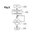
- An alternative mode shown in FIG. 5, runs such that the grindstone 42 spans the entire width of the Chopping drum 22 is moved until a constant distance made between shaft 32 and cutting edges of the knife 38 is.
- the controller 50 recognizes the output signal of the Knock sensor 50 whether there is a constant distance between shaft 32 and cutting edges of the knife 38 has been reached and accordingly the grinding process can be ended.
- grinding stone 42 can be delivered, if at one or more points of the chopper drum 22 from Knock sensor no contact between grindstone 42 and knives 38 is proven. The grinding process therefore takes place that after starting in step 120, the grindstone 42 in Move step 122 across the width of the chopper drum 22 becomes.
- step 124 it is checked whether the signal of the Knock sensor 50 is constant. If not, follow Step 122, otherwise the end in step 126.
- the control can before Finishing or a subsequent normal Grinding process again over the grindstone holder 40 move the width of the chopper drum 22 and through the Knock sensor 50 the distances between shaft 32 and cutting edges the knife 38 grasp. Is the form recorded here Cutting edges of the knife 38 are not satisfactory a new grinding process in the manner described above.
- FIG 6 is a second embodiment of an inventive Grinding device reproduced. Share that to those of correspond to the first embodiment are the same Assigned reference numerals. There is a difference in terms of Measuring device, which instead of the knock sensor 50 on the Grinding stone holder 40 a magnetically working sensor 56 on the shear bar 46.
- the shear bar 46 is through Actuators 58, 60 movable relative to the chopper drum 22.
- the Actuators 58, 60 are preferred by controller 52 controlled synchronously to the shear bar 46 in a To spend chopping operation suitable position.
- the magnetic Working sensor 56 provides information about the distance between the shear bar 46 and one on the shear bar 46 rotating cutting edge of a knife 38 ready.
Landscapes
- Life Sciences & Earth Sciences (AREA)
- Environmental Sciences (AREA)
- Constituent Portions Of Griding Lathes, Driving, Sensing And Control (AREA)
- Finish Polishing, Edge Sharpening, And Grinding By Specific Grinding Devices (AREA)
Abstract
Description
- Fig. 1
- schematische Ansichten von Häckseltrommeln mit Messern mit unterschiedlichen Formen,
- Fig. 2
- eine Erntemaschine mit einer Häckseltrommel mit Schleifvorrichtung in Seitenansicht und in schematischer Darstellung,
- Fig. 3
- eine Vorderansicht einer ersten Ausführungsform einer Schleifvorrichtung,
- Fig. 4
- ein Flussdiagramm, das einen Schleifvorgang illustriert,
- Fig. 5
- ein Flussdiagramm, das einen anderen Schleifvorgang illustriert, und
- Fig. 6
- eine Vorderansicht einer zweiten Ausführungsform einer Schleifvorrichtung.
Claims (14)
- Schleifvorrichtung, mit einem Schleifstein (42) zum Schleifen mindestens eines Messers (38) einer Häckseleinrichtung, einer Bewegungseinrichtung (48) zum Bewegen des Schleifsteins (42), einer Messeinrichtung zur Bereitstellung eines Signals, das eine Information über die Form der Schneidkante des Messers (38) enthält, und einer Steuerung (52), die die Bewegungseinrichtung (48) in Abhängigkeit von dem von der Messeinrichtung bereitgestellten Signal steuert, dadurch gekennzeichnet, dass die Steuerung (52) die Bewegungseinrichtung (48) derart steuert, dass die Schneidkante des Messers (38) in eine vorbestimmte und/oder vorgebbare Sollform gebracht wird.
- Schleifvorrichtung nach Anspruch 1, dadurch gekennzeichnet, dass die Steuerung (52) die von der Messeinrichtung bereitgestellten Informationen über die Form der Schneidkante des Messers (38) mit der Sollform vergleicht und/oder prüft, ob die Sollform erreicht ist.
- Schleifvorrichtung nach Anspruch 1 oder 2, dadurch gekennzeichnet, dass die Häckseleinrichtung eine Häckseltrommel (22) und daran befestigte Messer (38) aufweist, dass die Häckseltrommel (22) auf einer sich beim Schleifen drehenden Welle (32) angeordnet ist, und dass die Messeinrichtung eine Information über den Radius des Hüllkreises der Messer (38) bereitstellt.
- Schleifvorrichtung nach Anspruch 3, dadurch gekennzeichnet, dass die Steuerung (52) die Bewegungseinrichtung (48) derart steuert, dass sich eine im wesentlichen zur Welle (32) parallele Schneidkante der Messer (38) bzw. eine über die Breite der Häckseltrommel (22) betrachtet leicht konkave Form der Schneidkanten der Messer (38) ergibt.
- Schleifvorrichtung nach einem der Ansprüche 1 bis 4, dadurch gekennzeichnet, dass die Bewegungseinrichtung (48) eingerichtet ist, den Schleifstein (42) über die Breite der Häckseltrommel (22) zu bewegen und/oder den Schleifstein (42) zum Messer (38) zuzustellen.
- Schleifvorrichtung nach einem der Ansprüche 1 bis 5, dadurch gekennzeichnet, dass die Steuerung (52) die Bewegungseinrichtung (48) derart steuert, dass der Schleifstein (42) zeitlich nicht linear über die Breite der Häckseleinrichtung bewegt wird.
- Schleifvorrichtung nach Anspruch 6, dadurch gekennzeichnet, dass die Steuerung (52) die Bewegungseinrichtung (48) derart steuert, dass der Schleifstein (42) jeweils an einer Position stehen bleibt, bis die Messeinrichtung ein dieser Position zugeordnetes Ausgangssignal erzeugt, das einem bestimmten Radius des Hüllkreises der Schneidkanten der Messer (38) entspricht, und dass der Schleifstein (42) danach von der Bewegungseinrichtung (48) weiter über die Breite der Häckseleinrichtung bewegt wird.
- Schleifvorrichtung nach einem der Ansprüche 1 bis 6, dadurch gekennzeichnet, dass die Steuerung (52) die Bewegungseinrichtung (48) derart steuert, dass sie den Schleifstein (42) kontinuierlich über die Breite der Häckseleinrichtung verfährt.
- Schleifvorrichtung nach Anspruch 7 oder 8, dadurch gekennzeichnet, dass ein weiterer Schleifvorgang durchgeführt wird, bei dem der Schleifstein (42) zugestellt wird, wenn die Sollform des Messers (38) erzielt ist.
- Schleifvorrichtung nach einem der vorhergehenden Ansprüche, dadurch gekennzeichnet, dass die Steuerung (52) ein Fehlersignal bereitstellt, wenn die Schneidkante eines Messers (38) einen Abstand von einer Welle (32) oder den Schneidkanten der anderen Messer (38) aufweist, der über einem Schwellenwert liegt.
- Schleifvorrichtung nach einem der vorhergehenden Ansprüche, dadurch gekennzeichnet, dass die Messeinrichtung eine Information über den Abstand zwischen dem Schleifstein (42) und der Schneidkante eines am Schleifstein (42) vorbeilaufenden Messers (38) erzeugt.
- Schleifvorrichtung nach Anspruch 11, dadurch gekennzeichnet, dass die Messeinrichtung einen am Schleifstein (42) oder an einer Schleifsteinhalterung (40) angeordneten Klopfsensor (50) umfasst.
- Schleifvorrichtung nach einem der Ansprüche 1 bis 10, dadurch gekennzeichnet, dass die Messeinrichtung einen an einer Gegenschneide (46) angeordneten Sensor, insbesondere einen Klopfsensor oder einen magnetisch arbeitenden Sensor (56) umfasst.
- Erntemaschine, insbesondere selbstfahrender oder gezogener Feldhäcksler, mit einer Häckseleinrichtung und einer Schleifvorrichtung nach einem der Ansprüche 1 bis 13.
Applications Claiming Priority (2)
| Application Number | Priority Date | Filing Date | Title |
|---|---|---|---|
| DE10035743A DE10035743A1 (de) | 2000-07-22 | 2000-07-22 | Schleifvorrichtung |
| DE10035743 | 2000-07-22 |
Publications (2)
| Publication Number | Publication Date |
|---|---|
| EP1174020A1 true EP1174020A1 (de) | 2002-01-23 |
| EP1174020B1 EP1174020B1 (de) | 2005-03-30 |
Family
ID=7649857
Family Applications (1)
| Application Number | Title | Priority Date | Filing Date |
|---|---|---|---|
| EP01115146A Expired - Lifetime EP1174020B1 (de) | 2000-07-22 | 2001-06-22 | Schleifvorrichtung |
Country Status (4)
| Country | Link |
|---|---|
| US (1) | US6503135B2 (de) |
| EP (1) | EP1174020B1 (de) |
| CA (1) | CA2353354C (de) |
| DE (2) | DE10035743A1 (de) |
Cited By (5)
| Publication number | Priority date | Publication date | Assignee | Title |
|---|---|---|---|---|
| EP1759574A3 (de) * | 2005-09-02 | 2007-11-07 | CLAAS Selbstfahrende Erntemaschinen GmbH | Vorrichtung und Verfahren zur Detektion von Körperschallschwingungen |
| DE102014221465A1 (de) | 2014-10-22 | 2016-04-28 | Deere & Company | Schleifeinrichtung |
| DE102020126099A1 (de) | 2020-10-06 | 2022-04-07 | Deere & Company | Schleifeinrichtung für eine mit einer Anzahl an Messern versehene Häckseltrommel eines Feldhäckslers |
| BE1028680B1 (de) * | 2020-10-29 | 2022-07-08 | Deere & Co | Steueranordnung für eine Schleifeinrichtung und eine Einrichtung zur Verstellung der Position einer Gegenschneide gegenüber einer Häckseleinrichtung eines Feldhäckslers |
| BE1029073A1 (de) | 2021-02-22 | 2022-08-25 | Deere & Co | Schleifeinrichtung für eine mit einer Anzahl an Messern versehene Häckseltrommel eines Feldhäckslers |
Families Citing this family (14)
| Publication number | Priority date | Publication date | Assignee | Title |
|---|---|---|---|---|
| FR2826894B1 (fr) * | 2001-07-04 | 2003-09-19 | Eastman Kodak Co | Procede de rectification et dispositif de controle d'un arbre de coupe |
| DE10357177A1 (de) * | 2003-12-06 | 2005-07-14 | Deere & Company, Moline | Schleifvorrichtung |
| DE102006025224A1 (de) * | 2006-05-29 | 2007-12-20 | Claas Selbstfahrende Erntemaschinen Gmbh | Landwirtschaftliche Erntemaschine |
| DE102007041470A1 (de) * | 2007-08-31 | 2009-03-05 | Hauni Maschinenbau Ag | Vorrichtung und Verfahren zum Schleifen von Schneidmessern |
| DE102010019852A1 (de) * | 2010-05-07 | 2011-11-10 | Knecht Maschinenbau Gmbh | Vorrichtung zum Schleifen von Handmessern |
| DE102011055851A1 (de) * | 2011-05-21 | 2012-11-22 | Claas Saulgau Gmbh | Verfahren zur Erkennung der Schärfe von Schneidkanten von Häckselmessern |
| DE102011103418A1 (de) * | 2011-06-06 | 2012-12-06 | Weber Maschinenbau Gmbh Breidenbach | Vorrichtung und Verfahren zum Schleifen von Rotationsmessern |
| EP3175952B1 (de) | 2011-06-06 | 2024-07-31 | Weber Food Technology GmbH | Vorrichtung und verfahren zum schleifen von rotationsmessern |
| US20130316770A1 (en) * | 2011-12-28 | 2013-11-28 | Agco Corporation | Knife-sharpening system for an infeed cutter of an agricultural impelment |
| DE102013101183A1 (de) * | 2013-02-07 | 2014-08-07 | Claas Selbstfahrende Erntemaschinen Gmbh | Landwirtschaftliche Arbeitsmaschine, insbesondere Feldhäcksler |
| EP2805603B1 (de) * | 2013-05-22 | 2017-01-11 | CLAAS E-Systems KGaA mbH & Co KG | Vorrichtung und Verfahren zur Überwachung der Schneidenschärfe |
| WO2017053502A1 (en) | 2015-09-24 | 2017-03-30 | Wolff Industries, Inc. | Systems and methods for conditioning blades |
| CN110786155A (zh) * | 2019-12-10 | 2020-02-14 | 山东理工大学 | 一种青贮机刀具间隙调节及自动磨刀装置 |
| CN115634758B (zh) * | 2022-12-26 | 2023-03-07 | 中国农业科学院农业环境与可持续发展研究所 | 一种带动磨刀结构的秸秆粉碎装置 |
Citations (6)
| Publication number | Priority date | Publication date | Assignee | Title |
|---|---|---|---|---|
| EP0335332A1 (de) * | 1988-03-28 | 1989-10-04 | Deere & Company | Feldhäcksler |
| DE4023114A1 (de) | 1989-08-11 | 1991-08-01 | Agritechnik Ing Betrieb | Verfahren zum feststellen der schaerfe von haeckselmessern |
| FR2676612A1 (fr) * | 1991-05-21 | 1992-11-27 | Ouest Motoculture | Dispositif d'affutage des couteaux du rotor d'ensileuse a mauis. |
| FR2683975A1 (fr) * | 1991-10-23 | 1993-05-28 | Claas Ohg | Dispositif de reglage d'une contre-lame. |
| EP0943888A2 (de) | 1998-03-20 | 1999-09-22 | Deere & Company | Einrichtung zum Überwachen des Abstandes zwischen zwei magnetisch leitenden Teilen beweglich relativ zueinander |
| DE19903153C1 (de) | 1999-01-27 | 2000-03-16 | Case Harvesting Sys Gmbh | Verfahren zum Feststellen der Schärfe von Häckselmessern |
Family Cites Families (4)
| Publication number | Priority date | Publication date | Assignee | Title |
|---|---|---|---|---|
| US5098027A (en) * | 1990-02-28 | 1992-03-24 | Ford New Holland, Inc. | Automatic knife sharpening system for forage harvesters |
| US5103622A (en) | 1991-02-11 | 1992-04-14 | Ford New Holland, Inc. | Method and apparatus for maintaining cylindrical profile of forage harvester cutterheads |
| GB9506692D0 (en) * | 1995-03-31 | 1995-05-24 | New Holland Belguim Nv | Automatic knife sharpening method for forage harvesters |
| DE19910758A1 (de) * | 1999-03-11 | 2000-09-14 | Deere & Co | Schleifvorrichtung |
-
2000
- 2000-07-22 DE DE10035743A patent/DE10035743A1/de not_active Withdrawn
-
2001
- 2001-06-05 US US09/873,523 patent/US6503135B2/en not_active Expired - Lifetime
- 2001-06-22 EP EP01115146A patent/EP1174020B1/de not_active Expired - Lifetime
- 2001-06-22 DE DE50105754T patent/DE50105754D1/de not_active Expired - Lifetime
- 2001-07-20 CA CA002353354A patent/CA2353354C/en not_active Expired - Fee Related
Patent Citations (6)
| Publication number | Priority date | Publication date | Assignee | Title |
|---|---|---|---|---|
| EP0335332A1 (de) * | 1988-03-28 | 1989-10-04 | Deere & Company | Feldhäcksler |
| DE4023114A1 (de) | 1989-08-11 | 1991-08-01 | Agritechnik Ing Betrieb | Verfahren zum feststellen der schaerfe von haeckselmessern |
| FR2676612A1 (fr) * | 1991-05-21 | 1992-11-27 | Ouest Motoculture | Dispositif d'affutage des couteaux du rotor d'ensileuse a mauis. |
| FR2683975A1 (fr) * | 1991-10-23 | 1993-05-28 | Claas Ohg | Dispositif de reglage d'une contre-lame. |
| EP0943888A2 (de) | 1998-03-20 | 1999-09-22 | Deere & Company | Einrichtung zum Überwachen des Abstandes zwischen zwei magnetisch leitenden Teilen beweglich relativ zueinander |
| DE19903153C1 (de) | 1999-01-27 | 2000-03-16 | Case Harvesting Sys Gmbh | Verfahren zum Feststellen der Schärfe von Häckselmessern |
Cited By (7)
| Publication number | Priority date | Publication date | Assignee | Title |
|---|---|---|---|---|
| EP1759574A3 (de) * | 2005-09-02 | 2007-11-07 | CLAAS Selbstfahrende Erntemaschinen GmbH | Vorrichtung und Verfahren zur Detektion von Körperschallschwingungen |
| DE102014221465A1 (de) | 2014-10-22 | 2016-04-28 | Deere & Company | Schleifeinrichtung |
| DE102014221465B4 (de) | 2014-10-22 | 2023-03-16 | Deere & Company | Schleifeinrichtung |
| DE102020126099A1 (de) | 2020-10-06 | 2022-04-07 | Deere & Company | Schleifeinrichtung für eine mit einer Anzahl an Messern versehene Häckseltrommel eines Feldhäckslers |
| BE1028680B1 (de) * | 2020-10-29 | 2022-07-08 | Deere & Co | Steueranordnung für eine Schleifeinrichtung und eine Einrichtung zur Verstellung der Position einer Gegenschneide gegenüber einer Häckseleinrichtung eines Feldhäckslers |
| BE1029073A1 (de) | 2021-02-22 | 2022-08-25 | Deere & Co | Schleifeinrichtung für eine mit einer Anzahl an Messern versehene Häckseltrommel eines Feldhäckslers |
| DE102021104158A1 (de) | 2021-02-22 | 2022-08-25 | Deere & Company | Schleifeinrichtung für eine mit einer Anzahl an Messern versehene Häckseltrommel eines Feldhäckslers |
Also Published As
| Publication number | Publication date |
|---|---|
| US6503135B2 (en) | 2003-01-07 |
| US20020009963A1 (en) | 2002-01-24 |
| CA2353354A1 (en) | 2002-01-22 |
| EP1174020B1 (de) | 2005-03-30 |
| CA2353354C (en) | 2005-11-08 |
| DE50105754D1 (de) | 2005-05-04 |
| DE10035743A1 (de) | 2002-04-04 |
Similar Documents
| Publication | Publication Date | Title |
|---|---|---|
| EP1174021B1 (de) | Schleifvorrichtung | |
| EP1174020B1 (de) | Schleifvorrichtung | |
| EP2764767B1 (de) | Landwirtschaftliche Erntemaschine, insbesondere Feldhäcksler | |
| EP1862061B1 (de) | Landwirtschaftliche Erntemaschine | |
| DE102013201633B3 (de) | Einrichtung zur Verstellung der Position einer Gegenschneide gegenüber einer Häckseleinrichtung | |
| DE19632977A1 (de) | Vorrichtung und Verfahren zur Einzugssteuerung eines Feldhäckslers | |
| BE1025031B1 (de) | Anordnung zur Erkennung des Verschleißgrades von Häckselmessern einer Häckseltrommel eines Feldhäckslers | |
| DE102004016089B4 (de) | Einrichtung zur Verstellung der Position einer Gegenschneide gegenüber einer Häckseleinrichtung | |
| EP2425705B1 (de) | Schneidvorrichtung | |
| DE19903153C1 (de) | Verfahren zum Feststellen der Schärfe von Häckselmessern | |
| BE1028679B1 (de) | Einrichtung zur Verstellung der Position einer Gegenschneide gegenüber einer Häckseleinrichtung | |
| DE102009004821A1 (de) | Feldhäcksler mit einstellungsgekoppelter Zuführ- und Gutbearbeitungseinrichtung und Betriebsverfahren dazu | |
| BE1028680B1 (de) | Steueranordnung für eine Schleifeinrichtung und eine Einrichtung zur Verstellung der Position einer Gegenschneide gegenüber einer Häckseleinrichtung eines Feldhäckslers | |
| BE1029073B1 (de) | Schleifeinrichtung für eine mit einer Anzahl an Messern versehene Häckseltrommel eines Feldhäckslers | |
| EP1537772B1 (de) | Häckselvorrichtung mit Schleifvorrichtung | |
| EP1145617B1 (de) | Schleifvorrichtung | |
| DE19910757A1 (de) | Schleifvorrichtung | |
| DE102014221465B4 (de) | Schleifeinrichtung | |
| DE102020126099A1 (de) | Schleifeinrichtung für eine mit einer Anzahl an Messern versehene Häckseltrommel eines Feldhäckslers | |
| DE19942400C1 (de) | Verfahren zum Einstellen des Schneidspaltes an Häckslern | |
| EP4122313A1 (de) | Verfahren zur bestimmung des verschleisszustandes einer an einem gegenschneideträger angeordneten gegenschneide sowie selbstfahrender feldhäcksler | |
| DE4431551C2 (de) | Brecher mit einem Gestell, in dem ein angetriebener, steinbrechender Rotor gelagert ist | |
| DE102016207565A1 (de) | Einrichtung zur Erfassung der Schärfe von Messern einer Erntemaschine zum Ernten von halmförmigem Erntegut | |
| BE1030161B1 (de) | Schleifeinrichtung | |
| EP4477048A1 (de) | Feldhäcksler |
Legal Events
| Date | Code | Title | Description |
|---|---|---|---|
| PUAI | Public reference made under article 153(3) epc to a published international application that has entered the european phase |
Free format text: ORIGINAL CODE: 0009012 |
|
| AK | Designated contracting states |
Kind code of ref document: A1 Designated state(s): AT BE CH CY DE DK ES FI FR GB GR IE IT LI LU MC NL PT SE TR Kind code of ref document: A1 Designated state(s): BE DE |
|
| AX | Request for extension of the european patent |
Free format text: AL;LT;LV;MK;RO;SI |
|
| 17P | Request for examination filed |
Effective date: 20020723 |
|
| AKX | Designation fees paid |
Free format text: BE DE |
|
| 17Q | First examination report despatched |
Effective date: 20040323 |
|
| GRAP | Despatch of communication of intention to grant a patent |
Free format text: ORIGINAL CODE: EPIDOSNIGR1 |
|
| GRAS | Grant fee paid |
Free format text: ORIGINAL CODE: EPIDOSNIGR3 |
|
| GRAA | (expected) grant |
Free format text: ORIGINAL CODE: 0009210 |
|
| AK | Designated contracting states |
Kind code of ref document: B1 Designated state(s): BE DE |
|
| REF | Corresponds to: |
Ref document number: 50105754 Country of ref document: DE Date of ref document: 20050504 Kind code of ref document: P |
|
| REG | Reference to a national code |
Ref country code: IE Ref legal event code: FG4D Free format text: LANGUAGE OF EP DOCUMENT: GERMAN |
|
| PLBE | No opposition filed within time limit |
Free format text: ORIGINAL CODE: 0009261 |
|
| STAA | Information on the status of an ep patent application or granted ep patent |
Free format text: STATUS: NO OPPOSITION FILED WITHIN TIME LIMIT |
|
| 26N | No opposition filed |
Effective date: 20060102 |
|
| PGFP | Annual fee paid to national office [announced via postgrant information from national office to epo] |
Ref country code: BE Payment date: 20170627 Year of fee payment: 17 |
|
| REG | Reference to a national code |
Ref country code: BE Ref legal event code: MM Effective date: 20180630 |
|
| PG25 | Lapsed in a contracting state [announced via postgrant information from national office to epo] |
Ref country code: BE Free format text: LAPSE BECAUSE OF NON-PAYMENT OF DUE FEES Effective date: 20180630 |
|
| PGFP | Annual fee paid to national office [announced via postgrant information from national office to epo] |
Ref country code: DE Payment date: 20200630 Year of fee payment: 20 |
|
| REG | Reference to a national code |
Ref country code: DE Ref legal event code: R071 Ref document number: 50105754 Country of ref document: DE |