EP1173959B1 - Method and apparatus for estimating channel conditions in wireless communication systems - Google Patents
Method and apparatus for estimating channel conditions in wireless communication systems Download PDFInfo
- Publication number
- EP1173959B1 EP1173959B1 EP00928770A EP00928770A EP1173959B1 EP 1173959 B1 EP1173959 B1 EP 1173959B1 EP 00928770 A EP00928770 A EP 00928770A EP 00928770 A EP00928770 A EP 00928770A EP 1173959 B1 EP1173959 B1 EP 1173959B1
- Authority
- EP
- European Patent Office
- Prior art keywords
- signal
- received
- noise
- estimating
- certain amplitude
- Prior art date
- Legal status (The legal status is an assumption and is not a legal conclusion. Google has not performed a legal analysis and makes no representation as to the accuracy of the status listed.)
- Expired - Lifetime
Links
- 238000000034 method Methods 0.000 title claims abstract description 64
- 238000004891 communication Methods 0.000 title claims description 26
- 230000006870 function Effects 0.000 description 12
- 238000005562 fading Methods 0.000 description 10
- 230000008569 process Effects 0.000 description 5
- 238000010586 diagram Methods 0.000 description 4
- 238000013459 approach Methods 0.000 description 3
- 230000005540 biological transmission Effects 0.000 description 3
- 238000012545 processing Methods 0.000 description 3
- 230000008901 benefit Effects 0.000 description 2
- 230000001413 cellular effect Effects 0.000 description 2
- 230000001427 coherent effect Effects 0.000 description 2
- 230000000875 corresponding effect Effects 0.000 description 2
- 238000001514 detection method Methods 0.000 description 2
- 238000005259 measurement Methods 0.000 description 2
- 238000012935 Averaging Methods 0.000 description 1
- 238000007476 Maximum Likelihood Methods 0.000 description 1
- 206010033307 Overweight Diseases 0.000 description 1
- 239000000654 additive Substances 0.000 description 1
- 230000000996 additive effect Effects 0.000 description 1
- 238000003491 array Methods 0.000 description 1
- 239000000969 carrier Substances 0.000 description 1
- 239000000470 constituent Substances 0.000 description 1
- 230000001276 controlling effect Effects 0.000 description 1
- 230000002596 correlated effect Effects 0.000 description 1
- 230000001419 dependent effect Effects 0.000 description 1
- 238000005516 engineering process Methods 0.000 description 1
- 238000002156 mixing Methods 0.000 description 1
- 238000012986 modification Methods 0.000 description 1
- 230000004048 modification Effects 0.000 description 1
- 230000037361 pathway Effects 0.000 description 1
- 230000010363 phase shift Effects 0.000 description 1
- 239000004065 semiconductor Substances 0.000 description 1
- 230000035945 sensitivity Effects 0.000 description 1
- 238000004088 simulation Methods 0.000 description 1
- 238000001228 spectrum Methods 0.000 description 1
Images


Classifications
-
- H—ELECTRICITY
- H04—ELECTRIC COMMUNICATION TECHNIQUE
- H04L—TRANSMISSION OF DIGITAL INFORMATION, e.g. TELEGRAPHIC COMMUNICATION
- H04L1/00—Arrangements for detecting or preventing errors in the information received
- H04L1/004—Arrangements for detecting or preventing errors in the information received by using forward error control
- H04L1/0056—Systems characterized by the type of code used
- H04L1/0059—Convolutional codes
-
- H—ELECTRICITY
- H04—ELECTRIC COMMUNICATION TECHNIQUE
- H04L—TRANSMISSION OF DIGITAL INFORMATION, e.g. TELEGRAPHIC COMMUNICATION
- H04L1/00—Arrangements for detecting or preventing errors in the information received
- H04L1/004—Arrangements for detecting or preventing errors in the information received by using forward error control
- H04L1/0056—Systems characterized by the type of code used
- H04L1/0064—Concatenated codes
- H04L1/0066—Parallel concatenated codes
Definitions
- the invention relates to communication systems. More particularly, the invention relates to methods and apparatus for improving reception and decoding of signals encoded using turbo codes.
- CDMA code division multiple access
- CDMA modulation techniques can provide capacity improvements over other techniques, such as time division multiple access (TDMA) and frequency division multiple access (FDMA) based in part on CDMA's use of orthogonal functions or codes. Additionally, CDMA receivers employ Viterbi decoders that employ Viterbi algorithms to perform maximum likelihood decoding of received signals.
- TDMA time division multiple access
- FDMA frequency division multiple access
- CDMA receivers employ Viterbi decoders that employ Viterbi algorithms to perform maximum likelihood decoding of received signals.
- a new encoding scheme employing "turbo" codes employs a combination of two simple encoders that receive a block of K information bits, and which generate parity symbols from two simple recursive convolutional codes, each having a small number of states.
- the K information bits are sent uncoded, with the parity symbols, over a noisy channel.
- an interleaver permutes the original K information bits before inputting such bits to the second encoder.
- the permutation causes one encoder to produce low-weight code words, while the other encoder produces high-weight code words.
- the resulting code is similar to "random" block codes with K information bits. Random block codes are known to achieve Shannon-limit performance when K is large, but truly random block codes require a prohibitively costly and complex decoding algorithm.
- a pair of simple decoders employing iterative maximum a posteriori algorithms receive both the original K information bits, together with one of the sets of parity symbols from one of the two encoders.
- the decoders are individually matched to the simple codes, and each decoder sends an a posteriori likelihood estimate of the decoded bits to the other decoder, while using the corresponding estimates from the other decoder as an a priori likelihood.
- Uncommon information bits corrupted by the noisy channel are available to each decoder to minimize the a priori likelihoods, while the decoders use maximum a priori decoding algorithms, which requires the same number of states as the Viterbi algorithm.
- turbo codes may be found, for example, in " A Primer On Turbo Code Concepts," by B. Sklar, IEEE Communications Magazine, 35:12 (December 1997 ).
- turbo codes have the potential to improve information transmission over a noisy channel by a large amount, compared to classical Viterbi decoding, even results remarkably close to the theoretical Shannon-limit.
- idealized conditions at the receiver which are in practice, very difficult to approach.
- One troublesome idealized condition is that the receiver is presumed to know the signal and noise power on a per symbol basis. This can be particularly difficult because the signals are multiplied by information bits, which makes the means or averages of the signals zero, thus disallowing usual averaging procedures for estimating signal noise power.
- turbo encoding is much less attractive, if not worse, when compared to conventional Viterbi decoding of a convolutional code.
- the inventors have found, through experimentation, that classical techniques for estimating channel conditions induce a loss in performance because of the poor performance of such estimation techniques.
- the inventors have found a new set of techniques for signal and noise power estimation that apply not only to turbo codes, but to applications in other fields where such type of estimation is needed (e.g., power control in CDMA telecommunications systems, other concatenated coding schemes, etc.).
- Such new techniques estimate the signal to noise ratio in received signals, and importantly, provide estimations of signal and noise separately, and thereby provide important improvements over the method described in the Summers and Wilson article.
- one aspect of the invention provides initial estimates of signal and noise, such as by using an efficient curve fitting technique. Thereafter, the energy of received pilot symbols is used to provide a finer estimation of the signal and noise.
- FIG. 1 illustrates an exemplary cellular subscriber communication system 100, which uses multiple access techniques such as CDMA for communicating between users of user stations (e.g., mobile telephones) and cell-sites or base stations.
- a mobile user station 102 communicates with a base station controller 104 through one or more base stations 106a, 106b, etc.
- a fixed user station 108 communicates with the base station controller 104 , but through only one or more predetermined and proximate base stations, such as the base stations 106a and 106b.
- the base station controller 104 is coupled to and typically includes interface and processing circuitry for providing system control to the base stations 106a and 106b.
- the base station controller 104 may also be coupled to and communicate with other base stations 106a and 106b, and possibly even other base station controllers.
- the base station controller 104 is coupled to a mobile switching center 110, which in turn is coupled to a home location register 112.
- the base station controller 104 and the mobile switching center 110 compare registration signals received from the user stations 102 or 108 to data contained in the home location register 112, as is known in the art. Soft handoffs may occur between the base station controller 104 and other base station controllers, and even between the mobile switching center 110 and other mobile switching centers, as is known by those skilled in the art.
- the base station controller 104 When the system 100 processes telephone or data traffic calls, the base station controller 104 establishes, maintains and terminates the wireless link with the mobile station 102 and the fixed user station 108, while the mobile switching center 110 establishes, maintains and terminates communications with a public switched telephone network (PSTN). While the discussion below focuses on signals transmitted between the base station 106a and the mobile station 102, those skilled in the art will recognize that the discussion equally applies to other base stations, and to the fixed user station 108.
- PSTN public switched telephone network
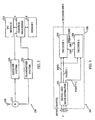
- FIG. 2 is a simplified block diagram of a portion of a transceiver 200 for use in either the base station 106a or 106b or the user stations 102 or 108 in the wireless communication system 100 of FIG. 1, under embodiments of the invention.
- the transceiver 200 includes a transmitter system 202 and receiver system 204 sharing an antenna 210 that transmits and receives signals to and from other transceivers 200.
- a duplexer 212 separates received signals from signals being transmitted by the transmitter system 202 and routes the received signals to the receiver system 204 .
- the receiver system 204 frequency shifts, demodulates and decodes the received signal.
- the receiver system 204 converts received signals to either baseband or an intermediate frequency and performs Walsh code demodulation, and also performs power and signal quality measurements.
- a control processor 216 provides much of the processing of the received signal, as described below.
- a memory 218 permanently stores routines performed by the control processor 216, and provides a temporary storage of data such as received frames.
- the transmitter 202 encodes, modulates, amplifies and up converts signals to be transmitted.
- the transmitter system 202 forms a forward traffic link data signal for re-transmission of received signals by the base stations 106a or 106b to the user stations 102 or 108. In another embodiment, the transmitter system 202 forms a reverse link traffic data signal for transmission from the user stations 102 or 108 back to the base station 106a.
- the receiver system 204 provides decoded received data to the user, and accepts information for transmission through the transmitter system 202 from the user, via an input/output (I/O) module 222 coupled to the control processor 216.
- I/O input/output
- a turbo decoder 300 which forms part of the receiver system 204, is shown.
- the decoder 300 may form part of the control processor 216 or the control processor may perform the operations described below for the decoder 300.
- the decoder 300 includes a signal and noise estimator 302 that receives an input channel having information and two parity signals or channels. The signal and noise estimator 302 separately estimates the power of the signal and noise in the received input channel, as described more fully below.
- a pair of simple decoders 304 and 306 each receive the information signal from the input channel. Additionally, the first decoder 304 (Decoder 1) receives the first parity symbol, while the second decoder 306 (Decoder 2) receives the second parity symbol.
- the decoder 300 (and the transceiver 200) may exist in the mobile station 102, and receive the information and parity symbols from the base station 106A .
- a typical turbo encoder at the base station 106A (not shown) provides a pair of simple encoders that generate parity signals from two simple recursive convolutional codes, where such codes have a small number of states.
- the parity symbols produced by the first encoder are received by the first decoder 304, while the parity symbols produced by the second encoder are received by the second decoder 306.
- the decoders 304 and 306 are matched to the codes of their respective encoders.
- the first decoder 304 provides an a posteriori likelihood estimate of decoded bits on the information channel to the second decoder 306 over line 308.
- the second decoder 306 does likewise over the line 310 for its corresponding estimate.
- the a posteriori estimates are used as a priori likelihoods for each decoder. Several iterations are performed until reaching a satisfactory convergence, at which point the final output of the likelihood estimates are provided.
- the signal and noise estimator 302 separately analyzes signal and noise on the received input channel to generate appropriate estimates.
- Equation (1) may be rewritten by replacing the amplitude A i with the square root of the energy per symbol ( i.e., E si ) .
- the signal and noise estimator 302 must provide separate estimates for the signal amplitude or energy E si and the noise variance ⁇ 2 . If the signal b i were always equal to one, the signal and noise estimator 302 could readily measure the sample mean and the sample variance. However, since ⁇ b i ⁇ is equal to ⁇ 1, then the mean is effectively zero.
- the signal and noise estimator 302 may use the sample mean of the magnitude of x i 's, under the following equations: E
- equation (5) stays relatively constant for the typical range of E s ⁇ encountered.
- the system may use equation (5) with no iterations to estimate E s .
- CDMA demodulation techniques typically combine symbols from various fingers, carriers or by weighting them by the pilot signal (explained more below).
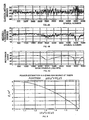
- FIG. 4C shows a reference curve of amplitude verses quadrature phase shift key (QPSK) symbols 1-5,000 in a Rayleigh fading environment with the decoder moving at a rate of 3 km/h.
- the demodulator in this example is demodulating under CDMA techniques ("CDMA 2000") in Direct Spread mode.
- FIG. 4A shows a typical method of estimating amplitude and noise using classical estimations of the mean of the received signal.
- FIG. 4B shows amplitude verses QPSK symbol under the above method, where noise ⁇ 2 and signal amplitude A are estimated separately.
- the previous embodiment suffers from subtracting two noisy quantities.
- the above fixed-point operator equation to solve for E s / ⁇ 2 has certain disadvantages in practical applications, namely, the iteration process might be slow to converge, and each step of the iteration requires computations for every sample. Thus, a straightforward method can be easier and quicker in computation time.
- Another problem with the above embodiment is that an acceptable beginning point for the iteration is difficult to find.
- equation (10) a simple curve fit may be used to inverse this function. The complexity of this computation is equivalent to the complexity of the above fixed-point method, but with only one step.
- a simple second order curve fit is described in the above article by Summers and Wilson.
- Such a curve fit provides the following: g E s ⁇ 2 ⁇ in dB ⁇ - 34.0516 ⁇ z 2 + 65.9548 ⁇ z - 23.6184
- the function g of equation (11) is not bijective, which means that for every z found under this equation, there is one and only one ratio E s / ⁇ 2 .
- FIG. 5 shows the function g for the ratio E ( x 2 )/ E (
- the variance may be found under known methods, such as those described in an article by M. Reed and J. Asenstorfer, entitled “A Novel Variance Estimator for Turbocode Decoding,” in Int'l Conf. Telecommunications, Melbourne, Australia, April 1997, pp. 173-178 .
- the mean SNR estimate will be less than the true SNR.
- Some bias occurs, due to the fact that deviations exist between the fit of the second-order polynomial estimate and the actual function of the sample averages.
- the curve fit does not apply for very small SNR, nor very large SNR.
- the SNR is very high, then the decoders 304 and 306 can readily decode the frame.
- the SNR is very low, then the frame is lost anyway. If the SNR is in-between, a good estimation of the SNR helps the decoders 304 and 306; so the curve estimates the SNR in the range of about -4 dB to 8 dB.
- the traffic channel does not need a very high signal to noise ratio; however, a good estimation of the energy of the traffic symbols and the associated noise is quite difficult to obtain with only the incoming uncoded bits: x i ⁇ E si ⁇ b i + n i It is even more difficult when the signal to noise ratio is low.
- FER frame error rate
- the energy of the traffic channel over the forward link sent by the base station 106 is changing by plus or minus half a dB after each power control command.
- the TIA/EIA/IS-95-A CDMA standard requires sixteen power control commands during each frame (with 50 frames per second), at 9600 kb/s, where the energy of the traffic channel transmitted during one power control bit group remains constant.
- the IS-95 standard, as well as other modulation schemes, employ a pilot channel for transmitting pilot symbols from each base station. The energy of the pilot symbols is constant for a given base station 106. As a consequence, the ratio between the pilot's energy and the traffic's energy is constant during one power control bit group.
- pilot symbols may be found, for example, in co-inventor, Dr. Holtzman's U.S. Patent Application No. 09/144,402 , entitled “Method and Apparatus for Reducing Amplitude Variations and Interference in Communications Signals, Such as in Wireless Communications Signals Employing Inserted Pilot Symbols," filed August 31,1998.
- equation (10) may be simplified by first determining a separate estimate of ⁇ , and then estimating E s from the top half of equation (10) using an estimate of E
- E p is divided by the approximation of the ratio to find E s .
- E p is stronger than E s (typically a fifth of the base station power is allocated to E p ), and thus is more accurate.
- the second embodiment described above uses first an approximation of equation (10). Second, the received energy of pilot symbols and the ratio between the pilot's and the traffic's channel energy provide a finer estimation.
- the signal and noise estimator 302 receives a sample of the incoming traffic signal. Such a sample is greater than or equal to one symbol, and can be a frame or a power control group.
- the signal and noise estimator 302 fits a stored curve to the traffic channel sample.
- the stored curve may be, for example, the curve of FIG. 5.
- Such a curve may be stored in the memory 218, and the receiver system 204 or control processor 216 may access such a curve for the appropriate curve fitting.
- the signal and noise estimator 302 determines that the initial estimate of the energy per symbol E s of the traffic channel, and determines the estimate of the noise variance of ⁇ .
- step 608 the signal and noise estimator 302 estimates the ratio of the energy of the pilot versus the energy of the symbol using the received pilot channel sample.
- the ratio in step 608 may estimated as noted above, where the current ratio is calculated as follows: the current ratio is equal to ⁇ half the previous ratio if the current ratio is higher or lower than the previous ratio, respectively.
- step 610 the signal and noise estimator 302 determines improved for E s and ⁇ from the ratio E p / E s . Thereafter, the routine 600 loops back to step 602 where another sample is received and processed.
- routine 600 and other functions and methods described above may be performed by the estimator 302 and/or the control processor 216, where the estimator 302 is implemented by a custom ASIC, by a digital signal processing integrated circuit, through conventional logic circuit elements or through software programming of a general purpose computer or microprocessor (e.g ., the control processor 218 ).
- teachings provided herein of the invention can be applied to other communication systems, not necessarily the exemplary communication system described above.
- the invention has been generally described above as being employed in the CDMA communication system 100, the invention may be applied to other digital or analog communication systems, particularly concatenated encoding schemes.
Landscapes
- Engineering & Computer Science (AREA)
- Computer Networks & Wireless Communication (AREA)
- Signal Processing (AREA)
- Mobile Radio Communication Systems (AREA)
- Noise Elimination (AREA)
- Reduction Or Emphasis Of Bandwidth Of Signals (AREA)
- Transceivers (AREA)
- Error Detection And Correction (AREA)
- Cable Transmission Systems, Equalization Of Radio And Reduction Of Echo (AREA)
Applications Claiming Priority (3)
| Application Number | Priority Date | Filing Date | Title |
|---|---|---|---|
| US301813 | 1999-04-29 | ||
| US09/301,813 US6393257B1 (en) | 1999-04-29 | 1999-04-29 | Wireless communications receiver and decoder for receiving encoded transmissions, such as transmissions using turbo codes, and estimating channel conditions |
| PCT/US2000/012028 WO2000067439A1 (en) | 1999-04-29 | 2000-05-01 | Estimation method, receiver and decoder, of channel conditions in wireless communications |
Publications (2)
| Publication Number | Publication Date |
|---|---|
| EP1173959A1 EP1173959A1 (en) | 2002-01-23 |
| EP1173959B1 true EP1173959B1 (en) | 2007-06-20 |
Family
ID=23165004
Family Applications (1)
| Application Number | Title | Priority Date | Filing Date |
|---|---|---|---|
| EP00928770A Expired - Lifetime EP1173959B1 (en) | 1999-04-29 | 2000-05-01 | Method and apparatus for estimating channel conditions in wireless communication systems |
Country Status (10)
Families Citing this family (20)
| Publication number | Priority date | Publication date | Assignee | Title |
|---|---|---|---|---|
| JP3535427B2 (ja) * | 1999-11-25 | 2004-06-07 | 松下電器産業株式会社 | 無線通信装置 |
| US6898254B2 (en) * | 2000-01-31 | 2005-05-24 | Texas Instruments Incorporated | Turbo decoder stopping criterion improvement |
| US6879648B2 (en) * | 2000-01-31 | 2005-04-12 | Texas Instruments Incorporated | Turbo decoder stopping based on mean and variance of extrinsics |
| WO2001061867A1 (fr) * | 2000-02-15 | 2001-08-23 | Kawasaki Steel Corporation | Turbodecodeur |
| KR100493150B1 (ko) * | 2000-04-10 | 2005-06-02 | 삼성전자주식회사 | 이동통신을 위한 폐루프 전송 다이버시티의 최적 가중치탐색장치 및 방법 |
| US6952561B1 (en) * | 2000-08-31 | 2005-10-04 | Lucent Technologies Inc. | Enhanced metric for bit detection on fading channels with unknown statistics |
| US7099334B2 (en) * | 2001-03-29 | 2006-08-29 | Nortel Networks Limited | ATM over MPLS connection establishment mechanism |
| US7184497B2 (en) * | 2001-05-04 | 2007-02-27 | Lucent Technologies Inc. | Method of estimating a signal-to-interference+noise ratio (SINR) |
| US7093180B2 (en) * | 2002-06-28 | 2006-08-15 | Interdigital Technology Corporation | Fast H-ARQ acknowledgement generation method using a stopping rule for turbo decoding |
| KR100686410B1 (ko) * | 2002-08-01 | 2007-02-28 | 삼성전자주식회사 | 이동 통신 시스템에서 트래픽 채널과 파일럿 채널간전력비 검출 장치 및 방법 |
| US20040209585A1 (en) * | 2003-04-17 | 2004-10-21 | Motorola, Inc. | Method and apparatus for determining an interference level on a fading channel |
| KR100566210B1 (ko) * | 2003-09-22 | 2006-03-29 | 삼성전자주식회사 | 무선 통신 시스템에서 채널 할당 장치 및 방법 |
| US7362801B2 (en) * | 2003-12-18 | 2008-04-22 | Lsi Logic Corporation | Method for accurate estimation of noise for data modems |
| CN100391107C (zh) * | 2003-12-25 | 2008-05-28 | 上海贝尔阿尔卡特股份有限公司 | 信道编码方法和装置以及信道译码方法和装置 |
| US7672383B2 (en) * | 2004-09-17 | 2010-03-02 | Qualcomm Incorporated | Noise variance estimation in wireless communications for diversity combining and log-likelihood scaling |
| UA88328C2 (ru) * | 2004-09-17 | 2009-10-12 | Квелкомм Инкорпорейтед | Оценка дисперсии шума в беспроводной связи для объединения разнесения и масштабирования в соответствии с логарифмической вероятностью |
| US7684473B2 (en) * | 2005-06-01 | 2010-03-23 | Qualcomm Incorporated | Receiver for wireless communication network with extended range |
| TW200816651A (en) * | 2006-09-25 | 2008-04-01 | Sunplus Technology Co Ltd | Decoding method and system of real-time wireless channel estimation |
| CN101179354B (zh) * | 2006-11-09 | 2011-11-16 | 凌阳科技股份有限公司 | 一种无线通道即时估测的解码方法及系统 |
| CN103873067B (zh) * | 2014-02-26 | 2017-04-05 | 东南大学 | 一种用于脉冲干扰信道下Turbo码的译码方法 |
Family Cites Families (4)
| Publication number | Priority date | Publication date | Assignee | Title |
|---|---|---|---|---|
| US4901307A (en) | 1986-10-17 | 1990-02-13 | Qualcomm, Inc. | Spread spectrum multiple access communication system using satellite or terrestrial repeaters |
| US5103459B1 (en) | 1990-06-25 | 1999-07-06 | Qualcomm Inc | System and method for generating signal waveforms in a cdma cellular telephone system |
| JPH1117760A (ja) * | 1997-06-24 | 1999-01-22 | Sony Corp | 受信装置及び送受信装置並びに通信方法 |
| DE19736676C1 (de) * | 1997-08-22 | 1998-12-10 | Siemens Ag | Verfahren zur Paketübertragung mit einem ARQ-Protokoll auf Übertragungskanälen in einem digitalen Übertragungssystem |
-
1999
- 1999-04-29 US US09/301,813 patent/US6393257B1/en not_active Expired - Lifetime
-
2000
- 2000-05-01 DE DE60035269T patent/DE60035269T2/de not_active Expired - Lifetime
- 2000-05-01 AT AT00928770T patent/ATE365414T1/de not_active IP Right Cessation
- 2000-05-01 BR BR0010011-0A patent/BR0010011A/pt not_active IP Right Cessation
- 2000-05-01 JP JP2000616177A patent/JP2003514408A/ja active Pending
- 2000-05-01 WO PCT/US2000/012028 patent/WO2000067439A1/en active Search and Examination
- 2000-05-01 AU AU46952/00A patent/AU4695200A/en not_active Abandoned
- 2000-05-01 CN CNB008068577A patent/CN1238999C/zh not_active Expired - Fee Related
- 2000-05-01 EP EP00928770A patent/EP1173959B1/en not_active Expired - Lifetime
- 2000-05-01 KR KR1020017013857A patent/KR100748286B1/ko not_active Expired - Fee Related
Non-Patent Citations (1)
| Title |
|---|
| None * |
Also Published As
| Publication number | Publication date |
|---|---|
| US6393257B1 (en) | 2002-05-21 |
| CN1238999C (zh) | 2006-01-25 |
| KR100748286B1 (ko) | 2007-08-09 |
| DE60035269T2 (de) | 2008-02-21 |
| WO2000067439A1 (en) | 2000-11-09 |
| CN1349699A (zh) | 2002-05-15 |
| BR0010011A (pt) | 2004-06-29 |
| HK1043894A1 (en) | 2002-09-27 |
| KR20020038577A (ko) | 2002-05-23 |
| ATE365414T1 (de) | 2007-07-15 |
| EP1173959A1 (en) | 2002-01-23 |
| AU4695200A (en) | 2000-11-17 |
| JP2003514408A (ja) | 2003-04-15 |
| DE60035269D1 (de) | 2007-08-02 |
Similar Documents
| Publication | Publication Date | Title |
|---|---|---|
| EP1173959B1 (en) | Method and apparatus for estimating channel conditions in wireless communication systems | |
| US6731700B1 (en) | Soft decision output generator | |
| US6904097B2 (en) | Method and apparatus for adaptive signaling in a QAM communication system | |
| EP1264456B1 (en) | Method and apparatus for combined soft-decision based interference cancellation and decoding | |
| US7277498B2 (en) | Mapping method of code word with QAM modulation | |
| US20020122510A1 (en) | Apparatus for and method of converting soft symbol information to soft bit information | |
| US6728323B1 (en) | Baseband processors, mobile terminals, base stations and methods and systems for decoding a punctured coded received signal using estimates of punctured bits | |
| US20040196935A1 (en) | Method and apparatus for iteratively improving the performance of coded and interleaved communication systems | |
| KR19990082874A (ko) | 다중 레벨 변조된 신호의 반복적 디코딩 방법 및 장치 | |
| US6359935B1 (en) | Method for iterative demodulation and decoding for a system with coding and differential demodulation | |
| WO2000033504A1 (en) | Noise characterization in a wireless communication system | |
| US20050220203A1 (en) | System & method for spreading on fading channels | |
| US20030081696A1 (en) | System and method for estimating signal to noise ratio | |
| Zhang et al. | Space-time coding for Rayleigh fading channels in CPM system | |
| US7418052B2 (en) | Iterative turbo decision feedback receiver | |
| Ortin et al. | Performance analysis of turbo decoding algorithms in wireless OFDM systems | |
| US20050163245A1 (en) | Data encoding for static MIMO channels | |
| KR100993461B1 (ko) | 데이터 신호 처리 방법, 컴퓨터 판독가능 저장 매체, 데이터 신호 처리 장치 및 룩업 테이블 | |
| US6999530B2 (en) | Using SISO decoder feedback to produce symbol probabilities for use in wireless communications that utilize turbo coding and transmit diversity | |
| KR100448487B1 (ko) | 인터리브된 라이시안 페이딩 채널에 적합한 비동기식 다중격자 부호화 연속 위상 변조기의 격자 부호화기 설계방법 | |
| Wu et al. | LLR optimization for iterative MIMO BICM receivers | |
| US7099414B2 (en) | Ordered decoding in wireless communications that utilize turbo coding and transmit diversity | |
| Chu et al. | Serial concatenation of STBC or dSTBC with convolutional codes or turbo codes for space-time correlated channels | |
| Matsumoto | Decoding performance of linear block codes using a trellis in digital mobile radio | |
| HK1043894B (en) | Estimation method, receiver and decoder, of channel conditions in wireless communications |
Legal Events
| Date | Code | Title | Description |
|---|---|---|---|
| PUAI | Public reference made under article 153(3) epc to a published international application that has entered the european phase |
Free format text: ORIGINAL CODE: 0009012 |
|
| 17P | Request for examination filed |
Effective date: 20011022 |
|
| AK | Designated contracting states |
Kind code of ref document: A1 Designated state(s): AT BE CH CY DE DK ES FI FR GB GR IE IT LI LU MC NL PT SE |
|
| AX | Request for extension of the european patent |
Free format text: AL;LT;LV;MK;RO;SI |
|
| RAP1 | Party data changed (applicant data changed or rights of an application transferred) |
Owner name: QUALCOMM INCORPORATED |
|
| 17Q | First examination report despatched |
Effective date: 20050408 |
|
| RTI1 | Title (correction) |
Free format text: METHOD AND APPARATUS FOR ESTIMATING CHANNEL CONDITIONS IN WIRELESS COMMUNICATION SYSTEMS |
|
| GRAP | Despatch of communication of intention to grant a patent |
Free format text: ORIGINAL CODE: EPIDOSNIGR1 |
|
| GRAS | Grant fee paid |
Free format text: ORIGINAL CODE: EPIDOSNIGR3 |
|
| GRAA | (expected) grant |
Free format text: ORIGINAL CODE: 0009210 |
|
| AK | Designated contracting states |
Kind code of ref document: B1 Designated state(s): AT BE CH CY DE DK ES FI FR GB GR IE IT LI LU MC NL PT SE |
|
| PG25 | Lapsed in a contracting state [announced via postgrant information from national office to epo] |
Ref country code: LI Free format text: LAPSE BECAUSE OF FAILURE TO SUBMIT A TRANSLATION OF THE DESCRIPTION OR TO PAY THE FEE WITHIN THE PRESCRIBED TIME-LIMIT Effective date: 20070620 Ref country code: CH Free format text: LAPSE BECAUSE OF FAILURE TO SUBMIT A TRANSLATION OF THE DESCRIPTION OR TO PAY THE FEE WITHIN THE PRESCRIBED TIME-LIMIT Effective date: 20070620 |
|
| REG | Reference to a national code |
Ref country code: GB Ref legal event code: FG4D |
|
| REG | Reference to a national code |
Ref country code: CH Ref legal event code: EP |
|
| REG | Reference to a national code |
Ref country code: IE Ref legal event code: FG4D |
|
| REF | Corresponds to: |
Ref document number: 60035269 Country of ref document: DE Date of ref document: 20070802 Kind code of ref document: P |
|
| PG25 | Lapsed in a contracting state [announced via postgrant information from national office to epo] |
Ref country code: SE Free format text: LAPSE BECAUSE OF FAILURE TO SUBMIT A TRANSLATION OF THE DESCRIPTION OR TO PAY THE FEE WITHIN THE PRESCRIBED TIME-LIMIT Effective date: 20070920 |
|
| PG25 | Lapsed in a contracting state [announced via postgrant information from national office to epo] |
Ref country code: AT Free format text: LAPSE BECAUSE OF FAILURE TO SUBMIT A TRANSLATION OF THE DESCRIPTION OR TO PAY THE FEE WITHIN THE PRESCRIBED TIME-LIMIT Effective date: 20070620 |
|
| NLV1 | Nl: lapsed or annulled due to failure to fulfill the requirements of art. 29p and 29m of the patents act | ||
| ET | Fr: translation filed | ||
| REG | Reference to a national code |
Ref country code: CH Ref legal event code: PL |
|
| PG25 | Lapsed in a contracting state [announced via postgrant information from national office to epo] |
Ref country code: BE Free format text: LAPSE BECAUSE OF FAILURE TO SUBMIT A TRANSLATION OF THE DESCRIPTION OR TO PAY THE FEE WITHIN THE PRESCRIBED TIME-LIMIT Effective date: 20070620 |
|
| PG25 | Lapsed in a contracting state [announced via postgrant information from national office to epo] |
Ref country code: ES Free format text: LAPSE BECAUSE OF FAILURE TO SUBMIT A TRANSLATION OF THE DESCRIPTION OR TO PAY THE FEE WITHIN THE PRESCRIBED TIME-LIMIT Effective date: 20071001 Ref country code: PT Free format text: LAPSE BECAUSE OF FAILURE TO SUBMIT A TRANSLATION OF THE DESCRIPTION OR TO PAY THE FEE WITHIN THE PRESCRIBED TIME-LIMIT Effective date: 20071120 Ref country code: NL Free format text: LAPSE BECAUSE OF FAILURE TO SUBMIT A TRANSLATION OF THE DESCRIPTION OR TO PAY THE FEE WITHIN THE PRESCRIBED TIME-LIMIT Effective date: 20070620 |
|
| PLBE | No opposition filed within time limit |
Free format text: ORIGINAL CODE: 0009261 |
|
| STAA | Information on the status of an ep patent application or granted ep patent |
Free format text: STATUS: NO OPPOSITION FILED WITHIN TIME LIMIT |
|
| PG25 | Lapsed in a contracting state [announced via postgrant information from national office to epo] |
Ref country code: GR Free format text: LAPSE BECAUSE OF FAILURE TO SUBMIT A TRANSLATION OF THE DESCRIPTION OR TO PAY THE FEE WITHIN THE PRESCRIBED TIME-LIMIT Effective date: 20070921 Ref country code: DK Free format text: LAPSE BECAUSE OF FAILURE TO SUBMIT A TRANSLATION OF THE DESCRIPTION OR TO PAY THE FEE WITHIN THE PRESCRIBED TIME-LIMIT Effective date: 20070620 Ref country code: IT Free format text: LAPSE BECAUSE OF FAILURE TO SUBMIT A TRANSLATION OF THE DESCRIPTION OR TO PAY THE FEE WITHIN THE PRESCRIBED TIME-LIMIT Effective date: 20070620 |
|
| 26N | No opposition filed |
Effective date: 20080325 |
|
| PG25 | Lapsed in a contracting state [announced via postgrant information from national office to epo] |
Ref country code: MC Free format text: LAPSE BECAUSE OF NON-PAYMENT OF DUE FEES Effective date: 20080531 |
|
| PG25 | Lapsed in a contracting state [announced via postgrant information from national office to epo] |
Ref country code: FI Free format text: LAPSE BECAUSE OF FAILURE TO SUBMIT A TRANSLATION OF THE DESCRIPTION OR TO PAY THE FEE WITHIN THE PRESCRIBED TIME-LIMIT Effective date: 20070620 |
|
| PG25 | Lapsed in a contracting state [announced via postgrant information from national office to epo] |
Ref country code: IE Free format text: LAPSE BECAUSE OF NON-PAYMENT OF DUE FEES Effective date: 20080501 |
|
| PG25 | Lapsed in a contracting state [announced via postgrant information from national office to epo] |
Ref country code: CY Free format text: LAPSE BECAUSE OF FAILURE TO SUBMIT A TRANSLATION OF THE DESCRIPTION OR TO PAY THE FEE WITHIN THE PRESCRIBED TIME-LIMIT Effective date: 20070620 |
|
| PG25 | Lapsed in a contracting state [announced via postgrant information from national office to epo] |
Ref country code: LU Free format text: LAPSE BECAUSE OF NON-PAYMENT OF DUE FEES Effective date: 20080501 |
|
| PGFP | Annual fee paid to national office [announced via postgrant information from national office to epo] |
Ref country code: FR Payment date: 20100525 Year of fee payment: 11 |
|
| PGFP | Annual fee paid to national office [announced via postgrant information from national office to epo] |
Ref country code: DE Payment date: 20100531 Year of fee payment: 11 |
|
| PGFP | Annual fee paid to national office [announced via postgrant information from national office to epo] |
Ref country code: GB Payment date: 20100401 Year of fee payment: 11 |
|
| REG | Reference to a national code |
Ref country code: DE Ref legal event code: R119 Ref document number: 60035269 Country of ref document: DE |
|
| REG | Reference to a national code |
Ref country code: DE Ref legal event code: R119 Ref document number: 60035269 Country of ref document: DE |
|
| GBPC | Gb: european patent ceased through non-payment of renewal fee |
Effective date: 20110501 |
|
| REG | Reference to a national code |
Ref country code: FR Ref legal event code: ST Effective date: 20120131 |
|
| PG25 | Lapsed in a contracting state [announced via postgrant information from national office to epo] |
Ref country code: FR Free format text: LAPSE BECAUSE OF NON-PAYMENT OF DUE FEES Effective date: 20110531 |
|
| PG25 | Lapsed in a contracting state [announced via postgrant information from national office to epo] |
Ref country code: GB Free format text: LAPSE BECAUSE OF NON-PAYMENT OF DUE FEES Effective date: 20110501 |
|
| PG25 | Lapsed in a contracting state [announced via postgrant information from national office to epo] |
Ref country code: DE Free format text: LAPSE BECAUSE OF NON-PAYMENT OF DUE FEES Effective date: 20111130 |