EP1173920B1 - Moteur lineaire a commutation de flux - Google Patents
Moteur lineaire a commutation de flux Download PDFInfo
- Publication number
- EP1173920B1 EP1173920B1 EP00920957A EP00920957A EP1173920B1 EP 1173920 B1 EP1173920 B1 EP 1173920B1 EP 00920957 A EP00920957 A EP 00920957A EP 00920957 A EP00920957 A EP 00920957A EP 1173920 B1 EP1173920 B1 EP 1173920B1
- Authority
- EP
- European Patent Office
- Prior art keywords
- stator
- magnets
- coils
- magnetic
- axis
- Prior art date
- Legal status (The legal status is an assumption and is not a legal conclusion. Google has not performed a legal analysis and makes no representation as to the accuracy of the status listed.)
- Expired - Lifetime
Links
- 230000004907 flux Effects 0.000 title description 18
- 230000005291 magnetic effect Effects 0.000 claims abstract description 38
- 239000000696 magnetic material Substances 0.000 claims abstract description 6
- 239000003302 ferromagnetic material Substances 0.000 claims description 4
- 230000006698 induction Effects 0.000 claims description 3
- 239000000463 material Substances 0.000 abstract description 2
- 238000005452 bending Methods 0.000 description 4
- 229910001209 Low-carbon steel Inorganic materials 0.000 description 3
- 238000009826 distribution Methods 0.000 description 3
- 230000005294 ferromagnetic effect Effects 0.000 description 3
- 229910052782 aluminium Inorganic materials 0.000 description 2
- XAGFODPZIPBFFR-UHFFFAOYSA-N aluminium Chemical compound [Al] XAGFODPZIPBFFR-UHFFFAOYSA-N 0.000 description 2
- 238000009434 installation Methods 0.000 description 2
- 230000005415 magnetization Effects 0.000 description 2
- 229920002994 synthetic fiber Polymers 0.000 description 2
- 241000192308 Agrostis hyemalis Species 0.000 description 1
- RYGMFSIKBFXOCR-UHFFFAOYSA-N Copper Chemical compound [Cu] RYGMFSIKBFXOCR-UHFFFAOYSA-N 0.000 description 1
- 230000005355 Hall effect Effects 0.000 description 1
- 230000006978 adaptation Effects 0.000 description 1
- 238000004140 cleaning Methods 0.000 description 1
- 210000001520 comb Anatomy 0.000 description 1
- 229910052802 copper Inorganic materials 0.000 description 1
- 239000010949 copper Substances 0.000 description 1
- 230000003247 decreasing effect Effects 0.000 description 1
- 230000001419 dependent effect Effects 0.000 description 1
- 230000001627 detrimental effect Effects 0.000 description 1
- 238000006073 displacement reaction Methods 0.000 description 1
- 230000009977 dual effect Effects 0.000 description 1
- 230000000694 effects Effects 0.000 description 1
- 238000001125 extrusion Methods 0.000 description 1
- 230000002045 lasting effect Effects 0.000 description 1
- 230000014759 maintenance of location Effects 0.000 description 1
- 238000004519 manufacturing process Methods 0.000 description 1
- 239000002923 metal particle Substances 0.000 description 1
- 230000036961 partial effect Effects 0.000 description 1
- 230000000135 prohibitive effect Effects 0.000 description 1
- 230000000717 retained effect Effects 0.000 description 1
- 230000002441 reversible effect Effects 0.000 description 1
- 238000005096 rolling process Methods 0.000 description 1
- 238000006467 substitution reaction Methods 0.000 description 1
- 238000004804 winding Methods 0.000 description 1
- 229910000859 α-Fe Inorganic materials 0.000 description 1
Images



Classifications
-
- H—ELECTRICITY
- H02—GENERATION; CONVERSION OR DISTRIBUTION OF ELECTRIC POWER
- H02K—DYNAMO-ELECTRIC MACHINES
- H02K41/00—Propulsion systems in which a rigid body is moved along a path due to dynamo-electric interaction between the body and a magnetic field travelling along the path
- H02K41/02—Linear motors; Sectional motors
- H02K41/03—Synchronous motors; Motors moving step by step; Reluctance motors
- H02K41/031—Synchronous motors; Motors moving step by step; Reluctance motors of the permanent magnet type
Definitions
- the invention relates to a linear motor as defined in the preamble of claim 1.
- linear motors consist of a moving element comprising several coils moving in front of one or two rows of permanent magnets carried by a rail.
- the magnets are arranged, with alternating poles, all along one of the inner faces of a non-magnetic profile, for example aluminum, the succession of magnets defining a periodical structure step.
- the mobile unit consists of two coils provided with wipers for their DC power supply switched by two tracks arranged on the opposite inner face of the profile. The coils are shifted by a quarter of a step and supplied with phase quadrature.
- the mobile assembly consists of three coils shifted by a third of steps and powered by currents out of phase by 120 °.
- the mobile assembly consisting of three coils, overlaps the fixed magnets arranged in the plane of symmetry of a U-shaped section.
- the engine described in the patent EP 0 667 991 overcomes these disadvantages.
- the guide tube in which the moving element moves has no longer any magnets, but is itself made of ferromagnetic material and is cut in such a way as to have stator poles arranged in two opposite rows, the poles of a row being linearly offset relative to the poles of the other row.
- Each phase of the mobile unit comprises an inductor winding surrounding three armatures between which are disposed two permanent magnets of opposite polarities magnetized in the moving direction of the moving element.
- stator and mobile poles are arranged so that in a first of two positions of conjunction of the armatures, two first mobile poles belonging to each respectively at one of the inductors coincides with two stator poles belonging to two rows of different stator poles, while the other two mobile poles are offset with respect to the stator poles, whereas in the second of the two conjunction positions, the two other mobile poles coincide in turn with stator poles, the first two mobile poles being in turn offset with respect to the stator poles.
- the coil is traversed by a magnetic flux coming half from one of the magnets and half from the other magnet.
- the tubular shape of the stator makes its manufacture complex with regard to the precision necessary to reduce the value of the gap.
- the mechanical connection of the moving equipment to the driven object requires splitting the stator tube on one side, over its entire length, which affects its magnetic efficiency.
- the forces applied to the pole pieces of the armature are asymmetrical, resulting in one or more torsion torques on the moving equipment. This disadvantage makes it necessary to considerably stiffen the structure and / or to increase the gap.
- the magnetic leakage existing between the moving element and the uncut sides of the stator tube degrade the performance of the engine.
- the stator tube opposes bending operations that requires the realization of direct actuators, even in the case of a high radius of curvature.
- the object of the present invention is to overcome the abovementioned disadvantages, that is to say to increase the magnetic efficiency of the ferromagnetic poles of the guide element, to reduce magnetic leakage and to make it possible to produce curves by bending. of the guide element.
- linear motor according to the invention is characterized by the characteristics defined in the characterizing part of claim 1.
- the use in the guide element of magnetically independent ferromagnetic poles makes it possible to design a more easily bendable guiding element and / or to guarantee the positioning of the poles in a non-magnetic profile, and whose precision of obtaining, by die or extrusion, is incomparably greater than that of the folding of magnetic sheets according to the prior art.
- the poles of the guide element are preferably arranged in pairs, on either side of the axis of the guide tube and the size of the permanent magnets, measured along their magnetic axis, corresponds to the distance separating two stator poles. opposed. This arrangement has the advantage of eliminating the torsional torque on the crew.
- the guide tube consists of a U-shaped profile
- linear motors with fixed magnets it is possible to mechanically connect a moving assembly to a driven object without prejudice to performance.
- the forces on the moving equipment are perfectly symmetrical so that there is no torque. Light guidance is therefore sufficient to keep the movable assembly in a central position in the guide tube during its movement.
- nothing prevents the two or three phases are articulated either by a ball joint, or simply by exploiting the connection between the pairs of alternating magnets in direct contact, if it is the variant 1
- a slight gap between two phases created by a central pin allows a rotation of one phase relative to the other.
- two neighboring induction coils are connected by two magnets of opposite polarity.
- the switching of the current in the induction coils can be ensured by an ac or dc supply, as described in the prior art, in particular in the patent. EP 0 667 991 .
- the switching can be ensured by conducting tracks of adequate shape, as described in the patent EP 0 161 677 or be provided by a switching device mounted on the moving equipment, as described in the patent EP 0 667 991 .
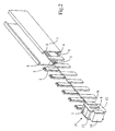
- the figure 1 is a perspective view of a section of a stator tube in which a moving element of which a single phase has been represented, according to variant 1.
- the figure 2 is a burst of the figure 1 .
- the figure 3 is an end view of the figure 1 , along the axis of the stator tube.
- FIGS. 4A to 4D illustrate the principle of switching the flow in one phase.
- the figure 5 shows schematically, for a three-phase motor in which each phase is provided with two distinct permanent magnets, a dynamic sequence of successive positions shifted by 1/6 of steps and the corresponding distribution of the flow in the three phases.
- the figure 6 is a similar representative view for a three-phase motor in which the phases have a permanent magnet in common.
- the figure 7 is a front view, in a plane parallel to that of the stator pads, of a moving element according to a second embodiment
- the Figures 8a to 8e represent the mobile crew of the figure 7 and the stator pads, in five successive positions of the moving equipment.
- the figure 9a represents a simplified embodiment, with an arrangement of the stator pads on a single face of the stator tube.
- the figure 9b illustrates the mirror effect obtained in the execution mode according to the figure 9a .
- the figure 10 represents a two-phase embodiment, according to variant 2, seen from the front in a plane parallel to that of the pads.
- the Figures 11a to 11c represent the mobile crew of the figure 10 and the stator pads, in three successive positions of the moving equipment.
- the figure 12 represents a variant of the arrangement of the stator blocks used in figure 11 .
- the motor shown comprises a stator tube 1 consisting of a non-magnetic guide section U rectangular section, for example aluminum. It could also be made of synthetic material, because it only serves as support for the stator poles consisting of platelets or rectangular pads 2 made of ferromagnetic material, for example mild steel. These plates 2 are retained by tight engagement in pairs of opposite grooves 3, 4 formed in the section 1 so as to be fixed against the inner faces of the two opposite parallel flanges of the U-shaped section. The plates 2 are positioned in pairs, such that the two plates of a pair are located opposite each other, symmetrically with respect to the axis of the profile 1. The successive pairs of plates 2 are equidistant and spaced apart from each other by a distance defining the pitch of the motor. In its transverse wall, the tube 1 furthermore has two additional grooves 5 and 6 for guiding the mobile equipment, as will be described later. These grooves 5 and 6 may be coated with a material facilitating the sliding of the moving element.
- the mobile equipment comprises two or three phases, such as the phase P1 represented in Figures 1 to 3 each of these phases consisting, in principle, of a coil 7 whose axis is perpendicular to the plane of the stator poles 2, this coil surrounding a core 8 of magnetic material constituting the armature.
- a coil 7 whose axis is perpendicular to the plane of the stator poles 2, this coil surrounding a core 8 of magnetic material constituting the armature.
- At the two ends of the coil 7, are fixed two rectangular plates 11 and 12 of non-magnetic material, preferably synthetic material, cooperating with the attachment of the permanent magnets 9 and 10.
- the core 8 and the permanent magnets 9 and 10 substantially have the same square section seen along the axis of the stator tube 1 and they are aligned along this axis. Viewed from the side, the core 8 and the magnets 9 and 10 have a rectangular section of width that can vary according to the executions.
- a two-phase mobile unit consisting of two phases such as P1 juxtaposed and a mobile three-phase and consisting of three phases such as P1 juxtaposed.
- the moving equipment is guided in the tube 1 by its two flanges 11 and 12 sliding in the grooves 5 and 6.
- the distance between the permanent magnets 9 and 10 or the core 8 and the stator poles 2 defines two air gaps e1 and e2.
- FIGS 4A to 4D illustrate the principle of the engine according to the invention, in its variant 1.
- the core 8 is located between a pair of stator poles 2, the neighboring pairs being located at such distances that the permanent magnets 9 and 10 are not engaged between these neighboring pairs.
- the magnetic fields of the two permanent magnets 9 and 10 tend to close through the stator poles 2 adjacent the core 8 and through the core 8. These two fields being equal and opposite, the magnetic flux in the core 8 is zero.
- the displacement of the coil between the magnetic parts 2 thus makes it possible to obtain an alternating electromotive force.
- the field of the magnet 9 at the Figure 4B and that of the magnet 10 to the figure 4D produces an undesirable flow in the core 8 which constitutes a magnetic loss.
- the distance between the poles of the magnet 9 at the Figure 4B and the ends of the core 8 on the one hand and the stator pole pieces 2 through which the main flow passes is, however, relatively large, so that the loss is very small, unlike what happens in the structure according to the patent.
- EP 0 667 991 The use of beveled studs on the edges facing each other makes it possible to further limit the magnetic losses.
- a three-phase motor is shown schematically at the figure 5 . It consists of three phases P1, P2 and P3 whose axes of the coils are respectively shifted by 1/3 of steps and 2/3 of steps relative to the stator pitch defined by the distance between two pairs of successive stator poles. The distance between the axes of two neighboring coils is therefore equal to 4/3 of steps.
- the coil axes would be offset by 1 ⁇ 4 steps relative to the stator pitch, respectively. It is understood that these offsets are given to a whole number of steps, and that it is possible to add or subtract a half-step, simply by reversing the current in the coil concerned.
- the figure 5 represents a dynamic sequence of the six positions shifted by 1/6 of steps and the corresponding distribution of the flux in the three phases.
- the signs +, -, o on the right of each sequence indicate the presence of a flow in the nucleus of each phase and its meaning, in the absence of current.
- - / + / o means that in phase P1 there is a "negative” flow directed downwards, for P2 a "positive” flow directed upwards and for P3 a zero flow, and thus of after.
- each phase can be equipped with a pair of sliding contacts moving on printed copper power supply tracks on an insulating support mounted in the bottom of the stator tube 1, that is to say between the grooves 5 and 6. These tracks are DC powered and switching can be provided by the nested slot form of the two tracks as shown and described in the patent. EP 0 161 677 .
- stator tube makes it possible without any other to make curves by bending the tube 1.
- the three phases of the motor represented in FIG. figure 5 can be articulated to each other so as to facilitate the taking of curve.
- This articulation 14 can be done by a ball joint or simply by exploiting the magnetic connection between the pairs of alternating magnets in direct contact, leaving a slight gap between two neighboring phases, air gap caused by a central pin allowing a rotation of one phase relative to the other.
- figure 6 represents a sequence in a similar way to the figure 5 .
- the magnets 9 and 10 connecting two phases to each other are replaced by a common magnet 13 whose direction of magnetization is respectively opposite to the magnetization direction of the nearest external magnet, the polarities of the magnets 13 being therefore opposed to each other, as is apparent from the figure 6 .
- To find an operation close to that of the execution mode represented in FIG. figure 5 it is necessary to reverse the connections of the coil of the phase P2, as is apparent from the flow distribution indicated for each of the positions of the sequence. It is clear that this arrangement with a common magnet avoids a large leakage flux between adjacent directly polarized magnets in the opposite direction.
- FIG. 7 and the Figures 8a to 8e show a device with moving two-phase, seen this time from the front, in a plane parallel to that of the pads.
- the magnets 9 are here cylindrical, each of the previous rectangular magnets being replaced by a pair of magnets, crimped in a housing 15.
- dark side corresponds to a North pole.
- the coils 7 ' are also cylindrical, as are their cores 8', but advantageously on each side of each coil-core assembly is a polar expansion 16, elongated in a direction perpendicular to the movement. This ensures the dual function of collecting the flux transmitted by the pads 2, and mechanical retention of the coil in the housing 15.
- the figure 8a represents the mobile equipment facing a row of stator pads 2, in an initial position.
- the studs 2 here have an exaggerated height: it suffices amply that they cover the magnets, and any unnecessary height results in an increase of the magnet magnetic leaks stud.
- the coil of the phase P1 is, ideally, completely traversed by the flow of the South magnets located on its right, while the North magnets to the left see their flow to close by the plate 17 of the left end. At the same time, the flux in phase P2 is zero.
- the figure 10 now represents a mobile unit according to the second variant of the invention. Magnets of the same polarity are arranged this time on the same side of the plane defined by the axis of the coils and the axis of the stator tube. If we take as orientations those defined by the sheet, we say that the magnetic flux which on average previously circulated horizontally, coming from the magnets located on the left or on the right of the coil, now circulates on average vertically, coming from the magnets located either at above or below the coil. As before, it is the arrangement of the stator blocks that favors one or the other direction of flow of the flow resulting in the core.
- variant 2 is sufficiently close to that of variant 1 to be directly illustrated on a two-phase embodiment, here particularly compact in the direction of movement.
- the two coils 7 are separated by three quarters of stator pitch.
- Polar expansion is not used on the cores 8 of the coils.
- Two lateral flow closure elements 17 are used, here in cylindrical form.
- FIGS. 11a to 11c illustrate the operation of this variant 2 in the presence of stator pads 2 ".
- stator pads 2 These have a T-shape which minimizes pin-pad leakage, as would also a triangular shape, and are again arranged in pairs, symmetrical to On either side of the plane parallel to the studs and containing the axis of the stator tube
- stator pins 2 are now two pairs of stator pins 2 "in steps: the studs are oriented alternately upwards and downwards every half-step .
- the coil of the phase P1 is, ideally, completely traversed by the flow of the South magnets located below, while the North magnet at the top left sees its flow partially close by the auxiliary cylinder 17 of the left end.
- the flux in the P2 phase is zero, both because of symmetry and because the core of the P2 coil tends to short circuit by the magnets at the top left and bottom right P2.
- variant 2 allows shared magnets to be shared between consecutive phases.
- the top and bottom magnets could be two unique rectangular magnets placed above and below (in the drawing) of the coils, that is to say on each side of the coils if one refers to the direction movement of the mobile equipment.
- this variant allows in principle a connection of all the upper stator pins and all the lower stator pads (in the drawing): it would then, on each of the stator faces used, two pieces in the form of nested combs. This connection of the pads will not be used, however, because of the considerable increase in magnetic leakage it generates.
- variant 2 the arrangements relating to variant 1, and in particular the use of a magnetic short-circuit on one side of the moving equipment to use only one face of the stator profile.
- the figure 12 illustrates finally one of the countless embodiments inspired by the invention.
- This is a variant of the previous case, but this time the stator studs 2 "and 2" of the same pair are symmetrical with respect to the axis of the stator tube. 2 "belonging to the same face of the stator tube, and in fine line the studs 2 '''belonging to the opposite face.
- the coils are only represented by their core 8.
- the phase P1 is in a position of maximum flux. Note that the flux of a pair of magnets through the core and the pair of magnets of opposite polarity, this time in series with the previous, before closing here in the air, which will give it a low value .
- a three-phase embodiment allows the flow to close through the core of the other two coils. But the elongation of the flux lines according to such a magnetic circuit is detrimental to the flux value obtained.
- Variant 1 also allows series of magnets of alternating polarity to be put in series, for example using diagonal studs of opposite direction on the two faces of the stator tube. But again, the flows obtained are too weak to justify the use of this provision.
- any variant of the embodiments presented here is covered by the invention, such as for example the use of a single stator face without there being a magnetic short-circuit on the moving equipment, or the use of mild steel elements in substitution partial magnets, or the realization of an equivalent of the two magnets top and bottom of the variant 2 by a single magnet, perpendicular to the axis of the coils and the axis of the stator tube, associated with polar parts.
Landscapes
- Engineering & Computer Science (AREA)
- Physics & Mathematics (AREA)
- Chemical & Material Sciences (AREA)
- Combustion & Propulsion (AREA)
- Electromagnetism (AREA)
- Power Engineering (AREA)
- Linear Motors (AREA)
- Flow Control (AREA)
- Electrically Driven Valve-Operating Means (AREA)
- Control Of Electric Motors In General (AREA)
Applications Claiming Priority (3)
| Application Number | Priority Date | Filing Date | Title |
|---|---|---|---|
| FR9905470A FR2793086B1 (fr) | 1999-04-29 | 1999-04-29 | Moteur lineaire a commutation de flux |
| FR9905470 | 1999-04-29 | ||
| PCT/IB2000/000546 WO2000067364A1 (fr) | 1999-04-29 | 2000-04-28 | Moteur lineaire a commutation de flux |
Publications (2)
| Publication Number | Publication Date |
|---|---|
| EP1173920A1 EP1173920A1 (fr) | 2002-01-23 |
| EP1173920B1 true EP1173920B1 (fr) | 2008-07-30 |
Family
ID=9545047
Family Applications (1)
| Application Number | Title | Priority Date | Filing Date |
|---|---|---|---|
| EP00920957A Expired - Lifetime EP1173920B1 (fr) | 1999-04-29 | 2000-04-28 | Moteur lineaire a commutation de flux |
Country Status (7)
| Country | Link |
|---|---|
| US (1) | US6750570B1 (https=) |
| EP (1) | EP1173920B1 (https=) |
| JP (1) | JP3814652B2 (https=) |
| AT (1) | ATE403257T1 (https=) |
| DE (1) | DE60039690D1 (https=) |
| FR (1) | FR2793086B1 (https=) |
| WO (1) | WO2000067364A1 (https=) |
Families Citing this family (7)
| Publication number | Priority date | Publication date | Assignee | Title |
|---|---|---|---|---|
| JP2004527431A (ja) * | 2001-06-07 | 2004-09-09 | リエテ・イセベテ | パッケージの形態で糸を巻取る往復動装置 |
| FR2835362B1 (fr) * | 2002-01-29 | 2004-04-02 | Somfy | Procede d'amelioration d'un moteur synchrone a aimants permanents |
| FR2840124B1 (fr) * | 2002-05-21 | 2004-09-10 | Somfy | Moteur lineaire cylindrique |
| JP2008517571A (ja) * | 2004-10-17 | 2008-05-22 | ドルマ ゲゼルシャフト ミット ベシュレンクテル ハフツング ウント コンパニー コマンディートゲゼルシャフト | 磁石列を伴う搬送システムおよび/または駆動システムを有するスライドドア |
| TWI500241B (zh) * | 2012-02-16 | 2015-09-11 | Hitachi Metals Ltd | 線性馬達 |
| WO2014132587A1 (ja) * | 2013-02-27 | 2014-09-04 | 住友重機械工業株式会社 | リニアモータ |
| WO2020184108A1 (ja) * | 2019-03-12 | 2020-09-17 | アルプスアルパイン株式会社 | 電磁駆動装置及び操作装置 |
Family Cites Families (8)
| Publication number | Priority date | Publication date | Assignee | Title |
|---|---|---|---|---|
| US4581553A (en) * | 1984-04-16 | 1986-04-08 | Helmut Moczala | Brushless DC motor, especially linear motor, having an increased force-to-velocity ratio |
| AU580774B2 (en) | 1984-05-16 | 1989-02-02 | Toyota Shatai Kabushiki Kaisha | Moving coil type linear motor |
| JPS61139262A (ja) * | 1984-12-10 | 1986-06-26 | Matsushita Electric Works Ltd | リニアパルスモ−タ |
| US4710660A (en) * | 1986-09-29 | 1987-12-01 | Westinghouse Electric Corp. | Solenoidal homopolar generator |
| JP2531408B2 (ja) * | 1986-11-25 | 1996-09-04 | 株式会社安川電機 | ステッピングモ−タ |
| JPH0734646B2 (ja) | 1989-07-15 | 1995-04-12 | 松下電工株式会社 | リニアモータ |
| FR2697695B1 (fr) * | 1992-11-04 | 1995-01-13 | Cachan Ecole Normale Superieur | Dispositif de conversion électromécanique produisant un mouvement en particulier linéaire. |
| US5434459A (en) * | 1993-11-05 | 1995-07-18 | Magnetic Bearing Technologies, Inc. | Pulsed power linear actuator and method of increasing actuator stroke force |
-
1999
- 1999-04-29 FR FR9905470A patent/FR2793086B1/fr not_active Expired - Fee Related
-
2000
- 2000-04-28 US US10/030,372 patent/US6750570B1/en not_active Expired - Fee Related
- 2000-04-28 JP JP2000616110A patent/JP3814652B2/ja not_active Expired - Fee Related
- 2000-04-28 DE DE60039690T patent/DE60039690D1/de not_active Expired - Fee Related
- 2000-04-28 AT AT00920957T patent/ATE403257T1/de not_active IP Right Cessation
- 2000-04-28 EP EP00920957A patent/EP1173920B1/fr not_active Expired - Lifetime
- 2000-04-28 WO PCT/IB2000/000546 patent/WO2000067364A1/fr not_active Ceased
Also Published As
| Publication number | Publication date |
|---|---|
| US6750570B1 (en) | 2004-06-15 |
| FR2793086B1 (fr) | 2001-07-06 |
| ATE403257T1 (de) | 2008-08-15 |
| DE60039690D1 (de) | 2008-09-11 |
| WO2000067364A1 (fr) | 2000-11-09 |
| FR2793086A1 (fr) | 2000-11-03 |
| JP2002543756A (ja) | 2002-12-17 |
| EP1173920A1 (fr) | 2002-01-23 |
| JP3814652B2 (ja) | 2006-08-30 |
Similar Documents
| Publication | Publication Date | Title |
|---|---|---|
| EP0889576B1 (fr) | Moteur linéaire | |
| EP0558362B1 (fr) | Actionneur rotatif électromagnétique monophasé de course entre 60 et 120 degrés | |
| EP0429625B1 (fr) | Actionneur electromagnetique monophase de faible encombrement | |
| EP0667991B1 (fr) | Dispositif de conversion electromecanique, produisant un mouvement lineaire | |
| EP1005714B1 (fr) | Actionneur electromagnetique a deux pieces mobiles en opposition de phases | |
| WO1998047216A1 (fr) | Machine polyphasee sans balais, notamment alternateur de vehicule automobile | |
| EP2880742A1 (fr) | Moteur electrique optimise a dents etroites | |
| EP0942510A1 (fr) | Machine électrique à double excitation, et notamment alternateur de véhicule automobile | |
| EP0851559A1 (fr) | Machine électrique de type synchrone | |
| EP1173920B1 (fr) | Moteur lineaire a commutation de flux | |
| FR2464125A1 (fr) | Bloc magnetique a aimants permanents et a dispositif mecanique de commande marche-arret | |
| EP1082804B1 (fr) | Machine tournante comprenant des moyens d'excitation perfectionnes | |
| FR3022708A1 (fr) | Moteur electromagnetique lineaire a entrainement direct et a double entrefer avec reduction de la force de detente dans le moteur electromagnetique | |
| EP0268619B1 (fr) | Dispositif d'actionnement electromagnetique | |
| WO2010072908A1 (fr) | Actionneur electromagnetique a double circuits de commande | |
| FR2925240A1 (fr) | Couronne d'orientation motorisee | |
| FR2704993A1 (fr) | Dispositif à moteur électrique linéaire pour déplacer un ou plusieurs chariots sur piste commune. | |
| WO2003098783A1 (fr) | Moteur lineaire | |
| WO2004066476A1 (fr) | Actionneur rotatif bistable monophase hybride | |
| WO2022074340A1 (fr) | Machine électrique tournante sans aimant et sans balai | |
| WO2003065555A1 (fr) | Procede d'amelioration d'un moteur synchrone a aimants permanents | |
| EP1612812B1 (fr) | Actionneur linéaire à prise directe | |
| BE1023490B1 (fr) | Moteur électrique | |
| WO2005076434A2 (fr) | Dispositif actionneur electrique ou generateur electrique reagissant a la force de repulsion magnetique | |
| FR2554959A1 (fr) | Electro-aimant comportant un aimant permanent a mouvement de translation |
Legal Events
| Date | Code | Title | Description |
|---|---|---|---|
| PUAI | Public reference made under article 153(3) epc to a published international application that has entered the european phase |
Free format text: ORIGINAL CODE: 0009012 |
|
| 17P | Request for examination filed |
Effective date: 20011023 |
|
| AK | Designated contracting states |
Kind code of ref document: A1 Designated state(s): AT BE CH CY DE DK ES FI FR GB GR IE IT LI LU MC NL PT SE |
|
| 17Q | First examination report despatched |
Effective date: 20020708 |
|
| RAP1 | Party data changed (applicant data changed or rights of an application transferred) |
Owner name: METABOLE DEVELOPPEMENT ET CONSEIL |
|
| RAP1 | Party data changed (applicant data changed or rights of an application transferred) |
Owner name: SOMFY SAS |
|
| GRAP | Despatch of communication of intention to grant a patent |
Free format text: ORIGINAL CODE: EPIDOSNIGR1 |
|
| GRAS | Grant fee paid |
Free format text: ORIGINAL CODE: EPIDOSNIGR3 |
|
| GRAA | (expected) grant |
Free format text: ORIGINAL CODE: 0009210 |
|
| AK | Designated contracting states |
Kind code of ref document: B1 Designated state(s): AT BE CH CY DE DK ES FI FR GB GR IE IT LI LU MC NL PT SE |
|
| REG | Reference to a national code |
Ref country code: GB Ref legal event code: FG4D Free format text: NOT ENGLISH |
|
| REG | Reference to a national code |
Ref country code: CH Ref legal event code: EP |
|
| REF | Corresponds to: |
Ref document number: 60039690 Country of ref document: DE Date of ref document: 20080911 Kind code of ref document: P |
|
| REG | Reference to a national code |
Ref country code: IE Ref legal event code: FG4D Free format text: LANGUAGE OF EP DOCUMENT: FRENCH |
|
| PG25 | Lapsed in a contracting state [announced via postgrant information from national office to epo] |
Ref country code: ES Free format text: LAPSE BECAUSE OF FAILURE TO SUBMIT A TRANSLATION OF THE DESCRIPTION OR TO PAY THE FEE WITHIN THE PRESCRIBED TIME-LIMIT Effective date: 20081110 Ref country code: NL Free format text: LAPSE BECAUSE OF FAILURE TO SUBMIT A TRANSLATION OF THE DESCRIPTION OR TO PAY THE FEE WITHIN THE PRESCRIBED TIME-LIMIT Effective date: 20080730 Ref country code: PT Free format text: LAPSE BECAUSE OF FAILURE TO SUBMIT A TRANSLATION OF THE DESCRIPTION OR TO PAY THE FEE WITHIN THE PRESCRIBED TIME-LIMIT Effective date: 20081230 |
|
| PG25 | Lapsed in a contracting state [announced via postgrant information from national office to epo] |
Ref country code: AT Free format text: LAPSE BECAUSE OF FAILURE TO SUBMIT A TRANSLATION OF THE DESCRIPTION OR TO PAY THE FEE WITHIN THE PRESCRIBED TIME-LIMIT Effective date: 20080730 Ref country code: FI Free format text: LAPSE BECAUSE OF FAILURE TO SUBMIT A TRANSLATION OF THE DESCRIPTION OR TO PAY THE FEE WITHIN THE PRESCRIBED TIME-LIMIT Effective date: 20080730 |
|
| REG | Reference to a national code |
Ref country code: IE Ref legal event code: FD4D |
|
| PG25 | Lapsed in a contracting state [announced via postgrant information from national office to epo] |
Ref country code: DK Free format text: LAPSE BECAUSE OF FAILURE TO SUBMIT A TRANSLATION OF THE DESCRIPTION OR TO PAY THE FEE WITHIN THE PRESCRIBED TIME-LIMIT Effective date: 20080730 Ref country code: IE Free format text: LAPSE BECAUSE OF FAILURE TO SUBMIT A TRANSLATION OF THE DESCRIPTION OR TO PAY THE FEE WITHIN THE PRESCRIBED TIME-LIMIT Effective date: 20080730 |
|
| PLBE | No opposition filed within time limit |
Free format text: ORIGINAL CODE: 0009261 |
|
| STAA | Information on the status of an ep patent application or granted ep patent |
Free format text: STATUS: NO OPPOSITION FILED WITHIN TIME LIMIT |
|
| 26N | No opposition filed |
Effective date: 20090506 |
|
| PG25 | Lapsed in a contracting state [announced via postgrant information from national office to epo] |
Ref country code: IT Free format text: LAPSE BECAUSE OF FAILURE TO SUBMIT A TRANSLATION OF THE DESCRIPTION OR TO PAY THE FEE WITHIN THE PRESCRIBED TIME-LIMIT Effective date: 20080730 |
|
| PGFP | Annual fee paid to national office [announced via postgrant information from national office to epo] |
Ref country code: DE Payment date: 20090428 Year of fee payment: 10 Ref country code: FR Payment date: 20090427 Year of fee payment: 10 |
|
| PGFP | Annual fee paid to national office [announced via postgrant information from national office to epo] |
Ref country code: BE Payment date: 20090508 Year of fee payment: 10 |
|
| PGFP | Annual fee paid to national office [announced via postgrant information from national office to epo] |
Ref country code: GB Payment date: 20090407 Year of fee payment: 10 |
|
| REG | Reference to a national code |
Ref country code: CH Ref legal event code: PL |
|
| PG25 | Lapsed in a contracting state [announced via postgrant information from national office to epo] |
Ref country code: CH Free format text: LAPSE BECAUSE OF NON-PAYMENT OF DUE FEES Effective date: 20090430 Ref country code: LI Free format text: LAPSE BECAUSE OF NON-PAYMENT OF DUE FEES Effective date: 20090430 Ref country code: SE Free format text: LAPSE BECAUSE OF FAILURE TO SUBMIT A TRANSLATION OF THE DESCRIPTION OR TO PAY THE FEE WITHIN THE PRESCRIBED TIME-LIMIT Effective date: 20081030 |
|
| PG25 | Lapsed in a contracting state [announced via postgrant information from national office to epo] |
Ref country code: MC Free format text: LAPSE BECAUSE OF NON-PAYMENT OF DUE FEES Effective date: 20090430 |
|
| PG25 | Lapsed in a contracting state [announced via postgrant information from national office to epo] |
Ref country code: GR Free format text: LAPSE BECAUSE OF FAILURE TO SUBMIT A TRANSLATION OF THE DESCRIPTION OR TO PAY THE FEE WITHIN THE PRESCRIBED TIME-LIMIT Effective date: 20081031 |
|
| BERE | Be: lapsed |
Owner name: SOMFY SAS Effective date: 20100430 |
|
| GBPC | Gb: european patent ceased through non-payment of renewal fee |
Effective date: 20100428 |
|
| REG | Reference to a national code |
Ref country code: FR Ref legal event code: ST Effective date: 20101230 |
|
| PG25 | Lapsed in a contracting state [announced via postgrant information from national office to epo] |
Ref country code: DE Free format text: LAPSE BECAUSE OF NON-PAYMENT OF DUE FEES Effective date: 20101103 |
|
| PG25 | Lapsed in a contracting state [announced via postgrant information from national office to epo] |
Ref country code: BE Free format text: LAPSE BECAUSE OF NON-PAYMENT OF DUE FEES Effective date: 20100430 Ref country code: GB Free format text: LAPSE BECAUSE OF NON-PAYMENT OF DUE FEES Effective date: 20100428 |
|
| PG25 | Lapsed in a contracting state [announced via postgrant information from national office to epo] |
Ref country code: LU Free format text: LAPSE BECAUSE OF NON-PAYMENT OF DUE FEES Effective date: 20090428 |
|
| PG25 | Lapsed in a contracting state [announced via postgrant information from national office to epo] |
Ref country code: CY Free format text: LAPSE BECAUSE OF FAILURE TO SUBMIT A TRANSLATION OF THE DESCRIPTION OR TO PAY THE FEE WITHIN THE PRESCRIBED TIME-LIMIT Effective date: 20080730 |
|
| PG25 | Lapsed in a contracting state [announced via postgrant information from national office to epo] |
Ref country code: FR Free format text: LAPSE BECAUSE OF NON-PAYMENT OF DUE FEES Effective date: 20100430 |