EP1173903B1 - Steckverbindung für wassergekühlte, stromführende leitungen an werkzeugen - Google Patents
Steckverbindung für wassergekühlte, stromführende leitungen an werkzeugen Download PDFInfo
- Publication number
- EP1173903B1 EP1173903B1 EP00922547A EP00922547A EP1173903B1 EP 1173903 B1 EP1173903 B1 EP 1173903B1 EP 00922547 A EP00922547 A EP 00922547A EP 00922547 A EP00922547 A EP 00922547A EP 1173903 B1 EP1173903 B1 EP 1173903B1
- Authority
- EP
- European Patent Office
- Prior art keywords
- plug connection
- housing
- cooling water
- water
- passages
- Prior art date
- Legal status (The legal status is an assumption and is not a legal conclusion. Google has not performed a legal analysis and makes no representation as to the accuracy of the status listed.)
- Expired - Lifetime
Links
- 239000000498 cooling water Substances 0.000 claims description 39
- 239000002184 metal Substances 0.000 claims description 29
- 229910052751 metal Inorganic materials 0.000 claims description 29
- 230000006698 induction Effects 0.000 claims description 16
- XLYOFNOQVPJJNP-UHFFFAOYSA-N water Substances O XLYOFNOQVPJJNP-UHFFFAOYSA-N 0.000 claims description 15
- 238000007789 sealing Methods 0.000 claims description 10
- 238000001816 cooling Methods 0.000 claims description 7
- 238000010438 heat treatment Methods 0.000 claims description 3
- 230000008878 coupling Effects 0.000 description 5
- 238000010168 coupling process Methods 0.000 description 5
- 238000005859 coupling reaction Methods 0.000 description 5
- 239000002826 coolant Substances 0.000 description 4
- 238000012423 maintenance Methods 0.000 description 4
- 239000004831 Hot glue Substances 0.000 description 3
- 238000010992 reflux Methods 0.000 description 3
- 230000007257 malfunction Effects 0.000 description 2
- 238000004519 manufacturing process Methods 0.000 description 2
- 238000000034 method Methods 0.000 description 2
- 239000000203 mixture Substances 0.000 description 2
- 229910000881 Cu alloy Inorganic materials 0.000 description 1
- 239000004952 Polyamide Substances 0.000 description 1
- 238000006243 chemical reaction Methods 0.000 description 1
- 239000012141 concentrate Substances 0.000 description 1
- 230000000694 effects Effects 0.000 description 1
- 230000005294 ferromagnetic effect Effects 0.000 description 1
- 230000001939 inductive effect Effects 0.000 description 1
- 238000009434 installation Methods 0.000 description 1
- 230000005291 magnetic effect Effects 0.000 description 1
- 210000002445 nipple Anatomy 0.000 description 1
- 238000013021 overheating Methods 0.000 description 1
- 230000003071 parasitic effect Effects 0.000 description 1
- 239000004033 plastic Substances 0.000 description 1
- 229920002647 polyamide Polymers 0.000 description 1
- 238000003825 pressing Methods 0.000 description 1
- 230000003134 recirculating effect Effects 0.000 description 1
- 239000007787 solid Substances 0.000 description 1
- 238000010792 warming Methods 0.000 description 1
- 238000003466 welding Methods 0.000 description 1
Images



Classifications
-
- H—ELECTRICITY
- H01—ELECTRIC ELEMENTS
- H01R—ELECTRICALLY-CONDUCTIVE CONNECTIONS; STRUCTURAL ASSOCIATIONS OF A PLURALITY OF MUTUALLY-INSULATED ELECTRICAL CONNECTING ELEMENTS; COUPLING DEVICES; CURRENT COLLECTORS
- H01R13/00—Details of coupling devices of the kinds covered by groups H01R12/70 or H01R24/00 - H01R33/00
- H01R13/646—Details of coupling devices of the kinds covered by groups H01R12/70 or H01R24/00 - H01R33/00 specially adapted for high-frequency, e.g. structures providing an impedance match or phase match
-
- H—ELECTRICITY
- H01—ELECTRIC ELEMENTS
- H01R—ELECTRICALLY-CONDUCTIVE CONNECTIONS; STRUCTURAL ASSOCIATIONS OF A PLURALITY OF MUTUALLY-INSULATED ELECTRICAL CONNECTING ELEMENTS; COUPLING DEVICES; CURRENT COLLECTORS
- H01R13/00—Details of coupling devices of the kinds covered by groups H01R12/70 or H01R24/00 - H01R33/00
- H01R13/46—Bases; Cases
- H01R13/533—Bases, cases made for use in extreme conditions, e.g. high temperature, radiation, vibration, corrosive environment, pressure
-
- H—ELECTRICITY
- H01—ELECTRIC ELEMENTS
- H01R—ELECTRICALLY-CONDUCTIVE CONNECTIONS; STRUCTURAL ASSOCIATIONS OF A PLURALITY OF MUTUALLY-INSULATED ELECTRICAL CONNECTING ELEMENTS; COUPLING DEVICES; CURRENT COLLECTORS
- H01R13/00—Details of coupling devices of the kinds covered by groups H01R12/70 or H01R24/00 - H01R33/00
- H01R13/005—Electrical coupling combined with fluidic coupling
Definitions
- the invention relates to a connector for water-cooled, current-carrying Lines, especially for two-pole high-frequency power lines for Induction heating on tools.
- induction coils are used to flow through AC induced induction energy used to be electrical Heating up conductive or ferromagnetic components.
- An application example is the induction welding torch.
- the inductive Warming required, the live cables to avoid overheating to cool continuously while the devices are operating. In addition to air cooling especially water cooling has prevailed.
- each of the retaining bolts to be processed consists of a bolt shaft, the one end is firmly connected with a plate collar.
- the front surface of the plate collar is with a dry, hot-reactivable hot melt adhesive coated.
- the retaining bolts are brought to the tool from a supply a separating device fed through a laterally opening feed channel and when operating the tool from a kind of waiting position individually in whose mouthpiece conveys that the face of the
- the collar of plates points to the front and the retaining bolt is actuated pneumatically Ram can be gripped, centered and loaded on the bolt shaft, if the mouthpiece of the tool is pressed flat against a support surface, with which the retaining bolt is to be connected.
- the retaining bolt and in particular the plate collar surrounding the mouthpiece of the tool is an induction coil housed at the same time with the pneumatic loading of the plunger pressing the retaining pin against the support surface with a relative strong, high-frequency alternating current is fed.
- a connector according to the preamble of claim 1 is known from US-A-4 223 969.
- the object of the invention is to provide a connector for water-cooled, current-carrying Lines on tools and in particular on automated tools to create, which is able to the power conversion of the induction generator on Concentrate inductor that is quick and easy to operate and all requirements for safety, tightness and electrical Dielectric strength.
- the plug connection thus ideally ensures that the coolant is guided the power lines in two separate ways, furthermore a close merging of the two poles to minimize harmful parasitic fields and use of the coolant for cooling the electrical connector to minimize the thermal load.
- the incoming cooling water flows around the electrical lines and flows through them in the housing provided passages and the chambers, so that also in the housing Arranged electrical connectors are cooled before it is used Cooling the induction coil is passed on. As for the reflux for cooling provided chambers and passages are bridged, the backflow Cooling water is not in the connector with the incoming cooling water mix and can cool down quickly.
- the chamber is in the mother part and father part each formed by a cup-shaped recess in the housing, the outside by a sealing piece sealed against the housing wall is locked; two openings are provided in the two metal sleeves are inserted sealingly, one of which, shorter, opens into the chamber and the other, longer through the chamber into one with the one in question Opening aligned bore in the housing section adjoining the chamber enough.
- the metal sleeves protruding from the closure piece hoses for the inflow and outflow of the cooling water are pushed on and through Brackets held.
- the longer metal sleeve extends into the one determined by a gradation inner bore section of the aligned bore and the longer part protrudes from the male part Metal sleeve from the smooth through hole by a certain amount out; this protruding end fits when the plug connection is put together sealing in the outer bore section determined by a gradation the aligned hole in the nut part and is against the wall by one Sealing ring sealed.
- the inside of the water hoses that supply and transfer the cooling water and the shorter electrical sleeves that open into the chambers Lines preferably consist of six wires each, which are in height the chambers of the mother and father part each in two groups of three wires share, which are then connected to the contact sleeves or the contact pins.
- connection between the mother and father part can be made using a locking ring Bayonet or screw lock can be secured.
- both the The mother part and the father part each fit a mounting ring in an annular groove, with the help of which both parts can be securely mounted on carrier plates.
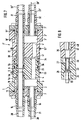
- Fig. 1 shows a longitudinal section through the nut part 1 of a connector for water-cooled, current-carrying lines. It consists of a housing 2 , which is preferably made of plastic, for example polyamide, in which passage openings for the cooling water and bushings for the electrical lines 28 are created through stepped bores and cavities.
- the housing 2 has a pot-shaped chamber 3 that extends approximately to half its depth, from the bottom of which three tubular passages 4 lead through the other (solid) half of the housing 2 at an angular distance of 120 ° (see also FIG. 3 ). Between the two upper passages 4 there is also a continuous bore 5 , which has an equally large gradation 6 , 6a in its interior in both directions, so that two approximately equal sections 5a and 5b of the bore 5 are formed.
- the chamber 3 is covered by a closure piece 7 , which is screwed on a projecting collar 8 against the annular surface 9 of the housing wall 10 .
- the closure piece 7 is sealed against the housing wall 10th
- the closing piece 7 has two continuous round holes 12, 13, one of which 12 with the borehole 5 and the bore portions 5a, 5b is aligned in the housing. 2
- a metal shell 14, 15, preferably made of a copper alloy, is inserted into each of the two openings 12, 13 , which are held therein at gradations 16 , 17 and are sealed by sealing rings 18 , 19 against the wall of the relevant opening 12 , 13 .
- Both metal sleeves 14, 15 protrude with one end from the closure piece 7 to such an extent that hoses 20, 21 for the supply and discharge of cooling water can be pushed onto them and held thereon with clips 22 in a sealing manner.
- the one metal sleeve 15 which forms the connection for the hose 21 supplying the cooling water in the direction of the induction coil, not shown, is flush with the inside of the closure piece 7 , while the other metal sleeve 14 is extended such that it passes through the chamber 3 through protrudes into the section 5a of the aligned bore 5 in the housing 2 and can abut the step 6a there .
- the section 5b of the bore 5 serves, as will become clear further below, for the connection of the line leading the returning cooling water between the male part 1 ' and the female part 1 of the plug connection.
- FIGS. 2 , 5 and 6 Corresponding to the mother part 1 in FIGS. 1 , 3 and 4 , the father part 1 'of the plug connection is shown in FIGS . 2 , 5 and 6 , which is largely constructed in a mirror image in the same way; The same parts are therefore labeled with the same reference numbers, which are deleted to distinguish them.
- the housing 2 'of the male part 1' also has in its one half a pot-shaped chamber 3 ' , from the bottom of which three openings 4' for the cooling water extend through the other half of the housing 2 ' , offset by 120 ° (see also Fig. 5 ), which are arranged so that they are aligned with the passages 4 of the nut part 1 in the assembled state of the plug connection. Between two of the passages 4 'there is a bore 30 which in this case is smooth and which, in the assembled state of the plug connection, is aligned with the outwardly open section 5b of the bore 5 in the nut part 1 .
- closure piece 7 ' Against the housing wall 10 'final annular surface 9' of the housing 2 'a closure piece is in turn 7' screwed and sealed by an O-ring 11 'against the housing wall 10'.
- the closure piece 7 ' also has the two openings 12' , 13 ' , one of which 12' is aligned with the bore 30 .
- In the openings 12 ', 13' sealingly inserted are two metal sleeves 31, 32, on the ends of which protrude from the closure piece 7 ' , hoses 20' and 21 ' for the inflow and outflow of the cooling water are pushed on and held by clips 22' .
- the one shorter metal sleeve 32 in the opening 13 ' closes flush with the closure piece 7' on the inside, so that the passage for the cooling water determined by this metal sleeve 32 opens into the chamber 3 ' .
- the longer metal sleeve 31 in the opening 12 ' protrudes through this chamber 3' and the bore 30 aligned with the opening 12 ' and out of the bore 30 by a certain amount.
- the end of the metal sleeve 31 protruding from the bore 30 is provided with a sealing ring 33 inserted into an annular groove and thus fits sealingly into the section 5b of the bore 5 of the nut part 1 (see also FIG. 7 ).
- the housing 2 ' has a tubular extension 34 projecting beyond the end of the metal sleeve 31 by a small amount, which fits onto the end section 35 of the housing 2 of the nut part 1 facing away from the closure piece 7 , the outer surface of the end section 35 of the housing 2 then countering the inner surface of the tubular extension 34 of the housing 2 ' is sealed by sealing rings 36 .
- a gap 41 of approximately 2 mm remains between the opposing surfaces of the two parts.
- the plug connection is preferably arranged between the power generator and a coaxial transformer of the power supply, and the electric power lines 28, 28 ' , as mentioned, are each guided inside the hoses 21, 21' of the cooling water circuit; they can also be embedded in the wall of the tubes 21, 21 ' . They preferably consist of six wires with a respective cross section of 0.5 mm 2 . At the level of the plug connection or within the chamber 3, 3 ' of the mother part 1 and the father part 1' , these wires are divided into two groups of three wires each, which are then connected to the contact sleeves 23 in the mother part 1 or the contact pins 38 in the father part 1 ' are connected.
- the contact pins 38 make electrical contact with the spring-loaded contact sleeves 23 and, on the other hand, a circuit for the cooling water which is completely sealed off from the outside is closed (see FIG. 7, 8 and 9 ). 7 , the cooling water flows through the hose 21 and the metal sleeve 15 into the chamber 3 of the female part 1 and from there through the passages 4 , the gap 41 and the passages 4 ' into the chamber 3' of the male part 1 ' and on the hose 21 ' in the direction of the tool head or induction coil (not shown).
- the electrical lines 28 , 28 ', and in particular the housing parts in which the electrical contact sleeves 23 and the contact pins 38 are located, are washed by the cooling water and thus continuously cooled.
- the reflux of the heated cooling water from the likewise washed and cooled induction coil then takes place directly through the hose 20 ' , the metal sleeve 31, the bore 5 and the metal sleeve 14 in the nut part and through the hose 20 to the cooling water tank, not shown, without the chambers 3 again . 3 ' and the passages 4 , 4' to pass so that it can not mix with the incoming cooling water and can cool down quickly.
- the connecting sockets and plugs for various supply lines are fixedly mounted, for example, in the carrier plate 42 on the consumer side there are approximately a number of connecting nipples 44, a pin housing 45 and two guide columns 46 and in the supply side Carrier plate 43 there are the corresponding connection sockets 47, a socket housing 48 and two guide sockets 49 .
- a bore 50 is provided in both carrier plates 42 , 43 , into which, as indicated by dash-dotted lines in FIG.
- the male part 1 'on the customer side and the female part 1 of a plug connection according to the invention can be installed on the supply side.
- metal mounting rings 51 , 51 ' are provided on the circumference of the housings 2 and 2' in annular grooves, with the aid of which the parts in the bores 50 of the carrier plates 42 , 43 are held. The result is a compact and reliable multi-plug connection that can be operated easily and quickly by hand when the tool needs to be serviced or a tool replacement is required.
Landscapes
- Connector Housings Or Holding Contact Members (AREA)
- Quick-Acting Or Multi-Walled Pipe Joints (AREA)
- General Induction Heating (AREA)
Description
- Fig. 1
- das Mutterteil der erfindungsgemäßen Schnellkupplung, längs geschnitten,
- Fig. 2
- das Vaterteil der erfindungsgemäßen Schnellkupplung, längs geschnitten,
- Fig. 3
- die Ansicht des Mutterteils der erfindungsgemäßen Schnellkupplung in Richtung des Pfeiles P in Fig. 1,
- Fig. 4
- einen vor bzw. hinter der Schnittebene der Fig. 1 geführten Längsschnitt durch ein Detail des Mutterteils gemäß der Schnittlinie IV - IV in Fig. 3,
- Fig. 5
- die Ansicht des Vaterteils der erfindungsgemäßen Schnellkupplung in Richtung des Pfeiles Q in Fig. 2,
- Fig. 6
- einen vor bzw. hinter der Schnittebene der Fig. 2 geführten Längsschnitt durch eine Detail des Vaterteils gemäß der Schnittlinie VI -VI in Fig. 5,
- Fig. 7
- einen Längsschnitt durch die erfindungsgemäße Schnellkupplung im zusammengefügten Zustand der Teile gemäß Fig. 1 und 2,
- Fig. 8
- einen vor bzw. hinter der Schnittebene der Fig. 7 entsprechend den Fig. 5 und 6 geführten Längsschnitt durch die betreffenden Details im zusammengefügten Zustand der Steckverbindung,
- Fig. 9
- einen Längsschnitt durch die Steckverbindung im zusammengefügten Zustand gemäß der abgeknickten Schnittlinie IX - IX in Fig. 3 bzw. 5 und
- Fig. 10
- die perspektivische Darstellung eines Werkzeugwechselsystems, in dem neben anderen Verbindungen auch eine Steckverbindung nach der Erfindung enthalten ist.
Claims (8)
- Steckverbindung für wassergekühlte, stromführende Leitungen, insbesondere für zweipolige Hochfrequenz-Stromleitungen für Induktionserwärmung an Werkzeugen, mit einer Kammer (3') im Gehäuse (2') eines Vaterteils (1') der Steckverbindung,
dadurch gekennzeichnet,daß im Gehäuse (2) eines Mutterteils (1) der Steckverbindung ebenfalls eine Kammer (3) und in beide Kammern (3, 3') mündende Durchlässe (4, 4') für zufließendes Kühlwasser ausgebildet sind, die im zusammengesteckten Zustand der Steckverbindung miteinander in Verbindung stehen, wobei aus den Kammern (3, 3') jeweils eine direkte Verbindung zu einem das Kühlwasser zuführenden und zur Kühlung weiterführenden Wasserschlauch (21, 21') besteht,daß für den Rückfluß des Kühlwassers eine direkte, die Kammern (3, 3') jeweils überbrückende Verbindung (5) zwischen einem das Kühlwasser dem Vaterteil (1') zuführenden Wasserschlauch (20') und einem das Kühlwasser vom Mutterteil (1) aus weiter führenden Wasserschlauch (20) besteht,daß im Gehäuse (2) des Mutterteils (1) in neben den Durchlässen (4) vorgesehenen Bohrungen (24) zwei Kontakthülsen (23) einer elektrischen bipolaren Steckverbindung befestigt sind und im Gehäuse (2') des Vaterteils (1') in neben den Durchlässen (4') vorgesehenen Bohrungen (37) den Kontakthülsen (23) entsprechende, aus der Stirnfläche des Gehäuses (2') vorstehende Kontaktstifte (38) der elektrischen bipolaren Steckverbindung befestigt sind, unddaß mit den Kontakthülsen (23) und den Kontaktstiften (38) verbundene elektrische Leitungen (28, 28') für die Stromversorgung innerhalb der das Kühlwasser zuführenden und weiterführenden Wasserschläuche (21, 21') geführt sind. - Steckverbindung nach Anspruch 1, dadurch gekennzeichnet, daß die Kammer (3, 3') im Mutterteil (1) und Vaterteil (1') jeweils nach außen durch ein gegen die Gehäusewand (10, 10') abgedichtetes Verschlußstück (7, 7') verschlossen ist, in dem jeweils zwei Öffnungen (12, 13) und (12', 13') vorgesehen sind, in die je zwei Metallhülsen (14, 15) und (31, 32) dichtend eingeschoben sind, von denen die eine, jeweils kürzere (15, 32) in die Kammer (3, 3') mündet und die andere, jeweils längere (14, 31) durch die Kammer (3, 3') hindurch geführt ist und bis in eine mit der betreffenden Öffnung (12, 12') fluchtende Bohrung (5, 30) des an die Kammer (3, 3') anschließenden Gehäuseabschnitts reicht, und daß auf die aus dem Verschlußstück (7, 7') herausragenden Enden der Metallhülsen (14, 15) bzw. (31, 32) Schläuche (20, 21) bzw. (20', 21') für den Zu- und Rückfluß des Kühlwassers aufgeschoben und durch Klammem (22) gehalten sind.
- Steckverbindung nach Anspruch 2, dadurch gekennzeichnet, daß im Mutterteil (1) die längere Metallhülse (14) in den durch eine Abstufung (6a) bestimmten inneren Bohrungsabschnitt (5a) der Bohrung (5) reicht und am Vaterteil (1') die längere Metallhülse (31) aus der glatt durchgehenden Bohrung (30) um ein bestimmtes Maß herausragt und dieses herausragende Ende beim Zusammenfügen der Steckverbindung dichtend in den durch eine Abstufung (6) bestimmten äußeren Bohrungsabschnitt (5b) der Bohrung (5) im Mutterteil (1) paßt und darin gegen die Wand durch einen Dichtring (33) abgedichtet ist.
- Steckverbindung nach Anspruch 3, dadurch gekennzeichnet, daß am Gehäuse (2') des Vaterteils (1') ein über das Ende der aus der Stirnfläche herausragenden Metallhülse (31) und die ebenfalls aus der Stirnfläche herausragenden Kontaktstifte (38) um ein geringes Maß hinausragender, rohrförmiger Fortsatz (34) angeformt ist, der beim Zusammenfügen der Steckverbindung auf den Endabschnitt (35) des Gehäuses (2) des Mutterteils (1) paßt und dagegen durch Dichtringe (36) abgedichtet ist.
- Steckverbindungen nach Anspruch 1, dadurch gekennzeichnet, daß im Gehäuse (2, 2') des Vaterteils (1') und des Mutterteils (1) jeweils drei Durchlässe (4, 4') für das zufließende Kühlwasser vorgesehen sind, die zueinander um 120° versetzt sind, wobei im zusammengefügten Zustand der Steckverbindung die Durchlässe (4) des Mutterteils (1) mit den Durchlässen (4') des Vaterteils (1') fluchten und daß zwischen den Durchlässen (4; 4') ebenfalls um 120° zueinander versetzt jeweils zwei Bohrungen (24; 37) für die elektrischen Kontakthülsen (23) bzw. die elektrischen Kontaktstifte (38) und jeweils eine Bohrung (5;30) für die Anschlüsse des Wasserrücklaufs ausgeführt sind.
- Steckverbindung nach Anspruch 1, dadurch gekennzeichnet, daß die innerhalb der das Kühlwasser zuführenden und weiterleitenden Wasserschläuche (21,21') und der daran anschließenden, kürzeren, sich in die Kammern (3, 3') öffnenden Metallhülsen (15, 32) geführten elektrischen Leitungen (28, 28') jeweils aus sechs Drähten bestehen, die sich in Höhe der Kammern (3, 3') des Mutter- und Vaterteils (1, 1') jeweils in zwei Gruppen zu drei Drähten teilen, die dann mit den Kontakthülsen (23) bzw. den Kontaktstiften (38) fest verbunden sind.
- Steckverbindung nach einem der vorangehenden Ansprüche, dadurch gekennzeichnet, zur Sicherung der Verbindung zwischen Mutterteil (1) und Vaterteil (1') am Umfang ein Schließring mit Bajonett- oder Schraubverschluß vorgesehen ist.
- Steckverbindung nach einem der Ansprüche 1 bis 6, dadurch gekennzeichnet, daß am Umfang des Gehäuses (2, 2') sowohl des Mutterteils (1) als auch des Vaterteils (1') in einer Ringnut jeweils ein Montagering (51, 51') eingepaßt ist, mit dessen Hilfe das Mutterteil (1) und das Vaterteil (1') an jeweils einer Trägerplatte (42, 43) fest montierbar sind.
Applications Claiming Priority (3)
| Application Number | Priority Date | Filing Date | Title |
|---|---|---|---|
| DE19916984 | 1999-04-15 | ||
| DE19916984A DE19916984C1 (de) | 1999-04-15 | 1999-04-15 | Steckverbindung für wassergekühlte, stromführende Leitungen an Werkzeugen und anderen Geräten |
| PCT/EP2000/002649 WO2000064011A1 (de) | 1999-04-15 | 2000-03-25 | Steckverbindung für wassergekühlte, stromführende leitungen an werkzeugen |
Publications (2)
| Publication Number | Publication Date |
|---|---|
| EP1173903A1 EP1173903A1 (de) | 2002-01-23 |
| EP1173903B1 true EP1173903B1 (de) | 2003-08-13 |
Family
ID=7904633
Family Applications (1)
| Application Number | Title | Priority Date | Filing Date |
|---|---|---|---|
| EP00922547A Expired - Lifetime EP1173903B1 (de) | 1999-04-15 | 2000-03-25 | Steckverbindung für wassergekühlte, stromführende leitungen an werkzeugen |
Country Status (8)
| Country | Link |
|---|---|
| US (1) | US6471530B1 (de) |
| EP (1) | EP1173903B1 (de) |
| JP (1) | JP3683815B2 (de) |
| KR (1) | KR20010103706A (de) |
| CZ (1) | CZ20012026A3 (de) |
| DE (1) | DE19916984C1 (de) |
| ES (1) | ES2204563T3 (de) |
| WO (1) | WO2000064011A1 (de) |
Families Citing this family (25)
| Publication number | Priority date | Publication date | Assignee | Title |
|---|---|---|---|---|
| DE10212413B4 (de) * | 2002-03-21 | 2016-02-25 | Valeo Auto-Electric Wischer Und Motoren Gmbh | Waschwasserschlauch und Steckverbinder |
| DE102005037864B4 (de) * | 2005-08-10 | 2008-11-27 | Schaltbau Gmbh | Ladesteckverbinder |
| FR2915788B1 (fr) | 2007-05-04 | 2012-05-25 | Airbus France | Dispositif de connexion multi-systemes a bord d'un aeronef |
| US8028533B2 (en) * | 2007-11-28 | 2011-10-04 | E & J Enterprises, Llc | Defrost indicator |
| US8288986B2 (en) | 2008-04-28 | 2012-10-16 | Aerovironment Inc. | Concentric connector for electric vehicles |
| US8305760B2 (en) | 2008-05-16 | 2012-11-06 | Parker-Hannifin Corporation | Modular high-power drive stack cooled with vaporizable dielectric fluid |
| US8035475B2 (en) * | 2008-08-14 | 2011-10-11 | Kanthal Corporation | Quick connect fittings |
| DE102009042569B3 (de) * | 2009-09-23 | 2011-05-05 | SCHLÖGL, Hilde | Steckkupplung |
| DE102009042568B4 (de) * | 2009-09-23 | 2012-03-01 | Hilde Schlögl | Steckkupplungssystem |
| DE202010006813U1 (de) | 2010-05-14 | 2010-09-09 | Huber + Suhner Ag | Koaxialer Hochfrequenzverbinder |
| WO2012051510A2 (en) * | 2010-10-14 | 2012-04-19 | Gregory Thomas Mark | Actively cooled electrical connection |
| US8998651B2 (en) * | 2013-07-10 | 2015-04-07 | Bellwether Electronic Corp. | Plug having a body with a plurality of bars in a first direction and a second direction each with a channel to accommodate a terminal |
| EP3473309A1 (de) * | 2015-01-09 | 2019-04-24 | Ironburg Inventions | Controller für eine spielekonsole |
| CN109076717A (zh) * | 2016-02-18 | 2018-12-21 | 法拉第未来公司 | 使用液体冷却的充电连接器 |
| DE102016105347A1 (de) * | 2016-03-22 | 2017-09-28 | Phoenix Contact E-Mobility Gmbh | Steckverbinderteil mit einem gekühlten Kontaktelement |
| DE102016105311A1 (de) * | 2016-03-22 | 2017-09-28 | Phoenix Contact E-Mobility Gmbh | Steckverbinderteil mit einem gekühlten Kontaktelement |
| DE102016112306A1 (de) * | 2016-07-05 | 2018-01-11 | HARTING Automotive GmbH | Flüssigkeitsgekühltes Kontaktelement |
| SE540885C2 (en) * | 2016-11-07 | 2018-12-11 | Cejn Ab | Junction box, connector, and a method for ejecting the connector |
| DE102016225527A1 (de) * | 2016-12-20 | 2018-06-21 | Bayerische Motoren Werke Aktiengesellschaft | Verbindungselement und Verbindungsvorrichtung zum elektrischen Verbinden eines Kabels mit einem elektrischen Gerät eines Kraftfahrzeugs |
| DE102017212495A1 (de) * | 2017-07-20 | 2019-01-24 | Siemens Aktiengesellschaft | Elektrischer Steckverbinder, Anordnung mit einem elektrischen Steckverbinder, Verwendung eines elektrischen Steckverbinders und Verfahren zum Betrieb eines elektrischen Steckverbinders |
| US10756498B1 (en) * | 2019-03-22 | 2020-08-25 | Te Connectivity Corporation | Terminal heat exchanger for an electrical connector |
| DE102019111749B4 (de) | 2019-05-07 | 2025-06-12 | Te Connectivity Germany Gmbh | Elektrische Steckverbindung sowie elektrische Entität |
| CN112310686B (zh) * | 2019-07-26 | 2025-05-30 | 江苏昆仑光源材料有限公司 | 一种层状镍铁合金带材连续真光亮热复合高频柔性水冷电缆 |
| CN112003094A (zh) * | 2020-08-25 | 2020-11-27 | 陈俊俊 | 一种延时通电的电源连接插座 |
| DE102024101161A1 (de) * | 2024-01-16 | 2025-07-17 | Sms Group Gmbh | Schnellkupplungsvorrichtung, Induktionsheizvorrichtung, Produktionslinie und Verfahren zur Wartung einer derartigen Induktionsheizvorrichtung |
Family Cites Families (7)
| Publication number | Priority date | Publication date | Assignee | Title |
|---|---|---|---|---|
| US4223969A (en) * | 1979-04-20 | 1980-09-23 | Codman & Shurtleff, Inc. | Quick connect-disconnect electrofluidic junction assembly |
| CH672898A5 (de) * | 1987-05-11 | 1990-01-15 | Praezisions Werkzeuge Ag | |
| DE3912236A1 (de) * | 1989-04-14 | 1990-10-18 | Zeiss Carl Fa | Elektrische steckverbindung |
| DE3936928A1 (de) * | 1989-11-06 | 1991-05-08 | Martin Umwelt & Energietech | Elektropneumatischer steckverbinder |
| US5197895A (en) * | 1991-05-10 | 1993-03-30 | Bicore Monitoring Systems | Disposable electro-fluidic connector with data storage |
| US5229543A (en) * | 1991-10-28 | 1993-07-20 | Electro-Max Mfg. Co. | Fluid cooled power conductor and method of making the same |
| DE19638521C2 (de) * | 1996-09-20 | 1998-07-30 | Raymond A & Cie | Vorrichtung zum automatisierten Setzen von Haltebolzen auf Trägerflächen |
-
1999
- 1999-04-15 DE DE19916984A patent/DE19916984C1/de not_active Expired - Fee Related
-
2000
- 2000-03-25 ES ES00922547T patent/ES2204563T3/es not_active Expired - Lifetime
- 2000-03-25 WO PCT/EP2000/002649 patent/WO2000064011A1/de not_active Ceased
- 2000-03-25 EP EP00922547A patent/EP1173903B1/de not_active Expired - Lifetime
- 2000-03-25 JP JP2000613041A patent/JP3683815B2/ja not_active Expired - Fee Related
- 2000-03-25 CZ CZ20012026A patent/CZ20012026A3/cs unknown
- 2000-03-25 KR KR1020017006671A patent/KR20010103706A/ko not_active Withdrawn
- 2000-03-25 US US09/958,234 patent/US6471530B1/en not_active Expired - Fee Related
Also Published As
| Publication number | Publication date |
|---|---|
| DE19916984C1 (de) | 2000-07-13 |
| JP2002542595A (ja) | 2002-12-10 |
| WO2000064011A1 (de) | 2000-10-26 |
| JP3683815B2 (ja) | 2005-08-17 |
| CZ20012026A3 (cs) | 2002-01-16 |
| EP1173903A1 (de) | 2002-01-23 |
| ES2204563T3 (es) | 2004-05-01 |
| KR20010103706A (ko) | 2001-11-23 |
| US6471530B1 (en) | 2002-10-29 |
Similar Documents
| Publication | Publication Date | Title |
|---|---|---|
| DE19916984C1 (de) | Steckverbindung für wassergekühlte, stromführende Leitungen an Werkzeugen und anderen Geräten | |
| EP3512736B1 (de) | Steckverbinderteil mit gekühlten kontaktelementen zum laden von elektrischen fahrzeugen | |
| DE69315631T2 (de) | Bahnschweissvorrichtung mit Sicherheitsverriegelung | |
| AT508285B1 (de) | Anschlusssystem mit einer kupplungsvorrichtung und einem steckelement für einen schweissbrenner | |
| DE3202465A1 (de) | Plasmabrenner | |
| DE69132150T2 (de) | Befestigungsvorrichtung | |
| EP2104183A1 (de) | Elektrische Verbindungseinrichtung und Verbinder | |
| AT508286A2 (de) | Brennerwechselmodul, schweissbrenner, rohrbogen, brennerhalterung, schlauchpaket für einen schweissbrenner, aufnahmemodul, brennerwechselsystem und verfahren zum automatischen wechseln eines rohrbogens oder einer brennerhalterung eines schweissbrenners | |
| DD201567A5 (de) | Haltevorrichtung | |
| EP1050200A1 (de) | Brenner für schneidverfahren | |
| EP2673103B1 (de) | SCHWEIßGERÄT | |
| EP1023156B1 (de) | Vorrichtung zum anschweissen einer armatur an ein rohr mittels in der armatur integrierter elektrischer heizelemente | |
| EP3691822A1 (de) | Schweissstromquelle | |
| DE19904651A1 (de) | Vorrichtung zur Befestigung eines Elektrodenarms an einer Schweißzange | |
| EP3485559B1 (de) | Wasserkammerdeckel für wasserkühlsystem einer elektrischen maschine | |
| DE102019126651A1 (de) | Lichtbogenbrenner und Lichtbogen-Drahtspritzeinrichtung | |
| DE9401605U1 (de) | Steckverbindung | |
| EP1126177B1 (de) | Elektrisch-Hydraulische Schnittstelle | |
| AT512822B1 (de) | Steckelement für einen Schweißbrenner | |
| EP0046999B1 (de) | Elektrische Schweisspistole mit drehbarem Brennerkopf | |
| DE10034421B4 (de) | Induktor | |
| AT512824B1 (de) | Kupplung für ein Schlauchpaket eines Schweißbrenners | |
| EP1692922A1 (de) | Plasmaspritzvorrichtung | |
| AT512825B1 (de) | Stromkupplung für einen Schweißbrenner | |
| EP1726863A1 (de) | Vorrichtung zum Einrichten eines Übergangs zwischen einer metallischen Armatur und einem Kunststoffrohr |
Legal Events
| Date | Code | Title | Description |
|---|---|---|---|
| PUAI | Public reference made under article 153(3) epc to a published international application that has entered the european phase |
Free format text: ORIGINAL CODE: 0009012 |
|
| 17P | Request for examination filed |
Effective date: 20011115 |
|
| AK | Designated contracting states |
Kind code of ref document: A1 Designated state(s): AT BE CH CY DE DK ES FI FR GB GR IE IT LI LU MC NL PT SE |
|
| GRAH | Despatch of communication of intention to grant a patent |
Free format text: ORIGINAL CODE: EPIDOS IGRA |
|
| GRAH | Despatch of communication of intention to grant a patent |
Free format text: ORIGINAL CODE: EPIDOS IGRA |
|
| GRAA | (expected) grant |
Free format text: ORIGINAL CODE: 0009210 |
|
| AK | Designated contracting states |
Designated state(s): BE ES FR GB IT |
|
| PG25 | Lapsed in a contracting state [announced via postgrant information from national office to epo] |
Ref country code: FR Free format text: LAPSE BECAUSE OF NON-PAYMENT OF DUE FEES Effective date: 20030813 |
|
| REG | Reference to a national code |
Ref country code: GB Ref legal event code: FG4D Free format text: NOT ENGLISH |
|
| REG | Reference to a national code |
Ref country code: IE Ref legal event code: FG4D Free format text: GERMAN |
|
| GBT | Gb: translation of ep patent filed (gb section 77(6)(a)/1977) |
Effective date: 20031025 |
|
| REG | Reference to a national code |
Ref country code: IE Ref legal event code: FD4D |
|
| REG | Reference to a national code |
Ref country code: ES Ref legal event code: FG2A Ref document number: 2204563 Country of ref document: ES Kind code of ref document: T3 |
|
| PLBE | No opposition filed within time limit |
Free format text: ORIGINAL CODE: 0009261 |
|
| STAA | Information on the status of an ep patent application or granted ep patent |
Free format text: STATUS: NO OPPOSITION FILED WITHIN TIME LIMIT |
|
| 26N | No opposition filed |
Effective date: 20040514 |
|
| EN | Fr: translation not filed | ||
| PGFP | Annual fee paid to national office [announced via postgrant information from national office to epo] |
Ref country code: BE Payment date: 20050323 Year of fee payment: 6 |
|
| PG25 | Lapsed in a contracting state [announced via postgrant information from national office to epo] |
Ref country code: BE Free format text: LAPSE BECAUSE OF NON-PAYMENT OF DUE FEES Effective date: 20060331 |
|
| BERE | Be: lapsed |
Owner name: A. *RAYMOND & CIE Effective date: 20060331 |
|
| PGFP | Annual fee paid to national office [announced via postgrant information from national office to epo] |
Ref country code: ES Payment date: 20090227 Year of fee payment: 10 |
|
| PGFP | Annual fee paid to national office [announced via postgrant information from national office to epo] |
Ref country code: GB Payment date: 20090317 Year of fee payment: 10 |
|
| PGFP | Annual fee paid to national office [announced via postgrant information from national office to epo] |
Ref country code: IT Payment date: 20090320 Year of fee payment: 10 |
|
| GBPC | Gb: european patent ceased through non-payment of renewal fee |
Effective date: 20100325 |
|
| PG25 | Lapsed in a contracting state [announced via postgrant information from national office to epo] |
Ref country code: GB Free format text: LAPSE BECAUSE OF NON-PAYMENT OF DUE FEES Effective date: 20100325 Ref country code: IT Free format text: LAPSE BECAUSE OF NON-PAYMENT OF DUE FEES Effective date: 20100325 |
|
| REG | Reference to a national code |
Ref country code: ES Ref legal event code: FD2A Effective date: 20110415 |
|
| PG25 | Lapsed in a contracting state [announced via postgrant information from national office to epo] |
Ref country code: ES Free format text: LAPSE BECAUSE OF NON-PAYMENT OF DUE FEES Effective date: 20110404 |
|
| PG25 | Lapsed in a contracting state [announced via postgrant information from national office to epo] |
Ref country code: ES Free format text: LAPSE BECAUSE OF NON-PAYMENT OF DUE FEES Effective date: 20100326 |