EP1173644B1 - Système structurel d'éléments de torsion/toroidaux - Google Patents
Système structurel d'éléments de torsion/toroidaux Download PDFInfo
- Publication number
- EP1173644B1 EP1173644B1 EP00918149A EP00918149A EP1173644B1 EP 1173644 B1 EP1173644 B1 EP 1173644B1 EP 00918149 A EP00918149 A EP 00918149A EP 00918149 A EP00918149 A EP 00918149A EP 1173644 B1 EP1173644 B1 EP 1173644B1
- Authority
- EP
- European Patent Office
- Prior art keywords
- torsion
- toroidal
- elements
- structural
- structural elements
- Prior art date
- Legal status (The legal status is an assumption and is not a legal conclusion. Google has not performed a legal analysis and makes no representation as to the accuracy of the status listed.)
- Expired - Lifetime
Links
Images


Classifications
-
- E—FIXED CONSTRUCTIONS
- E04—BUILDING
- E04B—GENERAL BUILDING CONSTRUCTIONS; WALLS, e.g. PARTITIONS; ROOFS; FLOORS; CEILINGS; INSULATION OR OTHER PROTECTION OF BUILDINGS
- E04B1/00—Constructions in general; Structures which are not restricted either to walls, e.g. partitions, or floors or ceilings or roofs
- E04B1/35—Extraordinary methods of construction, e.g. lift-slab, jack-block
-
- E—FIXED CONSTRUCTIONS
- E04—BUILDING
- E04B—GENERAL BUILDING CONSTRUCTIONS; WALLS, e.g. PARTITIONS; ROOFS; FLOORS; CEILINGS; INSULATION OR OTHER PROTECTION OF BUILDINGS
- E04B1/00—Constructions in general; Structures which are not restricted either to walls, e.g. partitions, or floors or ceilings or roofs
- E04B1/32—Arched structures; Vaulted structures; Folded structures
-
- E—FIXED CONSTRUCTIONS
- E04—BUILDING
- E04B—GENERAL BUILDING CONSTRUCTIONS; WALLS, e.g. PARTITIONS; ROOFS; FLOORS; CEILINGS; INSULATION OR OTHER PROTECTION OF BUILDINGS
- E04B1/00—Constructions in general; Structures which are not restricted either to walls, e.g. partitions, or floors or ceilings or roofs
- E04B1/34—Extraordinary structures, e.g. with suspended or cantilever parts supported by masts or tower-like structures enclosing elevators or stairs; Features relating to the elastic stability
-
- E—FIXED CONSTRUCTIONS
- E04—BUILDING
- E04B—GENERAL BUILDING CONSTRUCTIONS; WALLS, e.g. PARTITIONS; ROOFS; FLOORS; CEILINGS; INSULATION OR OTHER PROTECTION OF BUILDINGS
- E04B1/00—Constructions in general; Structures which are not restricted either to walls, e.g. partitions, or floors or ceilings or roofs
- E04B1/32—Arched structures; Vaulted structures; Folded structures
- E04B2001/3235—Arched structures; Vaulted structures; Folded structures having a grid frame
- E04B2001/3241—Frame connection details
-
- E—FIXED CONSTRUCTIONS
- E04—BUILDING
- E04B—GENERAL BUILDING CONSTRUCTIONS; WALLS, e.g. PARTITIONS; ROOFS; FLOORS; CEILINGS; INSULATION OR OTHER PROTECTION OF BUILDINGS
- E04B1/00—Constructions in general; Structures which are not restricted either to walls, e.g. partitions, or floors or ceilings or roofs
- E04B1/32—Arched structures; Vaulted structures; Folded structures
- E04B2001/327—Arched structures; Vaulted structures; Folded structures comprised of a number of panels or blocs connected together forming a self-supporting structure
- E04B2001/3276—Panel connection details
-
- E—FIXED CONSTRUCTIONS
- E04—BUILDING
- E04B—GENERAL BUILDING CONSTRUCTIONS; WALLS, e.g. PARTITIONS; ROOFS; FLOORS; CEILINGS; INSULATION OR OTHER PROTECTION OF BUILDINGS
- E04B1/00—Constructions in general; Structures which are not restricted either to walls, e.g. partitions, or floors or ceilings or roofs
- E04B1/32—Arched structures; Vaulted structures; Folded structures
- E04B2001/327—Arched structures; Vaulted structures; Folded structures comprised of a number of panels or blocs connected together forming a self-supporting structure
- E04B2001/3288—Panel frame details, e.g. flanges of steel sheet panels
Definitions
- the patent classification system does not contain a classification for structural systems as such, the most appropriate description of the present invention, but does address specific types of structures, such as "static structures" (U. S. Class 52), "bridges” (U. S. Class 14),"railway rolling stock” (U. S. Class/Subclass 105/396+),”ships" (U. S. Class/Subclass 114/65+), “aeronautics” (U. S. Class/Subclass 244/117+),”land vehicles: bodies and tops” (U. S. Class 296) etc.
- torsion devices no structural classification could be found, the classifications being restricted to springs (U. S. Class 267), etc.
- the present invention has elements that may be considered to be covered generally by U. S Class/Subclass 152/1-13, spring wheels and resilient tires and wheels, and U. S. Class/Subclass 152/516-520,”run-flat" devices.
- the present invention is a structural system as claimed in claim 1.
- torsion element means a structural element that functions with torsion as its principal load bearing mode.
- the term "toroidal” means of or pertaining to a "toroid".
- the term “toroid” is not intended to limit the present invention to employment of elements that are in the shape of a torus, which is mathematically defined as a surface, and the solid of rotation thereby bounded, obtained by rotating a circle which defines the cross section of the tube of the torus about an axis in the plane of the circular cross section.
- the term "toroid” means any form with the general features of a torus, i. e.
- a toroid may be formed by the connection of cylindrical or prismatic sections, straight or curved, or by the connection of straight and curved sections in any combination or order; and may be of any shape which the closed tube may form: elliptical, circular, polygonal, whether regular or irregular, symmetrical, partially symmetrical, or even asymmetrical, whether convex or concave outward, partially or completely.
- the term "toroid” applies to and includes: (a) the continuous surfaces of toroids, tube walls of finite thickness, the exterior of which are bounded by the toroidal surface, and the solids that are bounded by the toroidal surface; (b) any framework of elements which if sheathed would have the shape of a toroid; (c) any framework of elements which lays in the locus of a toroidal surface; (d) a bundle or coil of fibers, wires, threads, cables, or hollow tubing that are, bound, wound, woven, twisted, glued, welded, or otherwise bonded together in such a manner as to form in their plurality or individuality a toroidal shape.
- a toroidal structural element has no non-toroidal conventional cross-bracing, diametrical or choral, within the interior perimeter of its tube that functions by compression, tension or other loading.
- a toroidal element may be reinforced within the interior perimeter of its tube by other toroidal elements, as shown in FIGS. 78-81 , which may be torsional, conventional or otherwise.
- torsion/toroidal element means a structural element that may be either a torsion element, or a toroidal element, or a toroidal torsion element, the term “torsion/toroidal element” thus encompassing all three alternatives. Otherwise, when any one of the foregoing alternative meanings are referred to, that alternative shall be specifically referred to by its proper description: torsion element; toroidal element; or toroidal torsion element. However, reference to a torsion element shall be taken to mean a torsion element which may be toroidal or non-toroidal; and reference to a toroidal element shall mean a toroidal element which may be torsional or non-torsional.
- the structural system is comprised of a plurality of torsion/toroidal elements connected together so that there is no substantial unwanted movement of the torsion/toroidal elements in relation to one another in the connection. Two or more torsion/toroidal elements may be connected in the same connection.
- the connection of the torsion/toroidal elements is the means by which loading is transmitted between and distributed among the torsion/toroidal elements.
- connection means, in addition to its ordinary meaning, being in a “connection” with torsion/toroidal elements; and the term “connection” as used in this disclosure includes, in addition to its ordinary meaning, any combination of components and processes that results in two or more structural elements being connected, and further includes the space actually occupied by such components, the objects resulting from such processes, and the parts of the structural elements connected by contact with such components or objects; but both the terms “connected” and “connection” exclude interlinking ("intersection") of structural elements as a means for connecting toroidal elements.
- the structural system of connected torsion elements may be utilized for constructions without the employment of toroidal elements, and the structural system of connected toroidal elements may be utilized for constructions without the employment of torsion elements, the preferred embodiment and the best mode is in combination with the other, a structural system of connected toroidal torsion elements.
- the structural system of torsion elements and the structural system of toroidal elements are each operative separately (without combination with the other), they are joined in the inventive concept of the structural system of toroidal torsion elements by the complementary characteristics of the toroidal shape with torsion load bearing.
- Torsion/toroidal elements use the strength of materials more effectively and have the capacity to redistribute the loads distributed to them by the connections of the structural system of which they are a part.
- the structural system effectively distributes most compression, tension, flexion and torsion loading among the connected torsion/toroidal elements of constructions.
- the construction is distinguished from conventional constructions employing elements which function only in compression, tension or flexion, such as beams, struts, joists, decks, trusses, etc.
- elements which function in compression, tension or flexion are constructed using the present invention, the same structural benefit of load distribution applies.
- An embodiment of the present invention employs toroidal elements that are constructed with the use of torsion elements which are toroidal in shape.
- Torsion elements use the torsional strength of materials and have the capacity to bear the torsion loads distributed to them by the connections of the structural system of which they are a part.
- the preferred embodiment using toroidal torsion elements converts most compression, tension and flexion loading of constructions using the system to torsional loading of the torsion elements of which the constructions are comprised.
- the use of toroidal torsion elements also contributes to construction of toroids which are self-supporting.
- torsion/toroidal elements may be constructed of yet other torsion/toroidal elements, so that a given torsion/toroidal element so constructed functions to bear loads by the bearing of structural loads by its constituent substructures.
- Such substructures may be structural elements, torsion/toroidal, conventional or otherwise, which are part of a combination of structural elements of a scale similar to the given toroidal element, or structural elements of a scale significantly smaller than the given torsion/toroidal element and fundamentally underlying the bearing capacity of the given torsion/toroidal element.
- the structure of a given torsion/toroidal element may be the replication of small substructures of torsion/toroidal elements, which in turn may be replications of still smaller substructures of torsion/toroidal elements.
- This process of structural replication can be continued to microscopic, and even molecular, levels of smallness.
- the system also includes the construction of conventional elements using torsion/toroidal elements which may be used in combination with other torsion/toroidal structures in constructions.
- conventional elements such as beams, joists, decks, trusses, etc., constructed using torsion/toroidal elements may be engineered with arching camber and prestressing.
- torsion/toroidal elements which may be bearing torsion loads, and is not fundamentally (in the sense of originally underlying) or necessarily dependent on elements such as linear chords and struts bearing loads in compression, tension or flexion.
- Torsion/toroidal elements can be made of virtually any material suitable for the loads to which the structure may be subjected and for the environment in which the structure may be utilized.
- torsion elements bear as torsional load the greatest part of the load placed on the structures of which they are a part, excepting localized forces existing in the connection of the torsion elements, and evenly distribute such loading among the connected torsion elements of which the structures are ultimately and fundamentally constructed.
- the present invention contemplates that structures constructed of connected torsion/toroidal elements may be incorporated in yet other structures together with conventional structural elements in order to bear compression, tension and flexion loads with such torsion/toroidal structures.
- Torsion elements may have virtually any shape that allows them to be connected and thereby function by torsional loading.
- the preferred embodiment of the present invention employs torsion elements which are toroidal in shape.
- Such toroidal torsion elements may be used to create a variety of new structural forms for both stationary and moveable structures.
- the toroidal shape facilitates replication of structured toroidal torsion elements to produce larger and larger toroidal torsion elements which may be suitable for the dimension of the ultimate structural application.
- a large variety of structures made feasible by origination of the replication process with torsion/toroidal elements on the order of nanostructures or larger may themselves be considered as materials which can be utilized in conventional structures, such as decking, plates, skins, and sheeting of arbitrary curvature.
- Torsion/toroidal elements may be used to create new structural forms for both stationary and moveable structures.
- the toroidal shape allows for replication of toroidal elements to produce larger and larger toroidal elements which may be suitable to the dimensions of the structural application.
- a large variety of structures made feasible by origination of the replication process with toroidal elements on the order of nanostructures or larger may themselves be considered as materials which can be utilized in conventional structures such as decking, plates, skins, and sheeting of arbitrary curvature.
- Erection of structural frames using the present invention requires only connection of the torsion/toroidal elements, and may use connectors which are prepositioned and even integrated in the design of the torsion/toroidal elements.
- Torsion/toroidal elements may be connected by any means that does not permit unwanted movement in the connection.
- Coupled means may be any type of joining, such as welding, gluing, fusing, or with the use of fasteners, such as pins, screws and clamps.
- the preferred means for connection is by use of a "coupling".
- the term "coupling” is used in this disclosure to mean a device which connects two or more torsion elements by holding them in a desired position relative to one another, so that when the desired positions of the torsion/toroidal elements are achieved, the torsion/toroidal elements will not be able to unwantedly move relative to each other within the coupling.
- the coupling may itself be constructed of torsion/toroidal elements, or may be solid or have some other structure.
- the term "coupling” also includes a device which connects a torsion/toroidal element to a conventional structural element by holding both the torsion/toroidal element and the conventional structural element in the desired position, so that the structural elements will not be able to unwantedly move relative to each other within the coupling.
- the function of couplings is to hold torsion/toroidal elements in position in relation to each other, there may be motion of the torsion/toroidal elements outside the connection associated with the structural loading of the elements, including rotation of the elements with respect to each other about the axis defined by the grip within the coupling, and sliding of the elements through the grip of the coupling. Such motion is expected and appropriate for the distribution of stress among the elements of a given torsion/toroidal structure.
- the function of couplings in holding structural elements in position may be combined with prior positional adjustment and actuation of such adjustment.
- the position of torsion/toroidal elements connected by a coupling with respect to one another may be changed or adjusted and then held in the desired position.
- the coupling must be designed to have the capability for and even to perform such adjustment, and may also be designed to have such adjustment actuated by some motive power.
- Such actuation may implement dynamic distribution of loading among the structural elements affected or implement dynamic shape shifting, or both. This can be achieved by making one or more connections of the structure adjustable, with or without the use of actuation.
- such powered actuation of adjustable coupled connections may be computer controlled in order to precisely determine the shape changes and structural effects desired.
- the function of such a coupling is to adjust the coupled connections, with or without the use of such controlled actuation, so that a torsion/toroidal element may be moved within a connection in relation to other structural elements connected therein, and then firmly held by the connection in the position resulting from such movement so that the torsion/toroidal element will not have substantial movement within the connection in relation to any other structural element in the connection unless deliberately moved again by the coupling.
- FIGS. 1-4 show an alternative to the embodiment of the invention claimed which demonstrates the fundamental principles of the torsional aspect of the structural system.
- two torsion elements 3,4 are connected by two couplings 1,6 to form a torsional structural module.
- the torsion elements 3 and 4 are shown as open rectangles with a circular cross section to demonstrate the principle, but any cross sectional shape and any element shape may be used with couplings having compatible openings.
- the couplings shown 1,6 have cylindrical openings, coupling 6 having bearings 7 which allow for free rotational movement of the torsion elements within the coupling, and coupling 1 having spline grips 2 to engage the spline ends 5 of the torsion elements 3,4.
- the purpose of the spline ends 5 being engaged by corresponding spline grips 2 is to hold the torsion element firmly in relation to the coupling 1 so as to prevent movement of the torsion element within the coupling.
- the purpose of the couplings 6 with bearings is to constrain the arms of the torsion elements 3 and 4 to be in alignment under the action of the forces.
- FIGS. 5-8 By way of additional technical information an alternative to the embodiments of the invention claimed is shown in FIGS. 5-8 .
- the orientation of the torsion elements is opposing, but with the transmission of torque loading accomplished with couplings 21, 26 similar to those in FIGS. 1-4 through the addition of an intermediate torsion element 28, in this case a cylindrical bar.
- an intermediate torsion element 28 in this case a cylindrical bar.
- the purpose of the splines 25 is to engage the spline grips 22 of the couplings 21, thus fixing their rotation with that of the torsion elements 23,24
- the purpose of the couplings 26 with bearings 27 is to constrain the movement of the arms of the torsion elements 23,24 and the intermediate torsion element 28 to rotation in alignment with each other.
- the intermediate torsion element 28 is acted upon with opposing torque by connection at its opposite ends with couplings 21 that transmit the load on the torsion elements 23 and 24.
- the transmission of load to the intermediate torsion element 28 occurs in the same manner as the transmission of load between the torsion elements 3 and 4 of the module shown in FIGS. 1-4 . Therefore, the load transmitted to the intermediate torsion element 28 by one torsion element 23 is opposite to the torsional load transmitted from the other torsion element 24. In this way the intermediate element 28 provides for additional capacity for bearing of torsional loading by the structural module.
- FIGS. 5-8 Although a means for connection between torsion elements 23 and 24 via a single intermediate torsion element 28 is shown in FIGS. 5-8 , the connection between torsion elements 23 and 24 as shown in FIGS. 5-8 may be accomplished using more than one intermediate torsion element and the appropriate combination and placement of couplings.
- FIGS. 1-4 and FIGS. 5-8 are not the only means contemplated for achieving fixed connections between torsion elements and couplings. Indeed all means for fixing a coupling to a torsion element, such as welding, gluing, fusing, pinning, screwing, clamping, and the mating of the coupling with a torsion element of any non-circular cross section, are contemplated as appropriate in order for a coupling connecting torsion elements to transmit torsional loading.
- modules shown in FIGS. 1-4 and 5-8 may themselves be similarly connected in linear arrays and different types of modules shown may be connected to form arrays which may have any shape, and may be closed, circular, or asymmetrical and irregular.
- the torsion elements may be of virtually any shape so long as they may be connected in a way similar to that as shown in FIGS. 1-4 and 5-8 , thus providing for the bearing and transmission of torsional loading.
- An example of another torsion element shape alternative to the claimed embodiments is shown in FIGS. 9 and 10 , connected in the various ways shown in FIGS. 5-8 , again only for the purpose of providing technical information in addition to the embodiments claimed.
- Torsion elements shown in FIGS. 1-8 which have been previously discussed for the purpose of additional technical information, may be angularly connected to produce angular torsion modules and structures and form linear arrays thereof as shown in the example of FIG. 13 .
- the same characteristics of transmission of torsional loading exist in this type of configuration as in the structures shown and discussed earlier.
- Angular connections are possible for virtually any type of torsion element as shown in the examples of FIGS. 11 and 12 .
- any type of connection may be used for angular connection of torsion elements.
- Such angularly connected torsion elements as shown for purposed of additional technical information in FIGS. 11-13 may also be connected in closed arrays as shown in FIG. 14 .
- the angular connection between elements allows for the inclusion of more torsion elements in the array within the same length, thereby providing for a greater capacity of the array to absorb torsional stress.
- any closed array is possible and will share the same characteristics of distribution of torsional loads as circular arrays.
- the symmetry of an array and the manner in which it is loaded will determine the evenness of the distribution of torsional stress, whether the array is open or closed.
- a closed symmetrical array of torsion elements forms a toroid, the shape of the preferred embodiments of the invention.
- modules of torsion elements, and arrays thereof, connected by one coupling are also possible, as shown in FIGS. 15-18 where the torsion elements are toroidal.
- Smoothly curved torsion elements absorb torsion stress variably along the length of the toroidal tube. Torque applied to any point on such a torsion element along its tube length which tends to twist the body of the torsion element is transmitted along the body of the torsion element as determined by the structure of the torsion element, the capacity of the material used to absorb torsional stress, and the curvature of the torsion element. Nevertheless, the load on one curved torsion element fixedly connected with one coupling to another curved torsion element as shown in FIGS. 15-18 will be transmitted to the other in the same manner as for the connected torsion elements shown in FIGS. 1-4 .
- toroidal torsional elements can be connected in closed arrays as shown in FIG. 19 , which may form the framework of larger toroidal elements having torsional strength characteristics. Indeed, it is contemplated by this invention that the self-similarity of toroidal torsion elements constructed from smaller toroidal torsion elements can be extended to precisely control all of the structural characteristics of such toroidal torsion elements.
- FIG. 19 all of the connections between torsion/toroidal elements have been shown in the figures as “external”, i. e. achieved with an “external” coupling applied to the exterior surfaces of torsion/toroidal elements. Such connections shall be continued to be referred to as “external”, as opposed to “internal” connections, which include all means for connecting torsion/toroidal elements without the use of a coupling or other intermediate device.
- Torsion/toroidal elements in an internally connected combination of torsion elements is shown in the various views in FIGS. 20-23 .
- FIGS. 24 and 25 are comprised of toroidal torsion elements that are internally connected.
- observation of an internal connection shown in the various views of FIGS. 26-33 between two toroids formed as shown in FIGS. 24 and 25 , demonstrates that internal connections between toroidal elements may be achieved by the use of external connections between their constituent toroidal elements.
- This internal connection rather than being accomplished by coupling of the constituent toroidal elements of the toroids, could have been accomplished by internal connections between the torsion elements of which the constituent toroidal elements are constructed.
- Such internal connection may also be mediated by additional elements, torsional or otherwise.
- this process may be continually replicated in a self-similar manner on a smaller and smaller scale, down to a fundamental torsion/toroidal element, which may be a construction itself, but not necessarily by formation from a circular array.
- Arrays of angularly connected torsion/toroidal elements that themselves form toroids may be elliptical, as shown in FIGS. 35 and 36 , or of any other shape, and have various directional characteristics, such as where lateral flexion of the resulting torsion/toroidal element is converted to torsional loading of its constituent toroidal torsion elements.
- Such varying constructions of torsion/toroidal elements may be combined as needed to meet extrinsic structural requirements by tubularly concentric connection between such torsion/torsion elements as shown in FIG. 34 .
- Constructions from linear arrays of connected torsion/toroidal elements may also be used to form structural members such as rods, tubes, poles or posts, examples of which are shown in FIGS. 42 and 43 . These constructions may also have directional characteristics similar to that of the circular arrays discussed above, and may be included in compound tubularly concentric constructions as shown in FIG. 44 .
- Fundamental torsion/toroidal elements may be fabricated from what can be considered solid material, such as metal, polymers, foams, wood, or tubes of such material. Such fundamental torsion/toroidal elements may even be molded as torsion elements connected in modules, partial or whole, in the form of a framework of a torsion/toroidal element. Fabrication of fundamental torsion/toroidal elements may proceed from any standard manufacturing method, such as winding, extrusion, injection molding, layering of resins and fabrics, and fiber compositing.
- Torsion/toroidal elements may also be constructed from other torsion/toroidal elements without the use of connected arrays, such as the interlinkage shown in FIGS. 38-41 , formed by an apparent braid of six toroids about a central axial toroid, all of which are identical in dimension.
- the principal characteristic of this type of torsion/toroidal element is that the apparent braid of toroids rotates freely about its circular axis impeded only by the internal friction of the toroids in the braid and the friction forces between them.
- a torsion/toroidal element with a tube defined by a closed spiral as shown in FIG. 37 .
- the principal characteristic of this type of toroidal element is that the spiral tube rotates freely about its axis, which is the curved line within and at the center of the tube, impeded only by internal friction.
- Such a toroidal tubular spiral can transmit torque about the axis of the tube to any point around the tube, and thereby distribute torsion stress throughout the tubular spiral.
- Such a toroidal tubular spiral can be stabilized by torsion/toroidal elements connected to the periphery of the tube as shown in FIG. 37 , so that the rotation of the spiral about its tubular axis is regulated by the peripheral torsion/toroidal elements.
- the spiral may itself be a array of connected torsion/toroidal elements.
- torsion/toroidal element may be constructed by either appropriately shaped arrays of torsion/toroidal elements, or fabricated as fundamental torsion/toroidal elements.
- FIGS. 46-49 The combination and orientations in which structural modules may be constructed of torsion/toroidal elements with the use of couplings is exemplified by the categories shown in FIGS. 46-49 .
- Examples of couplings that can be used to achieve such combinations and orientations are shown in FIGS. 50-52 for two-element connections, as shown in FIGS. 1-4 and 5-8; and FIGS. 53-56 for the types of connections shown in FIGS. 46-49 .
- the spline grip couplings and the corresponding spline collars of torsion/toroidal elements are among several other means contemplated for achieving fixed connections between torsion/toroidal elements and connecting couplings to transmit torsional loading. Examples of such other means are welding, gluing, fusing; the use of fasteners, such as pins, screws and clamps; and the mating of the coupling with a torsion/toroidal element of non-circular cross section.
- Couplings may also be designed with various mechanical devices for integrated securing against movement of the torsion/toroidal element held.
- Some examples of such a coupling is shown in FIGS. 50-52 , a split block coupling in which each of the parts of the block, 61 and 63 are fitted with spline grips 62.
- the manner in which the coupling effects the connection is to close the block sections 61,63 around the spline collars of the torsion/toroidal elements to be connected, and bind the block with the compression band 65 tightened into the band groove 64 with a tightening device 66, such as a ratcheted roller on which the compression band is wound.
- the coupling shown in FIGS. 53-56 is an open-end coupling in which each of the end caps 83 and 87 and the main body of the coupling 81 are fitted with spline grips 82, also demonstrating the type of connection shown in FIG. 46 .
- the manner in which the coupling effects the connection is to close end caps 83 and 87 around the spline collars of the torsion elements to be connected, and bind the caps to the main body block with the compression bands 85, which are locked to the main body by the lock pins 88 and tightened into the band grooves 84 with the tightening devices 86.
- Torsion/toroidal elements shown in FIGS. 57 and 58 as 102,104 with spline collars 101,103 are connectable by the couplings which have spline grips.
- the spline collars may be integral to the torsion/toroidal element, or may be attached by a means for bonding the spline collar to the torsion/toroidal elements or their components, by means for a mechanical linkage within the spline collar, or by or attachment or fastening to the spline collar. If a structural element does not have spline collars attached, other forms of connection are possible, such as with a coupling with form grips, or by internal connection with torsion/toroidal elements constituting such structural elements.
- a split-block coupling with form grips that uses structural foam that cures to a permanent shape after being compressed about the torsion/toroidal element, or a resilient elastic cushion that grips the torsion/toroidal element, is similar to that shown in FIGS. 50-52 where the form grips would occupy the location of the spline grips.
- the block sections of the coupling are then locked in place by either compression bands, as used on the split-block coupling shown in FIGS. 50-52 , or other means for fastening the block together, such as screws or bolts.
- structural modules may proceed from constructions which may be referred to as "structural modules".
- One basic form of structural module is a connected triangular array of torsion/toroidal elements shown in FIGS. 59 and 60 .
- One type of connected linear array of the triangular structural module is shown in FIGS. 61-63 which forms a rod, beam, or post structure. Connected arrays of such modules can form plate or deck structures.
- Another basic structural module is the connected cubic array of torsion/toroidal elements which is shown in FIGS. 64 and 65 , with a connected linear array shown in FIGS. 66 and 67 forming rod, beam or post structures. Connected arrays of these structures can form plate, deck and joist structures as shown in FIG. 68 .
- a wide variety of such structural modules is possible.
- FIG. 69 is an example of the more complex structures, such as arches or ribbing, formed when the structural modules shown are connected in arrays.
- the closed circular array in FIG. 70 may also be another form of torsion/toroidal element.
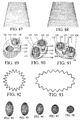
- Structures may also be formed from polygonal torsion/toroidal elements.
- the preferred use of such forms is as a body for a complex toroidal torsion element having internal shafts for the absorption of torsion stress, as shown in FIGS. 71-73 in one variation of which torsion stress is absorbed by multiple internal shafts 112.
- the shafts 112 are the point region of connection with other structural elements where they are not enclosed by the polygonal toroidal body 111 of the toroidal torsion element.
- the shafts 112 rotate on bearings 114 which are positioned by bearing mounts 113 which are fixedly attached to the body 111.
- a torque applied to turn the shaft 112 at its point of connection will induce a stress in the shaft 112 if the rotation of the shaft is restricted in some way.
- the shaft 112 to which the torque applied is connected at both ends to other shafts 112 by means of a universal joint 115 which transmits the torque to the other shafts 112. If the rotational motion of any of the shafts 112 are restricted, a torque on the shaft 112 will induce a torsional stress in the shaft 112, and the loading will be transmitted to adjacent shafts 112 by means of the universal joint 115 which connects them.
- a rotation block 116 Restriction of motion of a shaft 112 can be provided for by a rotation block 116, which is a means of fixing the end of a shaft 1 12 to the body 11 or of otherwise resisting rotation so that the end of the shaft 112 will not rotate freely.
- a rotation block 116 may be applied to the ends of a shaft 112 to which the torque may be applied where it is exposed for connection to other structural elements. If there are no rotational blocks the shafts will be free to rotate. If such free shafts are further connected by universal joints around the sides of the element, the torque will transmitted from the region of application to the other region of connection.
- polygonal torsion/toroidal elements may be connected in an array to form a structural module as shown in FIGS. 74-77 .
- the couplings used may be of the split block type shown in FIGS. 50-52 .
- a wide variation in form and combination is possible with polygonal torsion/toroidal elements.
- Polygonal torsion/toroidal elements may range from the pentagonal to the nonogonal, with the number of sides limited only by the application. Polygonal torsion/toroidal elements may be combined with other torsion/toroidal elements to form complex torsion/toroidal elements with structural features that can be tailored to any structural application.
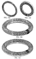
- connections between torsion/toroidal elements in which the torsion/toroidal elements remain outside of the peripheral tube of the other are a useful structural alternative to combination by constructing torsion/toroidal elements with coaxial tubes.
- FIGS. 78 and 79 Such a variation is shown in FIGS. 78 and 79 where the torsion/toroidal elements are coaxial, and in FIGS. 80 and 81 where the axes of the torsion/toroidal elements are angulated with each other.
- the structure which may be described as a "horizontal arch" is formed by a plurality of torsion/toroidal elements which are connected side-to-side on or in an arc of a curve in the horizontal plane, with adjacent members leaning together toward the center of curvature of the arc, as shown in FIG. 99 .
- the positions of the bottom of such torsion/toroidal elements are fixed at their base along the horizontal arc which describes the overall shape of the horizontal arch.
- Said positions are determined by the placement of each torsion/toroidal element so that the sides thereof are in contact, directly, or indirectly within a connection, above and within the perimeter of said arc of the horizontal arch.
- the torsion/toroidal members of the horizontal arch are thus forced together horizontally under the application of vertically downward loading near the top of each of the compression members.
- the horizontal arch may be employed as a part of successively vertically layered constructions as exemplified in FIGS.100 and 101 , in which each layer subjects the next layer below to vertically downward loading, such as in towers and multi-story buildings.
- the vertical loading of the "horizontal arch” layers forces the torsion/toroidal elements in each layer together horizontally, and adds to the horizontal cohesiveness of the structure, thus increasing its vertical load bearing strength.
- FIG. 84 another useful structural form is possible with the replication of a section as shown in FIG. 85 , and then connecting it in an appropriate scale to a torsion/toroidal element forming the spherical surface shown in FIG. 84 .
- the replication of the spherical section shown in FIG. 85 is applied once 141 and then again in smaller scale 142 to the first.
- This application of the spherical section shown in FIG. 85 can be made in replication to all of the torsion/toroidal elements that form the sphere, and yet again and again to all of the torsion/toroidal elements that form successive replications, until a practical limit is reached beyond which the process has no structural efficacy.
- Such a replicated spherical framework can be utilized as an implosion resistant pressure vessel, in which pressures interior to the vessel may be maintained at a lower level than the pressure outside the vessel.
- Torsion/toroidal elements may also be applied to create structures which are dynamic, with the constituent elements capable of movement by design, not only by deflection as a result of loading, but also by the active management of structural stresses. Torsion/toroidal elements may also be varied in shape dynamically so as to achieve alteration of the shape, size and volume of the structure of which they are constituent.
- structures such as buildings, bridges, even automobiles, seacraft, airframes and space frames are considered to be static structures in accordance with their manner of performance. That is, the expectation of performance for such structures is that they respond to the loads to which they are subjected by adequate management of the stress on the materials used and the means by which the materials are connected to comprise the structure.
- structures that are built with moving parts, such as a roof that opens by sliding or some other aperture that is created by actuation, manual or otherwise, as in the housing of an astronomical observatory.
- the present invention contemplates its application to create a dynamic structure, a structure in which the stress of the materials and their connections are managed by automated actuation of the coupling of torsion/toroidal elements and the shifting of the size and shape of structures by actuation of couplings.
- FIGS. 89-91 An example of an actuated coupling which can perform a fundamental shifting of shape is shown in FIGS. 89-91 , in which a motor 135 rotates a bearing 133 supported spline grip 132 by the rotational power it delivers to the drive 136 through the use of a transmission 134.
- the motor 135 When the motor 135 is powered, the spline grips 132 are driven, in a controlled manner to rotate and thus rotate a torsion element held in a grip in relation to the body 131 of the coupling, as well as any other torsion/toroidal element held in the other spline grip 132.
- FIGS. 92 and 93 The manner in which the change in shape of a 20 element array can be effected using such actuated couplings is demonstrated in FIGS. 92 and 93 .
- Couplings such as those described above and shown in FIGS. 89-91 (but not shown in FIGS. 92 and 93 ) would connect the torsion/toroidal elements, in the region of closest proximity of the elements, and would cause the angulation of the elements to change with sufficient precision so as to achieve the exact shape and size of the resulting structure required.
- Such a change of shape or size could be directed to take place in an organized way for all of the torsion/toroidal elements of the structure, including replicated substructures, which would result in a change of shape or size of the entire structure.
- An example of such an operation is shown in the schematic series of FIGS. 94-98 , where the frame of the surface of the prolate spheroid ( FIG.
- FIGS. 95-97 is transformed in stages ( FIGS. 95-97 ) to the frame of the surface of a sphere ( FIG. 98 ) by the changing of the shape of the constituent connected elliptical torsion/toroidal elements comprising the frame of the surface of the prolate sphere to more circular torsion/toroidal elements.
- This transformation results in a reduction of the volume bounded by the framework.
- Other transformations are possible, such as where the frame of surface of the sphere is transformed to the frame of the surface of an oblate spheroid, by the changing of the shape of the constituent connected torsion/toroidal elements comprising the frame of the surface of the sphere to more elliptical torsion/toroidal elements. This transformation would result in an increase in the volume bounded by the framework.
- a similar but isovolumetric pair of transformations is also possible, as is the reversal of the transformations described.
- This aspect of the present invention thus demonstrated for spheroids is a general property of the structural system.
- This can be demonstrated further, schematically, with the transformation of a plane array of connected torsion/toroidal elements to a connected array of torsion/toroidal elements in the surface of a paraboloid, which can be accomplished by a calculated and controlled changing of the shape of the constituent connected torsion/toroidal elements comprising the framework of the plane to more elliptical torsion/toroidal elements, variably to form the framework of the paraboloid.
- shape shifting may be used to alter the shape or size of any array of elements: not only those that provide the framework of surfaces, but also the framework of solids.
- the present invention may also be embodied in wheel and tire structures: as a torsion/toroidal wheel body, which has a toroidal shape without a central hub, and is the component that rotates in direct contact with the underlying surface or other wheels or rollers against and on which it may be operated or driven, as shown in FIG. 102 ; and as a tire structure that includes a circular array of a plurality of toroidal torsion support elements connected to form a toroidal shape, as shown in FIGS. 103 and 104 .
- the structure of the toroidal wheel body is the framework of toroidal torsion elements, as shown in FIGS. 19 , 87 and 88 , is self-supporting, and may be constructed to be flexible in order to conform to irregularities of surfaces.
- the toroidal wheel body need not be circular, and its shape may be continuously controlled by internal actuators, such as those shown in FIGS. 89-91 , to conform to the surface and to the drive mechanism.
- the toroidal wheel body framework may be used directly as a toroidal wheel body, or sheathed in a casing, as shown in FIG. 102 . Without a casing, the framework toroidal wheel body can operate on mud, sand, snow, or other loose material constituting the underlying surface.
- the tire structure may be used as an insert in a tire, as shown in FIG. 105 , incorporated directly in the structure of the tire body or carcass, as shown in FIG. 103 , or connected to a central band, as shown in FIG. 103 , or hub structure for receiving an axle to form a complete wheel structure.
- An object of this embodiment of the invention is to provide a non-pneumatic support for a wheel, as part of a non-pneumatic tire or as part of the wheel itself, which can be assisted with other pneumatic, fluidic, or mechanical means with inclusions of those means within the tube of the toroidal structure of the invention.
- the present invention provides a non-pneumatic tire support structure, it may also be used in conjunction with pneumatic, fluid filled, or other cushion elements.
- the open interior of the toroidal tube of the tire support structure also permits the inclusion of other types of toroidal structures within the toroidal tube, as shown in FIG. 34 , and to allow for other applications of the wheel and tire structure.
- any given toroidal element framework from other toroidal elements is commenced with the determination of the component curvatures of the required toroidal shape followed by the planning of the toroidal framework.
- a circular toroidal shape in one plane will have only one radius of curvature, the radius of the circular toroidal shape.
- a more complex toroidal shape, such as the elliptical toroid shown in FIGS. 35 and 36 will have more than one radius of curvature, the number depending on the number of elements to be used in the construction and the closeness of the approximation to the curvatures of the ellipse required.
- FIG. 106 is a schematic plan for construction of a toroidal framework with smaller toroidal elements 151 showing the dimensional quantities involved.
- the torus radius is RT
- the toroidal tube radius is Tr
- the number of elements is n
- the radius of a toroidal element is r
- RO RT + Tr
- RI RT-Tr
- Ro RO-r
- Ri RI + r
- Sin (Theta) r/Ri
- Sin (Psi) r/Ro
- Li r/Tan (Theta)
- Lo r/Tan (Psi)
- x Ro*Sin (Phi-Psi), (* indicating multiplication between adjacent quantities)
- Ld Ro * Cos (Phi-Psi)-Li
- Tan (Alpha) (x-r)/Ld
- Ej (dia) (x-r)/Sin (Alpha).
- the construction of the toroidal element framework may then be carried out by preparing a jig/mold for positioning the elements that constitute the toroidal framework from the specifications provided by the use of the toroidal element framework planning algorithm, positioning the constituent toroidal elements in the jig/mold, and connecting the constituent toroidal elements so positioned.
- a simple jig/mold for a toroidal framework in one plane may be prepared by inserting a series of pins 152 in a flat surface on which a plan as shown in FIG. 106 has been laid, the position of the pins outlining the positions of the constituent elements 151.
- the constituent elements may then be placed between the pins in the positions so outlined and then connected.
- the positions of the constituent elements may also be outlined by triangular or rectangular blocks, or other type of stop or clamp, or other means for positioning which hold or define the angles between the constituent elements in accordance with the plan for construction of the toroidal framework.
- Such other means of positioning also include depressions formed in the plan surface which could accommodate the constituent elements.
- the means for positioning may also be adjustable to conform to plans for construction of variously dimensioned toroidal frameworks with varying constituent elements.
- the connections may then be applied manually or with the use of robotics with the jig/mold containing the toroidal components stationary or in motion, rotational or otherwise.
- a jig/mold is also possible for non-flat surfaces using the same principles of construction therefor as described above, except that curvature in the additional dimension would have to be taken into account in setting the pins at the proper angles to the planes of tangency to the non-flat surface to properly position the toroidal elements to be connected.
- FIGS. 99-101 The progression of construction of a dome with toroidal elements is demonstrated for a dome with interleaved layers of toroidal elements in FIGS. 99-101 .
- the method of constructing such a dome commences with the determination of the shape of the base of the dome.
- the base may be circular or that of a more complex curve which may be approximated by segments of components with various curvatures.
- FIGS. 107 and 108 are schematic diagrams for construction of a dome framework with toroidal elements 163 showing the dimensional quantities involved.
- the vertical planes 161 and 162 are in the diagram only for the purpose of demonstrating the relationship among the dimensions of the dome framework and the toroidal elements of which it is constructed 163.
- the toroidal dome framework algorithm may be modified to assist in the planning of toroidal dome frameworks of interleaved and stacked layers for spheroid structures of virtually any base shape or elevation.
- the construction of the dome framework may then be carried out by connecting the toroidal elements of the sizes prescribed by the use of the toroidal dome framework planning algorithm at the locations on said toroidal elements indicated by the use of the toroidal dome framework planning algorithm, positioning the constituent toroidal elements according thereto, which may be facilitated by the use of a jig/mold from the specifications provided by the use of the toroidal dome framework planning algorithm, and connecting the constituent toroidal elements so positioned.
- the connections may then be applied manually or with the use of robotics.
- Such domes may also be joined in opposition at their bases to form complete or partial spheroid constructions.
- the best mode is the preferred embodiment of the present invention and employs toroidal elements that are constructed with the use of torsion elements which are toroidal in shape.
- the preferred embodiment using toroidal torsion elements converts most compression, tension and flexion loading of constructions using the system to torsional loading of the torsion elements of which the constructions are comprised.
- the use of toroidal torsion elements makes possible the construction of toroids which are self-supporting.
- the use of the invention includes every conceivable structure: bridges, towers, furniture, aircraft, land and sea vehicles, appliances, instruments, buildings, domes, airships, space structures and vehicles, and planetary and space habitats.
- the magnitude of such structures contemplated and made structurally and economically feasible by the system range from the minute to the gigantic.
- the structures that are possible with the use of the present invention are not limited to any particular design, and may even be freeform.
- Some of the structural forms can be applied to construct buildings for unstable foundation conditions and which can survive foundation movement and failure.
Landscapes
- Engineering & Computer Science (AREA)
- Architecture (AREA)
- Physics & Mathematics (AREA)
- Electromagnetism (AREA)
- Civil Engineering (AREA)
- Structural Engineering (AREA)
- Springs (AREA)
- Joining Of Building Structures In Genera (AREA)
- Wind Motors (AREA)
- Rolling Contact Bearings (AREA)
- Hydraulic Turbines (AREA)
- Shafts, Cranks, Connecting Bars, And Related Bearings (AREA)
- Vehicle Body Suspensions (AREA)
Abstract
Claims (6)
- Un système structurel d'éléments de torsion comprenant :(a) une pluralité d'éléments structurels ; et(b) des moyens de raccordement des éléments structurels, avec lesquels un cadre structurel est formé,caractérisé en ce que :lesdits éléments structurels fonctionnent avec torsion selon un mode de partage de charge ;au moins un desdits éléments structurels est un élément toroïdal, c'est-à-dire de la forme d'un tore ;lesdits moyens de raccordement des éléments structurels maintiennent les éléments structurels raccordés de telle sorte que la force de torsion sur l'un desdits éléments structurels est transmise à au moins l'un des autres dits éléments structurels ;le raccordement dudit élément toroïdal avec lesdits moyens de raccordement se fait de telle sorte que le tube dudit élément toroïdal et au moins un autre élément structurel sont maintenus dans une position l'un par rapport à l'autre aux endroits sur chacun desdits éléments structurels avec lesquels les moyens de raccordement sont en contact, et de telle sorte que la force de torsion créée par un couple de torsion appliqué pour tordre le tube dudit élément toroïdal est transmise le long du tube dudit élément toroïdal ;selon lequel la charge des éléments structurels est distribuée au sein du cadre structurel en tant qu'effort de torsion.
- Le système structurel de la revendication 1 dans lequel tous les éléments structurels ont une forme toroïdale.
- Le système structurel d'une quelconque des revendications 1 et 2 dans lequel un ou plusieurs des éléments structurels est un cadre d'éléments structurels qui fonctionnent avec torsion selon un mode de partage de charge.
- Le système structurel d'une quelconque des revendications 1 à 3 dans lequel les moyens de raccordement des éléments structurels sont des accouplements.
- Le système structurel d'une quelconque des revendications 1 à 4 dans lequel les moyens de raccordement des éléments structurels sont réglables de telle sorte que la position d'un ou plusieurs éléments structurels raccordés par lesdits moyens de raccordement puisse être changée par rapport aux autres éléments structurels qui sont raccordés audit ou auxdits éléments structurels par lesdits moyens de raccordement.
- Le système structurel d'une quelconque des revendications 1 à 5 dans lequel les moyens de raccordement des éléments structurels sont actionnés de telle sorte qu'un ou plusieurs éléments structurels puissent être déplacés par un raccordement puis maintenus par le raccordement dans la position qui résulte d'un tel déplacement, afin que l'élément structurel ne soit pas déplacé de manière substantielle lors du raccordement à moins qu'il soit à nouveau déplacé par le raccordement.
Applications Claiming Priority (11)
| Application Number | Priority Date | Filing Date | Title |
|---|---|---|---|
| US314267 | 1981-10-23 | ||
| US09/276,665 US6412232B1 (en) | 1999-03-26 | 1999-03-26 | Structural system of toroidal elements and method of construction therewith |
| US276666 | 1999-03-26 | ||
| US09/276,666 US6334284B1 (en) | 1999-03-26 | 1999-03-26 | Structural system of torsion elements and method of construction therewith |
| US276665 | 1999-03-26 | ||
| US09/307,985 US6253501B1 (en) | 1999-05-10 | 1999-05-10 | Horizontal arch |
| US307985 | 1999-05-10 | ||
| US09/314,267 US6516848B1 (en) | 1999-05-18 | 1999-05-18 | Toroidal wheel |
| US09/314,516 US6250355B1 (en) | 1999-05-19 | 1999-05-19 | Wheel and tire structure |
| US314516 | 1999-05-19 | ||
| PCT/US2000/007338 WO2000058575A1 (fr) | 1999-03-26 | 2000-03-20 | Systeme structurel d'elements de torsion/toroidaux et procedes de construction avec celui-ci |
Publications (3)
| Publication Number | Publication Date |
|---|---|
| EP1173644A1 EP1173644A1 (fr) | 2002-01-23 |
| EP1173644A4 EP1173644A4 (fr) | 2003-06-25 |
| EP1173644B1 true EP1173644B1 (fr) | 2011-08-31 |
Family
ID=27540605
Family Applications (1)
| Application Number | Title | Priority Date | Filing Date |
|---|---|---|---|
| EP00918149A Expired - Lifetime EP1173644B1 (fr) | 1999-03-26 | 2000-03-20 | Système structurel d'éléments de torsion/toroidaux |
Country Status (13)
| Country | Link |
|---|---|
| EP (1) | EP1173644B1 (fr) |
| JP (1) | JP2002541360A (fr) |
| CN (1) | CN1142348C (fr) |
| AP (1) | AP1751A (fr) |
| AT (1) | ATE522673T1 (fr) |
| AU (1) | AU770845B2 (fr) |
| BR (1) | BR0010775A (fr) |
| CA (1) | CA2367090C (fr) |
| EA (1) | EA003037B1 (fr) |
| MX (1) | MXPA01009703A (fr) |
| NZ (1) | NZ514075A (fr) |
| OA (1) | OA11921A (fr) |
| WO (1) | WO2000058575A1 (fr) |
Families Citing this family (8)
| Publication number | Priority date | Publication date | Assignee | Title |
|---|---|---|---|---|
| US6729984B2 (en) * | 2001-07-28 | 2004-05-04 | Rhino Toys, Inc. | Toy ball apparatus |
| US20050115187A1 (en) * | 2002-02-06 | 2005-06-02 | Shinichi Sunahara And Kenichi Sunahara | Building structure |
| NL2006545C2 (nl) * | 2011-04-05 | 2012-10-08 | Daedalissimo N V | Werkwijze voor het vervaardigen van een schaalvormige constructie, een constructie-element en een constructie. |
| CN102383630A (zh) * | 2011-09-15 | 2012-03-21 | 金华市农业科学研究院 | 一种葡萄架顶的停车棚 |
| CN103466062B (zh) * | 2013-09-10 | 2016-03-30 | 上海大学 | 水下潜器的魔球变换平衡机构 |
| CN105155670A (zh) * | 2015-10-07 | 2015-12-16 | 徐林波 | 一种模块化组合建筑 |
| CN105971120A (zh) * | 2016-05-25 | 2016-09-28 | 徐林波 | 板式组装建筑 |
| CN107119801A (zh) * | 2017-05-23 | 2017-09-01 | 同济大学建筑设计研究院(集团)有限公司 | 一种轮辐式张拉结构拓展体系库构建方法 |
Family Cites Families (10)
| Publication number | Priority date | Publication date | Assignee | Title |
|---|---|---|---|---|
| US1706215A (en) * | 1926-01-26 | 1929-03-19 | American Safety Device Co | Adjustable coupling means |
| US3763910A (en) * | 1971-12-23 | 1973-10-09 | E Hawes | Resilient wheel |
| US3959937A (en) * | 1974-06-17 | 1976-06-01 | Leonard Spunt | Modular dome structure |
| US4005520A (en) * | 1976-03-09 | 1977-02-01 | Sanford Arthur C | Frame structure fabricating system |
| US4057207A (en) * | 1976-04-08 | 1977-11-08 | John Paul Hogan | Space vehicle module |
| US4679361A (en) * | 1986-01-13 | 1987-07-14 | Yacoe J Craig | Polyhedral structures that approximate a sphere |
| US4784172A (en) * | 1987-06-25 | 1988-11-15 | Yacoboni Joseph D | Instant emergency shelter |
| US4884790A (en) * | 1988-06-01 | 1989-12-05 | Paul Castrilli | Nonlinear torsion spring |
| US5038532A (en) * | 1989-10-10 | 1991-08-13 | University Of New Mexico | Deployable spatial structure |
| US5427443A (en) * | 1992-11-27 | 1995-06-27 | Bridgestone Corporation | Annular elastic track |
-
2000
- 2000-03-20 AT AT00918149T patent/ATE522673T1/de not_active IP Right Cessation
- 2000-03-20 WO PCT/US2000/007338 patent/WO2000058575A1/fr active IP Right Grant
- 2000-03-20 BR BR0010775-1A patent/BR0010775A/pt active Pending
- 2000-03-20 EP EP00918149A patent/EP1173644B1/fr not_active Expired - Lifetime
- 2000-03-20 NZ NZ514075A patent/NZ514075A/en unknown
- 2000-03-20 CN CNB008055556A patent/CN1142348C/zh not_active Expired - Fee Related
- 2000-03-20 OA OA1200100244A patent/OA11921A/en unknown
- 2000-03-20 CA CA2367090A patent/CA2367090C/fr not_active Expired - Fee Related
- 2000-03-20 MX MXPA01009703A patent/MXPA01009703A/es active IP Right Grant
- 2000-03-20 AP APAP/P/2001/002280A patent/AP1751A/en active
- 2000-03-20 EA EA200101004A patent/EA003037B1/ru not_active IP Right Cessation
- 2000-03-20 AU AU39012/00A patent/AU770845B2/en not_active Ceased
- 2000-03-20 JP JP2000608844A patent/JP2002541360A/ja active Pending
Non-Patent Citations (1)
| Title |
|---|
| None * |
Also Published As
| Publication number | Publication date |
|---|---|
| EA200101004A1 (ru) | 2002-04-25 |
| JP2002541360A (ja) | 2002-12-03 |
| CN1142348C (zh) | 2004-03-17 |
| BR0010775A (pt) | 2003-07-15 |
| CA2367090C (fr) | 2012-02-14 |
| EA003037B1 (ru) | 2002-12-26 |
| NZ514075A (en) | 2003-10-31 |
| CN1345393A (zh) | 2002-04-17 |
| AU770845B2 (en) | 2004-03-04 |
| AP1751A (en) | 2007-06-29 |
| OA11921A (en) | 2006-04-12 |
| WO2000058575B1 (fr) | 2000-11-30 |
| AU3901200A (en) | 2000-10-16 |
| CA2367090A1 (fr) | 2000-10-05 |
| AP2001002280A0 (en) | 2001-09-30 |
| ATE522673T1 (de) | 2011-09-15 |
| MXPA01009703A (es) | 2003-06-24 |
| WO2000058575A1 (fr) | 2000-10-05 |
| EP1173644A4 (fr) | 2003-06-25 |
| EP1173644A1 (fr) | 2002-01-23 |
Similar Documents
| Publication | Publication Date | Title |
|---|---|---|
| EP0986685B1 (fr) | Structure tridimensionnelle a treillis isometrique | |
| US8651059B2 (en) | Finfish containment pens and polyhedral structures | |
| US6192634B1 (en) | Dual network dome structure | |
| AU723114B2 (en) | Modular fiber-reinforced composite structural member | |
| US4974986A (en) | Connector for variable-shape spaceframe structural system | |
| EA005355B1 (ru) | Конструктивный элемент и способ его образования | |
| US4092992A (en) | Laminated arch members and method of constructing them | |
| EP1173644B1 (fr) | Système structurel d'éléments de torsion/toroidaux | |
| US6334284B1 (en) | Structural system of torsion elements and method of construction therewith | |
| WO1997028327A9 (fr) | Element structurel modulaire,composite et renforce par des fibres | |
| US6412232B1 (en) | Structural system of toroidal elements and method of construction therewith | |
| EP1527294B1 (fr) | Structures pressurisables presentant differentes sections de surfaces | |
| JP6101686B2 (ja) | 上向きに凸状の立体フレームとその構成方法 | |
| JPS61270583A (ja) | 複合トワイン構造の製造装置 | |
| JP2002542410A (ja) | ドーム構造 | |
| CN111255155A (zh) | 一种预应力增强膜结构体及组合式预应力增强膜结构体 | |
| KR101129842B1 (ko) | 다축 연결 조인트 및 이를 이용한 아치형 하우스 구조물 | |
| JP3171226B2 (ja) | トラスベース構造物におけるフレーム弦材のジョイント部材体 | |
| EP4182569A1 (fr) | Filetage de clé et systèmes de filetage de clé | |
| JPH01178631A (ja) | シェル構造物の成形方法および格子ユニットの連結構造 | |
| JPH0274748A (ja) | プレストレストコンクリート柱およびその製造方法 | |
| WO1990006409A1 (fr) | Arcs de voute | |
| JPH0726630A (ja) | 曲面屋根の架構体 | |
| JPH09100570A (ja) | トラス用組立ハブ体およびそれを用いたトラスベースの接合構造 |
Legal Events
| Date | Code | Title | Description |
|---|---|---|---|
| PUAI | Public reference made under article 153(3) epc to a published international application that has entered the european phase |
Free format text: ORIGINAL CODE: 0009012 |
|
| 17P | Request for examination filed |
Effective date: 20011018 |
|
| AK | Designated contracting states |
Kind code of ref document: A1 Designated state(s): AT BE CH CY DE DK ES FI FR GB GR IE IT LI LU MC NL PT SE |
|
| AX | Request for extension of the european patent |
Free format text: AL;LT;LV;MK;RO;SI |
|
| A4 | Supplementary search report drawn up and despatched |
Effective date: 20030509 |
|
| RIC1 | Information provided on ipc code assigned before grant |
Ipc: 7E 04B 1/38 A Ipc: 7B 25G 3/38 B Ipc: 7E 04B 1/344 B |
|
| 17Q | First examination report despatched |
Effective date: 20030829 |
|
| 17Q | First examination report despatched |
Effective date: 20030829 |
|
| 17Q | First examination report despatched |
Effective date: 20030829 |
|
| GRAP | Despatch of communication of intention to grant a patent |
Free format text: ORIGINAL CODE: EPIDOSNIGR1 |
|
| RTI1 | Title (correction) |
Free format text: STRUCTURAL SYSTEM OF TORSION/TOROIDAL ELEMENTS |
|
| GRAS | Grant fee paid |
Free format text: ORIGINAL CODE: EPIDOSNIGR3 |
|
| GRAA | (expected) grant |
Free format text: ORIGINAL CODE: 0009210 |
|
| RAP1 | Party data changed (applicant data changed or rights of an application transferred) |
Owner name: PROVITOLA, ANTHONY I. |
|
| RIN1 | Information on inventor provided before grant (corrected) |
Inventor name: PROVITOLA, ANTHONY I. |
|
| AK | Designated contracting states |
Kind code of ref document: B1 Designated state(s): AT BE CH CY DE DK ES FI FR GB GR IE IT LI LU MC NL PT SE |
|
| REG | Reference to a national code |
Ref country code: CH Ref legal event code: EP Ref country code: GB Ref legal event code: FG4D |
|
| REG | Reference to a national code |
Ref country code: IE Ref legal event code: FG4D |
|
| REG | Reference to a national code |
Ref country code: DE Ref legal event code: R096 Ref document number: 60046403 Country of ref document: DE Effective date: 20111103 |
|
| REG | Reference to a national code |
Ref country code: NL Ref legal event code: VDEP Effective date: 20110831 |
|
| PG25 | Lapsed in a contracting state [announced via postgrant information from national office to epo] |
Ref country code: SE Free format text: LAPSE BECAUSE OF FAILURE TO SUBMIT A TRANSLATION OF THE DESCRIPTION OR TO PAY THE FEE WITHIN THE PRESCRIBED TIME-LIMIT Effective date: 20110831 Ref country code: NL Free format text: LAPSE BECAUSE OF FAILURE TO SUBMIT A TRANSLATION OF THE DESCRIPTION OR TO PAY THE FEE WITHIN THE PRESCRIBED TIME-LIMIT Effective date: 20110831 Ref country code: FI Free format text: LAPSE BECAUSE OF FAILURE TO SUBMIT A TRANSLATION OF THE DESCRIPTION OR TO PAY THE FEE WITHIN THE PRESCRIBED TIME-LIMIT Effective date: 20110831 |
|
| REG | Reference to a national code |
Ref country code: AT Ref legal event code: MK05 Ref document number: 522673 Country of ref document: AT Kind code of ref document: T Effective date: 20110831 |
|
| PG25 | Lapsed in a contracting state [announced via postgrant information from national office to epo] |
Ref country code: AT Free format text: LAPSE BECAUSE OF FAILURE TO SUBMIT A TRANSLATION OF THE DESCRIPTION OR TO PAY THE FEE WITHIN THE PRESCRIBED TIME-LIMIT Effective date: 20110831 Ref country code: GR Free format text: LAPSE BECAUSE OF FAILURE TO SUBMIT A TRANSLATION OF THE DESCRIPTION OR TO PAY THE FEE WITHIN THE PRESCRIBED TIME-LIMIT Effective date: 20111201 Ref country code: CY Free format text: LAPSE BECAUSE OF FAILURE TO SUBMIT A TRANSLATION OF THE DESCRIPTION OR TO PAY THE FEE WITHIN THE PRESCRIBED TIME-LIMIT Effective date: 20110831 |
|
| PG25 | Lapsed in a contracting state [announced via postgrant information from national office to epo] |
Ref country code: BE Free format text: LAPSE BECAUSE OF FAILURE TO SUBMIT A TRANSLATION OF THE DESCRIPTION OR TO PAY THE FEE WITHIN THE PRESCRIBED TIME-LIMIT Effective date: 20110831 |
|
| PG25 | Lapsed in a contracting state [announced via postgrant information from national office to epo] |
Ref country code: IT Free format text: LAPSE BECAUSE OF FAILURE TO SUBMIT A TRANSLATION OF THE DESCRIPTION OR TO PAY THE FEE WITHIN THE PRESCRIBED TIME-LIMIT Effective date: 20110831 Ref country code: PT Free format text: LAPSE BECAUSE OF FAILURE TO SUBMIT A TRANSLATION OF THE DESCRIPTION OR TO PAY THE FEE WITHIN THE PRESCRIBED TIME-LIMIT Effective date: 20120102 |
|
| PG25 | Lapsed in a contracting state [announced via postgrant information from national office to epo] |
Ref country code: DK Free format text: LAPSE BECAUSE OF FAILURE TO SUBMIT A TRANSLATION OF THE DESCRIPTION OR TO PAY THE FEE WITHIN THE PRESCRIBED TIME-LIMIT Effective date: 20110831 |
|
| PLBE | No opposition filed within time limit |
Free format text: ORIGINAL CODE: 0009261 |
|
| STAA | Information on the status of an ep patent application or granted ep patent |
Free format text: STATUS: NO OPPOSITION FILED WITHIN TIME LIMIT |
|
| 26N | No opposition filed |
Effective date: 20120601 |
|
| REG | Reference to a national code |
Ref country code: DE Ref legal event code: R097 Ref document number: 60046403 Country of ref document: DE Effective date: 20120601 |
|
| PG25 | Lapsed in a contracting state [announced via postgrant information from national office to epo] |
Ref country code: MC Free format text: LAPSE BECAUSE OF NON-PAYMENT OF DUE FEES Effective date: 20120331 |
|
| REG | Reference to a national code |
Ref country code: CH Ref legal event code: PL |
|
| REG | Reference to a national code |
Ref country code: IE Ref legal event code: MM4A |
|
| PG25 | Lapsed in a contracting state [announced via postgrant information from national office to epo] |
Ref country code: IE Free format text: LAPSE BECAUSE OF NON-PAYMENT OF DUE FEES Effective date: 20120320 Ref country code: CH Free format text: LAPSE BECAUSE OF NON-PAYMENT OF DUE FEES Effective date: 20120331 Ref country code: LI Free format text: LAPSE BECAUSE OF NON-PAYMENT OF DUE FEES Effective date: 20120331 |
|
| PG25 | Lapsed in a contracting state [announced via postgrant information from national office to epo] |
Ref country code: ES Free format text: LAPSE BECAUSE OF FAILURE TO SUBMIT A TRANSLATION OF THE DESCRIPTION OR TO PAY THE FEE WITHIN THE PRESCRIBED TIME-LIMIT Effective date: 20111211 |
|
| PG25 | Lapsed in a contracting state [announced via postgrant information from national office to epo] |
Ref country code: LU Free format text: LAPSE BECAUSE OF NON-PAYMENT OF DUE FEES Effective date: 20120320 |
|
| REG | Reference to a national code |
Ref country code: FR Ref legal event code: PLFP Year of fee payment: 17 |
|
| PGFP | Annual fee paid to national office [announced via postgrant information from national office to epo] |
Ref country code: DE Payment date: 20160309 Year of fee payment: 17 |
|
| PGFP | Annual fee paid to national office [announced via postgrant information from national office to epo] |
Ref country code: GB Payment date: 20160219 Year of fee payment: 17 Ref country code: FR Payment date: 20160311 Year of fee payment: 17 |
|
| REG | Reference to a national code |
Ref country code: DE Ref legal event code: R119 Ref document number: 60046403 Country of ref document: DE |
|
| GBPC | Gb: european patent ceased through non-payment of renewal fee |
Effective date: 20170320 |
|
| REG | Reference to a national code |
Ref country code: FR Ref legal event code: ST Effective date: 20171130 |
|
| PG25 | Lapsed in a contracting state [announced via postgrant information from national office to epo] |
Ref country code: FR Free format text: LAPSE BECAUSE OF NON-PAYMENT OF DUE FEES Effective date: 20170331 Ref country code: DE Free format text: LAPSE BECAUSE OF NON-PAYMENT OF DUE FEES Effective date: 20171003 |
|
| PG25 | Lapsed in a contracting state [announced via postgrant information from national office to epo] |
Ref country code: GB Free format text: LAPSE BECAUSE OF NON-PAYMENT OF DUE FEES Effective date: 20170320 |