EP1173325B1 - Presse pour le traitement de matieres morcelees, en particulier dechets ou ordures, comportant une fraction de matieres susceptibles de fluer sous l'effet d'une pression - Google Patents
Presse pour le traitement de matieres morcelees, en particulier dechets ou ordures, comportant une fraction de matieres susceptibles de fluer sous l'effet d'une pression Download PDFInfo
- Publication number
- EP1173325B1 EP1173325B1 EP00918948A EP00918948A EP1173325B1 EP 1173325 B1 EP1173325 B1 EP 1173325B1 EP 00918948 A EP00918948 A EP 00918948A EP 00918948 A EP00918948 A EP 00918948A EP 1173325 B1 EP1173325 B1 EP 1173325B1
- Authority
- EP
- European Patent Office
- Prior art keywords
- extrusion chamber
- piston
- extrusion
- shutter
- materials
- Prior art date
- Legal status (The legal status is an assumption and is not a legal conclusion. Google has not performed a legal analysis and makes no representation as to the accuracy of the status listed.)
- Expired - Lifetime
Links
- 239000000463 material Substances 0.000 title claims abstract description 69
- 239000002699 waste material Substances 0.000 title claims abstract description 6
- 230000000694 effects Effects 0.000 title claims description 5
- 238000001125 extrusion Methods 0.000 claims abstract description 217
- 238000006073 displacement reaction Methods 0.000 claims abstract description 19
- 238000000605 extraction Methods 0.000 claims abstract description 13
- 238000007789 sealing Methods 0.000 claims abstract description 10
- 238000011144 upstream manufacturing Methods 0.000 claims description 35
- 239000007787 solid Substances 0.000 claims description 18
- 230000006835 compression Effects 0.000 claims description 17
- 238000007906 compression Methods 0.000 claims description 17
- 239000002131 composite material Substances 0.000 claims description 7
- 230000002093 peripheral effect Effects 0.000 claims description 7
- 238000011049 filling Methods 0.000 claims description 4
- 238000003825 pressing Methods 0.000 claims description 3
- 238000012545 processing Methods 0.000 claims description 2
- 230000001105 regulatory effect Effects 0.000 claims 1
- 230000000284 resting effect Effects 0.000 claims 1
- 238000011068 loading method Methods 0.000 description 18
- 238000003304 gavage Methods 0.000 description 7
- 238000013461 design Methods 0.000 description 6
- 238000012423 maintenance Methods 0.000 description 6
- 210000004907 gland Anatomy 0.000 description 5
- 239000002994 raw material Substances 0.000 description 5
- 238000010008 shearing Methods 0.000 description 5
- 238000000034 method Methods 0.000 description 4
- 239000002028 Biomass Substances 0.000 description 3
- 235000021183 entrée Nutrition 0.000 description 3
- 230000008569 process Effects 0.000 description 3
- 230000008901 benefit Effects 0.000 description 2
- 230000008859 change Effects 0.000 description 2
- 238000002485 combustion reaction Methods 0.000 description 2
- 230000004069 differentiation Effects 0.000 description 2
- 239000000446 fuel Substances 0.000 description 2
- 235000011837 pasties Nutrition 0.000 description 2
- 238000000926 separation method Methods 0.000 description 2
- 241001415961 Gaviidae Species 0.000 description 1
- 229910000831 Steel Inorganic materials 0.000 description 1
- 238000005299 abrasion Methods 0.000 description 1
- 230000000712 assembly Effects 0.000 description 1
- 238000000429 assembly Methods 0.000 description 1
- 238000012550 audit Methods 0.000 description 1
- 230000004323 axial length Effects 0.000 description 1
- 230000015572 biosynthetic process Effects 0.000 description 1
- 230000000903 blocking effect Effects 0.000 description 1
- 238000005056 compaction Methods 0.000 description 1
- 230000000295 complement effect Effects 0.000 description 1
- 239000002361 compost Substances 0.000 description 1
- 230000008030 elimination Effects 0.000 description 1
- 238000003379 elimination reaction Methods 0.000 description 1
- 238000000855 fermentation Methods 0.000 description 1
- 230000004151 fermentation Effects 0.000 description 1
- 239000003337 fertilizer Substances 0.000 description 1
- 239000007789 gas Substances 0.000 description 1
- 230000005484 gravity Effects 0.000 description 1
- 238000005470 impregnation Methods 0.000 description 1
- 238000003754 machining Methods 0.000 description 1
- 238000004519 manufacturing process Methods 0.000 description 1
- 230000005012 migration Effects 0.000 description 1
- 238000013508 migration Methods 0.000 description 1
- 238000010899 nucleation Methods 0.000 description 1
- 210000000056 organ Anatomy 0.000 description 1
- 238000007747 plating Methods 0.000 description 1
- 230000009467 reduction Effects 0.000 description 1
- 239000010959 steel Substances 0.000 description 1
- 238000003860 storage Methods 0.000 description 1
Images



Classifications
-
- B—PERFORMING OPERATIONS; TRANSPORTING
- B30—PRESSES
- B30B—PRESSES IN GENERAL
- B30B9/00—Presses specially adapted for particular purposes
- B30B9/02—Presses specially adapted for particular purposes for squeezing-out liquid from liquid-containing material, e.g. juice from fruits, oil from oil-containing material
- B30B9/26—Permeable casings or strainers
-
- B—PERFORMING OPERATIONS; TRANSPORTING
- B30—PRESSES
- B30B—PRESSES IN GENERAL
- B30B9/00—Presses specially adapted for particular purposes
- B30B9/02—Presses specially adapted for particular purposes for squeezing-out liquid from liquid-containing material, e.g. juice from fruits, oil from oil-containing material
- B30B9/04—Presses specially adapted for particular purposes for squeezing-out liquid from liquid-containing material, e.g. juice from fruits, oil from oil-containing material using press rams
- B30B9/06—Presses specially adapted for particular purposes for squeezing-out liquid from liquid-containing material, e.g. juice from fruits, oil from oil-containing material using press rams co-operating with permeable casings or strainers
-
- B—PERFORMING OPERATIONS; TRANSPORTING
- B30—PRESSES
- B30B—PRESSES IN GENERAL
- B30B9/00—Presses specially adapted for particular purposes
- B30B9/02—Presses specially adapted for particular purposes for squeezing-out liquid from liquid-containing material, e.g. juice from fruits, oil from oil-containing material
- B30B9/04—Presses specially adapted for particular purposes for squeezing-out liquid from liquid-containing material, e.g. juice from fruits, oil from oil-containing material using press rams
- B30B9/06—Presses specially adapted for particular purposes for squeezing-out liquid from liquid-containing material, e.g. juice from fruits, oil from oil-containing material using press rams co-operating with permeable casings or strainers
- B30B9/067—Presses specially adapted for particular purposes for squeezing-out liquid from liquid-containing material, e.g. juice from fruits, oil from oil-containing material using press rams co-operating with permeable casings or strainers with a retractable abutment member closing one end of the press chamber
Definitions
- the invention relates to a press for processing materials. fragmented, in particular waste or garbage, containing a fraction of materials likely to flow under pressure.
- this combustible fraction free of moisture and biomass can be stored for an indefinite period without any nuisance, especially in heaps on open air areas, to be used by combustion during periods with very high energy demands.
- the fermentable fraction freed from non-fermentable materials can, for its part, be treated under conditions optimal by known methods, in particular by biological seeding and fermentation to produce composts, organic fertilizers or gases likely to provide heat energy.
- the length of the elements of the frame subject to the forces of the thrust to the extrusion pressure is very important, of the order of 5 to 6 meters, which requires to provide elements of structure very strongly dimensioned without being able to guarantee against a tendency to deformation of these elements.
- the booster piston is a heavy and expensive element. because it must exercise very different functions consisting, on the one hand, in feeding the extrusion chamber, function during which it moves over a long stroke by exerting a slight push, and on the other hand, exerting pressure extrusion in a very short time.
- a press such as this has been designed as described in European patent application EP-684 117, comprising a barrel rotary in which three uniformly distributed extrusion chambers are provided around the axis of said barrel, and three filling stations respectively raw material, compression of this material, and extraction of the solid fraction compressed, in front of which are successively brought the extrusion chambers by rotation of the barrel.
- the length of the frame subjected to the efforts of the pushing to the extrusion pressure is advantageously reduced.
- this reduction is obtained in particular through the realization of a heavy rotary element which in practice turns out to lead to a relatively complex design with a high cost price, and leading at high maintenance and upkeep costs.
- the present invention aims to overcome the aforementioned drawbacks of current presses and aims to provide a design press simplified with a lighter structure compared to current presses and requiring reduced operating costs.
- the idea behind the invention was to make a press designed so that the functions, on the one hand, of filling the chamber extraction and, on the other hand, pressurization and extraction of the material fully separated, thus exempting significant effort from the part the longest of the press, i.e. the one devoted to loading.
- this separation is obtained by providing the press of a shutter adapted to seal the upstream face of the extrusion chamber when the material is pressurized, so that the thrust exerted on this shutter is reflected on an element of the frame immediately juxtaposed audit shutter.
- the length of the part of the frame intended to compensate for the efforts of pressurization is limited to the axial length occupied by the chamber during extrusion. This design therefore reduces notably the length of the structural elements subjected to significant efforts and the risks of deformation of these elements, and therefore authorizes much lighter presses with production costs and reduced operation.
- the pressurization is carried out by a pressure piston having to exert significant efforts but traveling only one weak stroke.
- the end of the piston presser is kept constantly inside the extrusion chamber, so that all problems of wear and shearing of the materials are eliminated extrude inherent in the entry and exit of conventional pistons.
- the compressed fraction is ejected thanks to the axial displacement of the extrusion chamber along the pressure piston maintained in its deployed position, displacement which can be obtained easily seen the low relative weight of said extrusion chamber.
- the means for moving the extrusion chamber have the function, in addition to ejection function, to seal this extrusion chamber while maintaining the upstream face of the latter pressed against the shutter when setting pressure.
- the press includes an annular seal integral with the shutter and diameter combined with that of the upstream face of the chamber extrusion, adapted to be compressed in the sealing position of this last.
- the supply means which can be of any type known per se (piston, Archimedes screw), have the sole function of supplying the extrusion chamber and does not participate in any way in the following pressurization operations and extraction.
- This limitation of the functions devolved to the supply means advantageously leads to making it possible to "lighten” the latter because they do not have to create or undergo significant efforts, and thus reduce the length to less than 2 meters elements of the frame subjected to the efforts of pressurizing extrusion.
- the pressure piston advantageously has a diameter smaller than the internal diameter of the extrusion chamber, the downstream face of said extrusion chamber being closed by a wall integral with the latter, pierced with an orifice of diameter conjugate with that of said pressure piston.
- the pressure piston advantageously also has a domed end section in the shape of a cap.
- a convex form of the end of the pressing piston makes it possible to obtain at any time but mainly to approaching the end of the race, i.e. approaching obtaining pressure final, a compression of the residual mass, then little Pascalian, more important in the center than on the outskirts. This arrangement thus facilitates the migration of the last pasty materials, the most linked to the residue, towards the orifices and towards the free space between the piston and the wall of the extrusion chamber.
- each orifice of the extrusion chamber incorporates a removable jacket, said extrusion chamber being provided with means for holding each of the shirts in its orifice.
- each orifice of the extrusion chamber has advantageously a counterbore made at the level of the external face of the wall peripheral of said extrusion chamber, while each jacket has a collar shaped to accommodate the counterbore of the corresponding orifice.
- the means for holding the shirts comprises then an annular skirt of suitable shape to accommodate the extrusion chamber, pierced radial orifices arranged so as to each extend in the radial extension an orifice of said extrusion chamber.
- annular skirt in addition to its function of blocking shirts allowing their change after removal of said skirt, allows consolidate the enclosure by forming a hoop.
- Each orifice of this annular skirt has, in addition, advantageously a frustoconical shape of increasing section in the direction of the face external of said annular skirt, so as to reduce the "blunt" wear which is observed in practice.
- routing means do not have to create or undergo internal chamber pressure they do not have to be adjusted to the supply duct, but can on the contrary, be of dimensions smaller than those of this conduit. Therefore, are thus eliminated, on the one hand, the shearing of the materials at the entry of the conduit feed or extrusion chamber, and secondly, the subjugations of a bore pushed interfaces and fouling of those interfaces.
- the element of frame consists of a flat wall parallel to the upstream face of the extrusion chamber, adapted to form the bottom wall of a shutter guide slide, and pierced with a hole coaxial with the axis (x).
- the shutter advantageously comprises a wall of length greater than the diameter of the extrusion chamber, and has a portion of length consisting of a solid surface wall suitable for sealing the face upstream of said extrusion chamber, during this obturation and to pass on the frame member pushing the pressure piston and the extrusion chamber, and a wall of length pierced with an orifice of conjugate dimensions of said upstream face arranged to be positioned coaxially with axis (x), in the open position said shutter.
- Such a shutter has a shape suitable for driving, during its movement towards its closed position, a quantity of materials to process with a volume smaller than that of the orifice provided in said obturator, because the routing means having already compacted the load of raw materials, the returns in background material will be limited. Any amount of material that remains in the orifice would then be driven in priority in the extrusion chamber during the next sequence.
- the shutter also advantageously comprises a contour portion posterior, considering the direction of movement of said shutter from its position opening towards its closed position, presenting an oblique profile inclined in direction of the frame element.
- the guide means longitudinal of the boost piston consist of the bottom wall of the hopper load having a section in the shape of a circular sector of diameter conjugate with that of said booster piston.
- the maneuvering means of the boost piston include control means adapted to allow to adjust the positioning of the end of said booster piston in the position retracted from the latter.
- control means adapted to allow to adjust the positioning of the end of said booster piston in the position retracted from the latter.
- the drive means in rotation of the worm comprises control means adapted to allow to adjust the number of turns made by said worm during each supply operation of the extrusion chamber. This provision has an objective identical to that for adjusting the retracted position of the boost piston.
- the hopper of loading and the extrusion chamber are carried by two separate frames sealed on a common base and connected by the connecting pipe, said connecting pipe being consisting of two longitudinal sections respectively secured to one and the other frames, and joined by means of a flexible junction.
- the structures of the two parts of the assembly, feed and extrusion devices, subject to very constraints are separate. Indeed and in particular due to the differences in diameters between the pistons and / or screws and the cylinders, the rigor of their alignment does not require the more compactness of a common structure, necessarily more rigid due to its length, and therefore heavier and more expensive.
- control unit includes a manual control adapted to generate a withdrawal additional pressure piston, from its retracted position, to extract the end of said pressure piston of the extrusion chamber.
- This additional withdrawal pressure piston allows, in fact, to extract it from the extrusion chamber in view any disassembly of the latter.
- control unit is advantageously a controllable unit adapted to allow the progression of the climb to be programmed in pressure, the value of the final pressure, and the duration of maintenance of said pressure final. Indeed, certain results or characteristics of separate materials depend of these parameters.
- controllable press unit will allow the choice of the pressure rise curve, for example by controlling the flow rate of the pumps of the hydraulic power unit, as well as the choice of the final pressure and the duration of its maintenance.
- the progressiveness will be more or less rapid, possibly comprising one or more sequences leading to the final extrusion pressure.
- the pressure progression curve will be experimentally determinable according to the materials to be treated.
- the final pressure determines the dryness of the solid residue, which can be more or less sought, particularly in the case where the residue after extrusion must be stored and / or used as fuel.
- the press according to the invention shown in Figure 1 is composed of two subsets sealed on a common base S of masonry army forming a non-deformable whole: a loading sub-assembly of materials, and a subset of extruding these materials.
- the extrusion sub-assembly is supported by a frame comprising two end plates such as 1, conventional elements of chassis, such as tie rods 2, and longitudinal plates such as 3 in the form of angles possibly intended to reinforce the rigidity of the assembly, and giving press a general rectangular parallelepiped shape.
- These plates longitudinal 3 are, moreover, adapted so that each of the lateral faces, lower and upper, has an opening such as 4 extending over the major length of said face, for the purposes explained below.
- This extrusion sub-assembly includes an extrusion chamber 5 cylindrical with horizontal axis of revolution (x), delimited on the one hand, by two faces open, called upstream 5a and downstream 5b, and on the other hand, by a peripheral wall perforated which has a plurality of radial extrusion orifices such as 6.
- each extrusion orifice 6 has a counterbore 6a formed at the level of the external face of the peripheral wall.
- each of these orifices 6 incorporates a cylindrical jacket 7 comprising a collar 7a of shape suitable for accommodating in the counterbore 6a.
- This extrusion chamber 5 is, moreover, "shrunk” by a annular skirt 8, ensuring the maintenance of the shirts 7, and pierced opposite each extrusion orifices 6 of a radial orifice 9 of frustoconical shape of section increasing towards the outer face of said annular skirt.
- tapered orifices 9 open into a collector annular 10 provided with a lower discharge duct 11 which delivers the materials extruded to a conveyor belt 12 disposed in a pit 13 formed in the base 5 while a second conveyor belt 14 is intended to receive the residue extrusion.
- the downstream face 5b of the extrusion chamber 5 is also partially closed by a plate 15 having a circular orifice coaxial with the axis (x) of diameter less than the diameter of said extrusion chamber bordered by a peripheral engraving housing an annular seal 15a.
- the extrusion chamber / collector assembly 9 is, moreover, adapted to be able to move axially between the end plates 1 and is carried for this purpose by two lateral raceways such as 16. This displacement is, moreover, generated by two cylinders 17, 18 diametrically distributed under and above the extrusion chamber 5 and coupled to the closure plate 15.
- the extrusion sub-assembly also includes a piston 19 of diameter combined with that of the orifice of the closure plate 15, provided with a convex end 19a in the form of a spherical cap or the top of a paraboloid.
- This pressure piston 19 is moved by a jack 20 adapted for the move between a deployed position inside the extrusion chamber 5 and a retracted position where it remains inside the latter.
- This sub-assembly finally includes a suitable shutter 21 for alternately closing and opening the upstream face Sa of the extrusion chamber 5.
- This shutter 21 consists of a wall adapted to move in a slide vertical 22 open at its upper and lower ends, and whose plate upstream end 1 of the press forms the bearing face, said wall being associated with this effect to a jack 23.
- This wall 21 comprises, firstly, a portion bottom of full surface 21a of dimensions adapted to seal the upstream face 5a of the extrusion chamber 5 and to serve as a support for the upstream end face of the peripheral wall of the latter.
- This portion of solid surface comprises, in in addition, an annular groove housing a seal 24 adapted to be compressed by the extrusion chamber 5 when the latter is caused to be pressed against the shutter 21.
- This wall 21 further comprises an upper portion 21b pierced with a circular orifice 25 with a diameter at least equal to that of the upstream face 5a of the extrusion chamber 5, adapted to be aligned with the latter in cylinder retracted position 23.
- the lower edge 25a of this orifice 25 also has a oblique profile inclined towards the end plate 1, so as to favor the possible shearing of the materials which would have come out of the extrusion chamber 5 after force-feeding.
- the extrusion sub-assembly includes a conduit 26 for connection with the material loading sub-assembly, said conduit extending coaxially with the axis (x) in the extension of an orifice circular of the same diameter formed in the upstream end plate 1.
- the loading sub-assembly includes a loading hopper 27, the section of which has a general dihedral shape the edge of which is replaced by a cylindrical sector 27a of diameter smaller than that of the connecting pipe 26.
- This loading hopper 27 further comprises a downstream lower opening in the extension of which extends a duct 28 connected to the connection conduit 26 by a flexible seal 29, and of the same diameter than the latter.
- This loading hopper 27 also has an orifice upstream allowing the deflections of a boost piston 30 driven by a jack 31, and diameter combined with that of the cylindrical sector formed by the bottom 27a of said hopper, but lower than that of conduits 26, 28 in order to avoid shearing of materials.
- This loading hopper 27 finally comprises a gland longitudinal 32 of conventional type intended to avoid the formation of a vault and to cause some compaction of the material in the lower portion of said hopper swept by the boost piston 30.
- Press components described above are ordered by a programmable controller and adapted to move as follows.
- the two cylinders 17, 18 are arranged to move the extrusion chamber 5 axially between a retracted position where this the latter is distant from the shutter 21 by a distance adapted to allow the fall on the conveyor belt 14 of the extrusion residues, and a deployed position where the upstream face Sa of said extrusion chamber is in contact with said shutter.
- the cylinder 20 is adapted to move the piston 19 between a deployed position in which it spans most of the length of said extrusion chamber, and a retracted position where its end 19a remains in this extrusion chamber 5, near the downstream face 5b of the latter.
- the programmable controller has a control manual which leads to a complementary withdrawal of the piston 19 allowing extract the end 19a of the latter from the extrusion chamber 5, in view authorize the withdrawal of the extrusion chamber 5 / collector 9 assembly through the opening chassis for maintenance of this assembly.
- the chassis comprises, on the one hand, side openings allowing access to all of the organs located inside the latter, in particular the raceways 16, and on the other hand, a lower opening by which the extruded materials and the extrusion residues are discharged.
- the jack 31 is finally adapted to move the booster piston 30 between a variable retracted position in which the end of this piston 30 is located upstream opening side of the loading hopper 27, and a deployed position where this end penetrates a short distance into the extrusion chamber 5.
- variable retracted position of this booster piston 30 controlled from the programmable unit allows selection of the quantity of materials which will be introduced into the extrusion chamber 5 during each sequence.
- the boost piston 30 includes a diameter smaller than that of the conduits 26, 28 and of the extrusion chamber 5 because that it does not have to seal this extrusion chamber or compensate for the pressure from the pressure piston 19. This feature leads to the elimination, on the one hand, of the shears at the inlet of the duct 28 and of the extrusion chamber 5, and on the other hand, the subjections of the deep bore of the interfaces and the fouling of the latter.
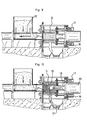
- the machine is in particular programmed to condition the operating cycle illustrated in Figures 7 to 12 and described below.
- the press is assumed to be in the following initial position: booster piston 30 and pressure piston 19 in their retracted position, chamber extrusion 5 in its deployed position in flexible support against the shutter 21, shutter 21 in its open position, and plugger 32 in its low position.
- the boost piston 30 is deployed so as to sweep at least a portion of the loading hopper 27 and push a quantity of raw materials (determined by adjusting its "O" position) in the extrusion chamber 5, the front face 5b of which is closed by the pressure piston 19 (figure 7).
- the boost piston 30 is retracted to its "O" position, while that the gland 32 is raised and the shutter 21 moved to its closed position of the extrusion chamber 5 ( Figure 8).
- the cylinders 17, 18 exert a significant force intended to press the upstream face Sa of the extrusion chamber 5 against the shutter 21, and at thus allow the radial sealing between these elements by compression of the joint seal 24 ( Figure 9).
- the gland 32 is lowered so as to compact the raw material in the bottom of the loading hopper 27.
- the pressure piston 19 is deployed according to an evolution of programmed pressure until a final pressure, also programmed from compression, of the materials contained in the extrusion chamber 5 (FIG. 10). At during this compression, the extruded materials are further removed by the conduit 11 towards the conveyor belt 12.
- the extrusion chamber 5 is then brought back to its position deployed but without exerting an effort likely to prevent displacement shutter 21 which is itself brought to its low open position (figure 12). Simultaneously, the pressure piston 19 is returned to its retracted position.
Landscapes
- Engineering & Computer Science (AREA)
- Mechanical Engineering (AREA)
- Processing Of Solid Wastes (AREA)
- Refuse Collection And Transfer (AREA)
- Meat, Egg Or Seafood Products (AREA)
Description
- une chambre d'extrusion d'axe longitudinal (x) montée sur un bâti, d'une part, ouverte à ses deux extrémités selon des sections droites définissant deux faces opposées coaxiales, une face, dite face amont, d'entrée des matières et une face, dite face aval, et, d'autre part percée d'orifices d'extrusion sur sa périphérie,
- des moyens d'alimentation de la chambre d'extrusion, aptes à délivrer une quantité de matières à l'intérieur de ladite chambre d'extrusion, au travers de la face amont de cette dernière,
- des moyens de compression des matières renfermées dans la chambre d'extrusion, aptes à soumettre ces dernières à une compression dans des conditions propres à en extraire par extrusion les matières susceptibles de fluer et à former une fraction solide compressée, lesdits moyens de compression comprenant un piston, dit piston presseur, coaxial avec l'axe (x) de la chambre d'extrusion, associé à des moyens de manoeuvre agencés pour le déplacer entre une position rétractée où il libère la chambre d'extrusion et une position déployée où il pénètre dans ladite chambre d'extrusion jusqu'à l'obtention d'une pression prédéterminée,
- et des moyens d'extraction de la fraction solide compressée dans la chambre d'extrusion,
- les moyens de compression des matières composites
comprennent, en outre :
- un obturateur mobile interposé entre la face amont de la chambre d'extrusion et un élément du bâti, associé à des moyens de déplacement aptes à le déplacer parallèlement à ladite face amont, alternativement entre une position d'obturation dans laquelle il est en appui sur ledit élément de bâti, et une position d'ouverture de ladite chambre d'extrusion,
- les moyens de manoeuvre du piston presseur sont adaptés pour que dans la position rétractée de ce dernier, l'extrémité dudit piston presseur demeure à l'intérieur de la chambre d'extrusion, au voisinage de la face aval de cette dernière.
- les moyens d'extraction de la fraction solide de matières comprennent des moyens de déplacement axial de la chambre d'extrusion aptes à l'amener à coulisser le long du piston presseur disposé dans sa position déployée, entre une position, dite position d'étanchement, où la face amont de ladite chambre d'extrusion est plaquée contre l'obturateur, et une position, dite position d'extraction, dans laquelle ladite face amont est éloignée axialement d'une distance prédéterminée dudit obturateur.
- une trémie de chargement dotée d'un orifice de sortie coaxial avec l'axe (x) et relié au bâti par un conduit de liaison,
- des moyens d'acheminement des matières à l'intérieur de la chambre d'extrusion au travers du conduit de liaison.
- un piston, dit piston de gavage, coaxial avec la chambre d'extrusion et de diamètre inférieur à celui de ladite chambre d'extrusion, ledit piston de gavage étant agencé pour se déplacer entre une position rétractée où son extrémité est située au voisinage d'une ouverture de la trémie de chargement opposée à l'ouverture de sortie, et une position extrême déployée où il traverse la trémie de chargement, le conduit de liaison, et pénètre dans la chambre d'extrusion sur une faible longueur déterminée de celle-ci,
- des moyens de manoeuvre du piston de gavage,
- et des moyens de guidage longitudinal du piston de gavage.
- une vis sans fin disposée dans le fond de la trémie de chargement et dotée d'une extrémité, dite extrémité aval, positionnée sensiblement dans un même plan que l'élément du bâti,
- des moyens d'entraínement en rotation de la vis sans fin.
- actionnement des moyens d'alimentation de la chambre d'extrusion en vue de remplir celle-ci d'une quantité donnée de matières composites,
- actionnement des moyens de déplacement de l'obturateur jusqu'à amener ce dernier dans sa position d'obturation de la face d'entrée de la chambre d'extrusion.
- actionnement des moyens de déplacement axial de la chambre d'extrusion en vue d'exercer un effort de placage de la face d'entrée de cette dernière contre l'obturateur.
- déploiement du piston presseur dans la chambre d'extrusion jusqu'à atteindre une pression finale prédéterminée en vue d'assurer la compression requise des matières.
- actionnement des moyens de déplacement axial de la chambre d'extrusion jusqu'à amener cette dernière dans sa position d'extraction, en vue d'éjecter la fraction solide compressée.
- actionnement des moyens de déplacement de l'obturateur jusqu'à amener ce dernier dans sa position d'ouverture.
- actionnement des moyens de déplacement axial de la chambre d'extrusion jusqu'à ramener cette dernière en butée souple contre l'obturateur.
- retrait du piston presseur jusqu'à sa position rétractée.
- la progressivité de la montée en pression ainsi que le niveau et la durée d'application de la pression finale d'extrusion, contribuent à déterminer le rendement ou la sélectivité de la séparation des matières fluentes.
- la figure 1 est une vue longitudinale partiellement en coupe par un plan vertical axial d'une presse conforme à l'invention,
- la figure 2 en est une coupe transversale par un plan vertical A,
- la figure 3 est une vue frontale de l'obturateur de cette presse,
- la figure 4 est une coupe longitudinale axiale de la chambre d'extrusion de cette presse,
- la figure 5 est une coupe longitudinale partielle à échelle agrandie d'une portion de paroi périphérique de la chambre d'extrusion,
- la figure 6 est une coupe transversale par un plan vertical B de la trémie de chargement de cette presse,
- et les figures 7 à 12 sont des vues longitudinales schématiques partiellement en coupe montrant les étapes essentielles du cycle de fonctionnement de la presse.
- d0 la densité de la matière brute dans la trémie de chargement 27,
- d1 la densité dans le bas de la trémie 27, obtenue sous l'effet du fouloir 32, avant que la matière soit poussée dans les conduits 26, 28 (position "O" du chargeur),
- d2 la densité dans la chambre d'extrusion 5 avant extrusion,
- d3 la densité du résidu de l'extrusion,
- impossibilité de mouvement pour le piston de gavage 30 si :
- l'obturateur 21 n'est pas en position complète d'ouverture de la chambre d'extrusion 5,
- la chambre d'extrusion 5 n'est pas en position déployée,
- le piston presseur 19 n'est pas en position rétractée,
- impossibilité de fermeture par l'obturateur 21 si le piston de gavage 30 est en mouvement vers l'aval et s'il n'est pas hors de la chambre d'extrusion 5,
- impossibilité d'ouverture par l'obturateur 21 si les vérins 17, 18 de manoeuvre de la chambre d'extrusion 5 exercent sur lui la pression d'étanchement,
- impossibilité d'une avancée du piston presseur 19 si :
- la chambre d'extrusion 5 n'exerce pas sur le joint d'étanchement radial 24 la poussée nécessaire à l'étanchéité de ladite chambre d'extrusion,
- l'obturateur 21 n'est pas complètement en position de fermeture.
Claims (20)
- Presse pour le traitement de matières morcelées, en particulier ordures ou déchets, comportant une fraction de matières susceptibles de fluer sous l'effet d'une pression, comprenant :ladite presse étant caractérisée en ce que :un bâti (1-3),une chambre d'extrusion (5) d'axe longitudinal (x) montée sur ledit bâti (1-3), d'une part, ouverte à ses deux extrémités selon des sections droites définissant deux faces opposées coaxiales, une face (5a), dite face amont, d'entrée des matières et une face (5b), dite face aval, et, d'autre part, percée d'orifices d'extrusion (6) sur sa périphérie,des moyens (26-31) d'alimentation de la chambre d'extrusion (5), aptes à délivrer une quantité de matières à l'intérieur de ladite chambre d'extrusion, au travers de la face amont (5a) de cette dernière,des moyens de compression des matières renfermées dans la chambre d'extrusion (5) aptes à soumettre ces dernières à une compression dans des conditions propres à en extraire par extrusion les matières susceptibles de fluer et à former une fraction solide compressée, lesdits moyens de compression comprenant des moyens de manoeuvre (20) et un piston (19), dit piston presseur, coaxial avec l'axe (x) de la chambre d'extrusion (5), associé aux moyens de manoeuvre (20) agencés pour déplacer le piston presseur (19) entre une position rétractée où il libère la chambre d'extrusion (5) et une position déployée où il pénètre dans ladite chambre d'extrusion jusqu'à l'obtention d'une pression prédéterminée,et des moyens (17, 18) d'extraction de la fraction solide compressée dans la chambre d'extrusion (5),les moyens de compression des matières composites comprennent, en outre :un obturateur mobile (21), interposé entre la face amont (5a) de la chambre d'extrusion (5) et un élément (1) du bâti, et des moyens de déplacement (23) aptes à déplacer l'obturateur mobile (21) parallèlement par rapport à ladite face amont, alternativement entre une position d'obturation dans laquelle il est en appui sur ledit élément de bâti, et une position d'ouverture de ladite chambre d'extrusion,les moyens de manoeuvre (20) du piston presseur (19) sont adaptés pour que dans la position rétractée de ce dernier, l'extrémité (19a) dudit piston presseur demeure à l'intérieur de la chambre d'extrusion (5), au voisinage de la face aval (5b) de cette dernière,les moyens d'extraction de la fraction solide de matières comprennent des moyens (17, 18) de déplacement axial de la chambre d'extrusion (5) aptes à l'amener à coulisser le long du piston presseur (19) disposé dans sa position déployée, entre une position, dite position d'étanchement, où la face amont (5a) de ladite chambre d'extrusion est plaquée contre l'obturateur (21), et une position, dite position d'extraction, dans laquelle ladite face amont est éloignée axialement d'une distance prédéterminée dudit obturateur.
- Presse selon la revendication 1, caractérisée en ce que le piston presseur (19) présente un diamètre inférieur au diamètre interne de la chambre d'extrusion (5), la face aval (5b) de ladite chambre d'extrusion étant obturée par une paroi (15) solidarisée à cette dernière, percée d'un orifice de diamètre conjugué de celui dudit piston presseur.
- Presse selon la revendication 2, caractérisée en ce que le piston presseur (19) présente un tronçon d'extrémité bombé (19a) en forme de calotte.
- Presse selon l'une des revendications 1 ou 3, caractérisée en ce qu'elle comprend un joint d'étanchéité annulaire (24) solidaire de l'obturateur (21) et de diamètre conjugué de celui de la face amont (5a) de la chambre d'extrusion (5), adapté pour être comprimé dans la position d'étanchement de cette dernière.
- Presse selon l'une des revendications précédentes, caractérisée en ce que chaque orifice (6) de la chambre d'extrusion incorpore une chemise amovible (7), ladite chambre d'extrusion étant dotée de moyens (8) de maintien de chacune des chemises dans son orifice (6).
- Presse selon la revendication 5, caractérisée en ce que :chaque orifice (6) de la chambre d'extrusion (5) comporte un lamage (6a) ménagé au niveau de la face externe de la paroi périphérique de ladite chambre d'extrusion,chaque chemise (7) comporte un collet (7a) de forme adaptée pour se loger dans le lamage (6a) de l'orifice (6) correspondant,les moyens de maintien des chemises (7) comprennent une jupe annulaire (8) de forme adaptée pour loger la chambre d'extrusion (5), percée d'orifices radiaux (9) ménagés de façon à s'étendre chacun dans le prolongement radial d'un orifice (6) de ladite chambre d'extrusion.
- Presse selon la revendication 6, caractérisée en ce que chaque orifice (9) de la jupe annulaire (8) présente une forme tronconique de section croissante en direction de la face externe de ladite jupe annulaire.
- Presse selon l'une des revendications précédentes, caractérisée en ce que les moyens d'alimentation de la chambre d'extrusion comprennent :une trémie de chargement (27) dotée d'un orifice de sortie coaxial avec l'axe (x) et relié au bâti (1-3) par un conduit de liaison (26, 28),des moyens (30) d'acheminement des matières à l'intérieur de la chambre d'extrusion (5) au travers du conduit de liaison (26, 28).
- Presse selon la revendication 8, caractérisée en ce que l'élément du bâti (1) consiste en une paroi plane parallèle à la face amont (Sa) de la chambre d'extrusion (5), adaptée pour former la paroi de fond d'une glissière (22) de guidage de l'obturateur (21), et percée d'un orifice coaxial avec l'axe (x).
- Presse selon l'une des revendications 8 ou 9, caractérisée en ce que l'obturateur (21) comporte une paroi de longueur supérieure au diamètre de la chambre d'extrusion (5), et présente une portion de longueur consistant en une paroi pleine (21a) de surface adaptée pour obturer la face amont (5a) de ladite chambre d'extrusion et, lors de cette obturation, pour répercuter sur l'élément de bâti (1) la poussée du piston presseur (19) et de la chambre d'extrusion (5), et une portion de paroi (21b) percée d'un orifice (22) de dimensions conjuguées de ladite face amont, agencé pour être positionné coaxialement avec l'axe (x), dans la position d'ouverture dudit obturateur.
- Presse selon la revendication 10, caractérisée en ce que l'orifice (22) de l'obturateur (21) comporte une porion de contour postérieure (22a), en considérant le sens de déplacement dudit obturateur de sa position d'ouverture vers sa position d'obturation, présentant un profil oblique incliné en direction de l'élément de bâti (1).
- Presse selon l'une des revendications 8 à 11, caractérisée en ce que les moyens d'acheminement des matières à l'intérieur de la chambre d'extrusion (5) comprennent :un piston (30), dit piston de gavage, coaxial avec la chambre d'extrusion (5) et de diamètre inférieur à celui de ladite chambre d'extrusion, ledit piston de gavage étant agencé pour se déplacer entre une position rétractée où son extrémité est située au voisinage d'une ouverture de la trémie de chargement (27) opposée à l'ouverture de sortie, et une position extrême déployée où il traverse la trémie de chargement (27), le conduit de liaison (26, 28), et pénètre dans la chambre d'extrusion (5) sur une faible longueur déterminée de celle-ci,des moyens (31) de manoeuvre du piston de gavage (30),et des moyens (27a) de guidage longitudinal du piston de gavage (30).
- Presse selon la revendication 12, caractérisée en ce que les moyens de guidage longitudinal du piston de gavage sont constitués par la paroi de fond (27a) de la trémie de chargement (27) présentant une section en forme de secteur circulaire de diamètre conjugué de celui dudit piston de gavage.
- Presse selon l'une des revendications 12 ou 13, caractérisée en ce que les moyens de manoeuvre du piston de gavage (30) comprennent des moyens de commande adaptés pour permettre de régler le positionnement de l'extrémité dudit piston de gavage dans la position rétractée de ce dernier.
- Presse selon l'une des revendications 8 à 11, caractérisée en ce que les moyens d'acheminement des matières à l'intérieur de la chambre d'extrusion (5) comprennent :une vis sans fin disposée dans le fond de la trémie de chargement (27) et dotée d'une extrémité, dite extrémité aval, positionnée sensiblement dans un même plan que l'élément du bâti (1),des moyens d'entraínement en rotation de la vis sans fin.
- Presse selon la revendication 15, caractérisée en ce que les moyens d'entraínement en rotation de la vis sans fin comprennent des moyens de commande adaptés pour permettre de régler le nombre de tours effectué par ladite vis sans fin lors de chaque opération d'alimentation de la chambre d'extrusion (5).
- Presse selon l'une des revendications 8 à 16, caractérisée en ce que la trémie de chargement (27) et la chambre d'extrusion (5) sont portées par deux bâtis distincts scellés sur un socle commun (S) et reliés par le conduit de liaison (26, 28), ledit conduit de liaison étant constitué de deux tronçons longitudinaux respectivement solidaires de l'un et l'autre des bâtis, et réunis au moyen d'une jonction souple (29).
- Presse selon l'une des revendications précédentes, caractérisée en ce qu'elle comprend une unité de commande adaptée pour conditionner le cycle de fonctionnement suivant, à partir d'une position initiale où le piston presseur (19) est dans sa position rétractée, l'obturateur (21) dans sa position d'ouverture, et la chambre d'extrusion (5) positionnée avec sa face d'entrée amont (5a) accolée audit obturateur.actionnement des moyens d'alimentation (30) de la chambre d'extrusion (5) en vue de remplir celle-ci d'une quantité donnée de matières composites,actionnement des moyens de déplacement (23) de l'obturateur (21) jusqu'à amener ce dernier dans sa position d'obturation de la face d'entrée (5a) de la chambre d'extrusion (5),actionnement des moyens de déplacement axial (17, 18) de la chambre d'extrusion (5) en vue d'exercer un effort de placage de la face d'entrée (5a) de cette dernière contre l'obturateur (21),déploiement du piston presseur (19) dans la chambre d'extrusion (5) jusqu'à atteindre une pression finale prédéterminée en vue d'assurer la compression requise des matières,actionnement des moyens de déplacement axial (17, 18) de la chambre d'extrusion (5) jusqu'à amener cette dernière dans sa position d'extraction, en vue d'éjecter la fraction solide compressée,actionnement des moyens de déplacement (23) de l'obturateur (21) jusqu'à amener ce dernier dans sa position d'ouverture,actionnement des moyens de déplacement axial (17, 18) de la chambre d'extrusion (5) jusqu'à ramener cette dernière en butée souple contre l'obturateur (21),retrait du piston presseur (19) jusqu'à sa position rétractée.
- Presse selon la revendication 18, caractérisée en ce que l'unité de commande comprend une commande manuelle adaptée pour engendrer un retrait supplémentaire du piston presseur (19), à partir de sa position rétractée, en vue d'extraire l'extrémité (19a) dudit piston presseur de la chambre d'extrusion (5).
- Presse selon l'une des revendications 18 ou 19, caractérisée en ce que l'unité de commande est une unité pilotable adaptée pour permettre de programmer la progression de la montée en pression, la valeur de la pression finale, et la durée de maintien de ladite pression finale.
Applications Claiming Priority (3)
| Application Number | Priority Date | Filing Date | Title |
|---|---|---|---|
| FR9905240A FR2792570B1 (fr) | 1999-04-26 | 1999-04-26 | Presse pour le traitement de matieres morcelees, en particulier dechets ou ordures, comportant une fraction de matieres susceptibles de fluer sous l'effet d'une pression |
| FR9905240 | 1999-04-26 | ||
| PCT/FR2000/000931 WO2000064665A1 (fr) | 1999-04-26 | 2000-04-11 | Presse pour le traitement de matieres morcelees, en particulier dechets ou ordures, comportant une fraction de matieres susceptibles de fluer sous l'effet d'une pression |
Publications (2)
| Publication Number | Publication Date |
|---|---|
| EP1173325A1 EP1173325A1 (fr) | 2002-01-23 |
| EP1173325B1 true EP1173325B1 (fr) | 2003-07-09 |
Family
ID=9544846
Family Applications (1)
| Application Number | Title | Priority Date | Filing Date |
|---|---|---|---|
| EP00918948A Expired - Lifetime EP1173325B1 (fr) | 1999-04-26 | 2000-04-11 | Presse pour le traitement de matieres morcelees, en particulier dechets ou ordures, comportant une fraction de matieres susceptibles de fluer sous l'effet d'une pression |
Country Status (8)
| Country | Link |
|---|---|
| EP (1) | EP1173325B1 (fr) |
| AT (1) | ATE244634T1 (fr) |
| AU (1) | AU3972200A (fr) |
| BR (1) | BR0009997A (fr) |
| DE (1) | DE60003806T2 (fr) |
| ES (1) | ES2202095T3 (fr) |
| FR (1) | FR2792570B1 (fr) |
| WO (1) | WO2000064665A1 (fr) |
Cited By (1)
| Publication number | Priority date | Publication date | Assignee | Title |
|---|---|---|---|---|
| US10589486B2 (en) | 2013-10-13 | 2020-03-17 | Anaergia B.V. | Device and method for pressing organic material out of waste |
Families Citing this family (6)
| Publication number | Priority date | Publication date | Assignee | Title |
|---|---|---|---|---|
| IT1320861B1 (it) * | 2000-12-15 | 2003-12-10 | Vm Press Srl | Procedimento e impianto di trattamento di rifiuti solidi urbani. |
| ITTO20040109A1 (it) * | 2004-02-26 | 2004-05-26 | Vm Press Srl | Macchina per la compattazione di rifiuti |
| ITTO20040108A1 (it) * | 2004-02-26 | 2004-05-26 | Vm Press Srl | Macchina per la compattazione di rifiuti |
| DE102008039773A1 (de) * | 2008-08-26 | 2010-03-04 | Gebr. Jäcklin GmbH Maschinen- und Getriebebau | Schleifschlammpresse |
| ITTO20120456A1 (it) * | 2012-05-25 | 2013-11-26 | Vm Press Srl | Processo per la produzione di gas combustibile da rifiuti solidi urbani. |
| DE102018120529A1 (de) | 2018-06-29 | 2020-01-02 | Technische Universität Bergakademie Freiberg | Verfahren zur Herstellung von Presslingen und Anordnung zur Herstellung von Presslingen |
Family Cites Families (8)
| Publication number | Priority date | Publication date | Assignee | Title |
|---|---|---|---|---|
| GB1542257A (en) * | 1976-12-02 | 1979-03-14 | Nat Res Dev | Presses |
| US4208188A (en) * | 1978-03-22 | 1980-06-17 | Signet Corporation | Consolidation of coal slurry |
| CH628837A5 (fr) * | 1979-03-27 | 1982-03-31 | Bema Engineering Sa | Procede de compression separatrice de dechets, appareil pour la mise en oeuvre de ce procede, brique et boue resultant de ce procede et utilisation de cette boue. |
| FR2577167A1 (fr) * | 1985-02-08 | 1986-08-14 | Eloy Maurice | Presse a separation de phases |
| FR2615444A1 (fr) * | 1987-05-22 | 1988-11-25 | Falguieres Hubert | Porte sectionneuse a coulissement vertical pour pressoir de produits agricoles ou similaires |
| FR2670711A1 (fr) * | 1990-12-21 | 1992-06-26 | Dumons Pierre | Procede de traitement d'ordures ou dechets et presse perfectionnee pour sa mise en óoeuvre. |
| EP0552083B1 (fr) * | 1992-01-13 | 1997-04-02 | Jean-Michel Egretier | Pressoir performant pour produits divers |
| EP0684117A1 (fr) * | 1994-05-25 | 1995-11-29 | TECNOECO S.r.l. | Machine pour traitement des matériaux humides, spécialement pour le recyclage des ordures ménagères |
-
1999
- 1999-04-26 FR FR9905240A patent/FR2792570B1/fr not_active Expired - Fee Related
-
2000
- 2000-04-11 ES ES00918948T patent/ES2202095T3/es not_active Expired - Lifetime
- 2000-04-11 EP EP00918948A patent/EP1173325B1/fr not_active Expired - Lifetime
- 2000-04-11 AU AU39722/00A patent/AU3972200A/en not_active Abandoned
- 2000-04-11 WO PCT/FR2000/000931 patent/WO2000064665A1/fr not_active Ceased
- 2000-04-11 BR BR0009997-0A patent/BR0009997A/pt not_active Application Discontinuation
- 2000-04-11 AT AT00918948T patent/ATE244634T1/de not_active IP Right Cessation
- 2000-04-11 DE DE60003806T patent/DE60003806T2/de not_active Expired - Lifetime
Cited By (2)
| Publication number | Priority date | Publication date | Assignee | Title |
|---|---|---|---|---|
| US10589486B2 (en) | 2013-10-13 | 2020-03-17 | Anaergia B.V. | Device and method for pressing organic material out of waste |
| US11458701B2 (en) | 2013-10-13 | 2022-10-04 | Anaergia B.V. | Device and method for pressing organic material out of waste |
Also Published As
| Publication number | Publication date |
|---|---|
| ES2202095T3 (es) | 2004-04-01 |
| FR2792570B1 (fr) | 2001-07-13 |
| EP1173325A1 (fr) | 2002-01-23 |
| ATE244634T1 (de) | 2003-07-15 |
| DE60003806T2 (de) | 2004-06-03 |
| WO2000064665A1 (fr) | 2000-11-02 |
| BR0009997A (pt) | 2002-01-08 |
| FR2792570A1 (fr) | 2000-10-27 |
| DE60003806D1 (de) | 2003-08-14 |
| AU3972200A (en) | 2000-11-10 |
Similar Documents
| Publication | Publication Date | Title |
|---|---|---|
| EP0563173B1 (fr) | Procede de traitement d'ordures ou dechets et presse perfectionnee pour sa mise en oeuvre | |
| EP3325248B1 (fr) | Dispositif et procede de nettoyage d'une extrudeuse pour melanges d'elastomeres | |
| EP0016734A1 (fr) | Procédé de compression séparatrice de déchets, appareil pour la mise en oeuvre de ce procédé | |
| EP0468852B1 (fr) | Presse de traitement de déchets | |
| FR2671514A1 (fr) | Presse de compactage et de traitement de dechets. | |
| EP1173325A1 (fr) | Presse pour le traitement de matieres morcelees, en particulier dechets ou ordures, comportant une fraction de matieres susceptibles de fluer sous l'effet d'une pression | |
| FR2563704A1 (fr) | Dispositif de pressoir a double piston et a action alternative | |
| EP0468853B1 (fr) | Presse de traitement de déchets hétérogènes | |
| FR2551361A1 (fr) | Procede de fabrication de granules en utilisant une machine a faire des comprimes | |
| CH619640A5 (fr) | ||
| EP0377000B1 (fr) | Installation de dosage et de transport a flux unidirectionnel | |
| EP2364594B1 (fr) | Procédé de division de pâte en pâtons | |
| EP0518715B1 (fr) | Presse pour déchets hétérogènes | |
| FR2629754A1 (fr) | Pressoir pneumatique | |
| FR2582985A1 (fr) | Pressoir alternatif a piston | |
| FR2507530A1 (fr) | Ensemble d'injection pour machine a mouler les matieres plastiques | |
| FR3097230A1 (fr) | Installation de traitement, notamment pour le traitement par fermentation de déchets organiques | |
| FR2616378A1 (fr) | Presse pour presser par charges separees des particules presentees sous la forme d'une matiere en vrac et contenant des proportions d'un fluide liquide et/ou gazeux | |
| FR3091560A1 (fr) | Pompe a piston pour digesteur anaerobie | |
| EP0091365A1 (fr) | Procédé et dispositif pour la séparation de phases pour des matériaux rigides multiphasés | |
| FR2511935A1 (fr) | Machine pour compacter les rafles de mais | |
| FR2902292A1 (fr) | Procede de division volumetrique de pate et son dispositif de mise en oeuvre | |
| FR2610246A1 (fr) | Presse a separation de phases | |
| EP0211706A2 (fr) | Procédé et dispositif pour séparer des fractions liquides et solides, notamment de jus de fruits | |
| FR2529135A1 (fr) | Pressoir pour pressurer des produits agricoles |
Legal Events
| Date | Code | Title | Description |
|---|---|---|---|
| PUAI | Public reference made under article 153(3) epc to a published international application that has entered the european phase |
Free format text: ORIGINAL CODE: 0009012 |
|
| 17P | Request for examination filed |
Effective date: 20011009 |
|
| AK | Designated contracting states |
Kind code of ref document: A1 Designated state(s): AT BE CH CY DE DK ES FI FR GB GR IE IT LI LU MC NL PT SE |
|
| GRAH | Despatch of communication of intention to grant a patent |
Free format text: ORIGINAL CODE: EPIDOS IGRA |
|
| GRAH | Despatch of communication of intention to grant a patent |
Free format text: ORIGINAL CODE: EPIDOS IGRA |
|
| GRAA | (expected) grant |
Free format text: ORIGINAL CODE: 0009210 |
|
| AK | Designated contracting states |
Designated state(s): AT BE CH CY DE DK ES FI FR GB GR IE IT LI LU MC NL PT SE |
|
| PG25 | Lapsed in a contracting state [announced via postgrant information from national office to epo] |
Ref country code: FI Free format text: LAPSE BECAUSE OF FAILURE TO SUBMIT A TRANSLATION OF THE DESCRIPTION OR TO PAY THE FEE WITHIN THE PRESCRIBED TIME-LIMIT Effective date: 20030709 Ref country code: CY Free format text: LAPSE BECAUSE OF FAILURE TO SUBMIT A TRANSLATION OF THE DESCRIPTION OR TO PAY THE FEE WITHIN THE PRESCRIBED TIME-LIMIT Effective date: 20030709 Ref country code: AT Free format text: LAPSE BECAUSE OF FAILURE TO SUBMIT A TRANSLATION OF THE DESCRIPTION OR TO PAY THE FEE WITHIN THE PRESCRIBED TIME-LIMIT Effective date: 20030709 Ref country code: IE Free format text: LAPSE BECAUSE OF FAILURE TO SUBMIT A TRANSLATION OF THE DESCRIPTION OR TO PAY THE FEE WITHIN THE PRESCRIBED TIME-LIMIT Effective date: 20030709 Ref country code: NL Free format text: LAPSE BECAUSE OF FAILURE TO SUBMIT A TRANSLATION OF THE DESCRIPTION OR TO PAY THE FEE WITHIN THE PRESCRIBED TIME-LIMIT Effective date: 20030709 |
|
| REG | Reference to a national code |
Ref country code: GB Ref legal event code: FG4D Free format text: NOT ENGLISH |
|
| REG | Reference to a national code |
Ref country code: CH Ref legal event code: EP |
|
| RAP2 | Party data changed (patent owner data changed or rights of a patent transferred) |
Owner name: D.M.S. |
|
| RIN2 | Information on inventor provided after grant (corrected) |
Inventor name: DUMONS, PIERRE |
|
| REF | Corresponds to: |
Ref document number: 60003806 Country of ref document: DE Date of ref document: 20030814 Kind code of ref document: P |
|
| REG | Reference to a national code |
Ref country code: IE Ref legal event code: FG4D Free format text: FRENCH |
|
| REG | Reference to a national code |
Ref country code: CH Ref legal event code: NV Representative=s name: BOVARD AG PATENTANWAELTE |
|
| NLT2 | Nl: modifications (of names), taken from the european patent patent bulletin |
Owner name: D.M.S. |
|
| PG25 | Lapsed in a contracting state [announced via postgrant information from national office to epo] |
Ref country code: DK Free format text: LAPSE BECAUSE OF FAILURE TO SUBMIT A TRANSLATION OF THE DESCRIPTION OR TO PAY THE FEE WITHIN THE PRESCRIBED TIME-LIMIT Effective date: 20031009 Ref country code: SE Free format text: LAPSE BECAUSE OF FAILURE TO SUBMIT A TRANSLATION OF THE DESCRIPTION OR TO PAY THE FEE WITHIN THE PRESCRIBED TIME-LIMIT Effective date: 20031009 Ref country code: GR Free format text: LAPSE BECAUSE OF FAILURE TO SUBMIT A TRANSLATION OF THE DESCRIPTION OR TO PAY THE FEE WITHIN THE PRESCRIBED TIME-LIMIT Effective date: 20031009 |
|
| NLV1 | Nl: lapsed or annulled due to failure to fulfill the requirements of art. 29p and 29m of the patents act | ||
| PG25 | Lapsed in a contracting state [announced via postgrant information from national office to epo] |
Ref country code: PT Free format text: LAPSE BECAUSE OF FAILURE TO SUBMIT A TRANSLATION OF THE DESCRIPTION OR TO PAY THE FEE WITHIN THE PRESCRIBED TIME-LIMIT Effective date: 20031209 |
|
| GBT | Gb: translation of ep patent filed (gb section 77(6)(a)/1977) | ||
| REG | Reference to a national code |
Ref country code: IE Ref legal event code: FD4D |
|
| REG | Reference to a national code |
Ref country code: ES Ref legal event code: FG2A Ref document number: 2202095 Country of ref document: ES Kind code of ref document: T3 |
|
| PG25 | Lapsed in a contracting state [announced via postgrant information from national office to epo] |
Ref country code: LU Free format text: LAPSE BECAUSE OF NON-PAYMENT OF DUE FEES Effective date: 20040411 |
|
| PG25 | Lapsed in a contracting state [announced via postgrant information from national office to epo] |
Ref country code: MC Free format text: LAPSE BECAUSE OF NON-PAYMENT OF DUE FEES Effective date: 20040430 |
|
| PLBE | No opposition filed within time limit |
Free format text: ORIGINAL CODE: 0009261 |
|
| STAA | Information on the status of an ep patent application or granted ep patent |
Free format text: STATUS: NO OPPOSITION FILED WITHIN TIME LIMIT |
|
| 26N | No opposition filed |
Effective date: 20040414 |
|
| REG | Reference to a national code |
Ref country code: CH Ref legal event code: PFA Owner name: D.M.S. Free format text: D.M.S.#77 ALLEE DE BRIENNE#31000 TOULOUSE (FR) -TRANSFER TO- D.M.S.#77 ALLEE DE BRIENNE#31000 TOULOUSE (FR) |
|
| REG | Reference to a national code |
Ref country code: FR Ref legal event code: PLFP Year of fee payment: 17 |
|
| PGFP | Annual fee paid to national office [announced via postgrant information from national office to epo] |
Ref country code: ES Payment date: 20160323 Year of fee payment: 17 |
|
| PGFP | Annual fee paid to national office [announced via postgrant information from national office to epo] |
Ref country code: BE Payment date: 20160325 Year of fee payment: 17 |
|
| PGFP | Annual fee paid to national office [announced via postgrant information from national office to epo] |
Ref country code: DE Payment date: 20160517 Year of fee payment: 17 Ref country code: CH Payment date: 20160418 Year of fee payment: 17 Ref country code: GB Payment date: 20160406 Year of fee payment: 17 |
|
| PGFP | Annual fee paid to national office [announced via postgrant information from national office to epo] |
Ref country code: IT Payment date: 20160324 Year of fee payment: 17 |
|
| REG | Reference to a national code |
Ref country code: FR Ref legal event code: PLFP Year of fee payment: 18 |
|
| PGFP | Annual fee paid to national office [announced via postgrant information from national office to epo] |
Ref country code: FR Payment date: 20170418 Year of fee payment: 18 |
|
| REG | Reference to a national code |
Ref country code: DE Ref legal event code: R119 Ref document number: 60003806 Country of ref document: DE |
|
| REG | Reference to a national code |
Ref country code: CH Ref legal event code: PL |
|
| GBPC | Gb: european patent ceased through non-payment of renewal fee |
Effective date: 20170411 |
|
| PG25 | Lapsed in a contracting state [announced via postgrant information from national office to epo] |
Ref country code: DE Free format text: LAPSE BECAUSE OF NON-PAYMENT OF DUE FEES Effective date: 20171103 |
|
| PG25 | Lapsed in a contracting state [announced via postgrant information from national office to epo] |
Ref country code: CH Free format text: LAPSE BECAUSE OF NON-PAYMENT OF DUE FEES Effective date: 20170430 Ref country code: LI Free format text: LAPSE BECAUSE OF NON-PAYMENT OF DUE FEES Effective date: 20170430 Ref country code: GB Free format text: LAPSE BECAUSE OF NON-PAYMENT OF DUE FEES Effective date: 20170411 |
|
| REG | Reference to a national code |
Ref country code: BE Ref legal event code: MM Effective date: 20170430 |
|
| PG25 | Lapsed in a contracting state [announced via postgrant information from national office to epo] |
Ref country code: BE Free format text: LAPSE BECAUSE OF NON-PAYMENT OF DUE FEES Effective date: 20170430 Ref country code: IT Free format text: LAPSE BECAUSE OF NON-PAYMENT OF DUE FEES Effective date: 20170411 |
|
| REG | Reference to a national code |
Ref country code: ES Ref legal event code: FD2A Effective date: 20180703 |
|
| PG25 | Lapsed in a contracting state [announced via postgrant information from national office to epo] |
Ref country code: ES Free format text: LAPSE BECAUSE OF NON-PAYMENT OF DUE FEES Effective date: 20170412 |
|
| PG25 | Lapsed in a contracting state [announced via postgrant information from national office to epo] |
Ref country code: FR Free format text: LAPSE BECAUSE OF NON-PAYMENT OF DUE FEES Effective date: 20180430 |