EP1172893A2 - Electrical receptacle terminal and connection structure thereof with pin terminal - Google Patents
Electrical receptacle terminal and connection structure thereof with pin terminal Download PDFInfo
- Publication number
- EP1172893A2 EP1172893A2 EP01113943A EP01113943A EP1172893A2 EP 1172893 A2 EP1172893 A2 EP 1172893A2 EP 01113943 A EP01113943 A EP 01113943A EP 01113943 A EP01113943 A EP 01113943A EP 1172893 A2 EP1172893 A2 EP 1172893A2
- Authority
- EP
- European Patent Office
- Prior art keywords
- terminal
- contact
- contacts
- receptacle
- receptacle terminal
- Prior art date
- Legal status (The legal status is an assumption and is not a legal conclusion. Google has not performed a legal analysis and makes no representation as to the accuracy of the status listed.)
- Granted
Links
Images




Classifications
-
- H—ELECTRICITY
- H01—ELECTRIC ELEMENTS
- H01R—ELECTRICALLY-CONDUCTIVE CONNECTIONS; STRUCTURAL ASSOCIATIONS OF A PLURALITY OF MUTUALLY-INSULATED ELECTRICAL CONNECTING ELEMENTS; COUPLING DEVICES; CURRENT COLLECTORS
- H01R13/00—Details of coupling devices of the kinds covered by groups H01R12/70 or H01R24/00 - H01R33/00
- H01R13/02—Contact members
- H01R13/10—Sockets for co-operation with pins or blades
- H01R13/11—Resilient sockets
-
- H—ELECTRICITY
- H01—ELECTRIC ELEMENTS
- H01R—ELECTRICALLY-CONDUCTIVE CONNECTIONS; STRUCTURAL ASSOCIATIONS OF A PLURALITY OF MUTUALLY-INSULATED ELECTRICAL CONNECTING ELEMENTS; COUPLING DEVICES; CURRENT COLLECTORS
- H01R13/00—Details of coupling devices of the kinds covered by groups H01R12/70 or H01R24/00 - H01R33/00
- H01R13/02—Contact members
- H01R13/10—Sockets for co-operation with pins or blades
- H01R13/11—Resilient sockets
- H01R13/111—Resilient sockets co-operating with pins having a circular transverse section
-
- H—ELECTRICITY
- H01—ELECTRIC ELEMENTS
- H01R—ELECTRICALLY-CONDUCTIVE CONNECTIONS; STRUCTURAL ASSOCIATIONS OF A PLURALITY OF MUTUALLY-INSULATED ELECTRICAL CONNECTING ELEMENTS; COUPLING DEVICES; CURRENT COLLECTORS
- H01R13/00—Details of coupling devices of the kinds covered by groups H01R12/70 or H01R24/00 - H01R33/00
- H01R13/02—Contact members
- H01R13/10—Sockets for co-operation with pins or blades
- H01R13/11—Resilient sockets
- H01R13/113—Resilient sockets co-operating with pins or blades having a rectangular transverse section
-
- H—ELECTRICITY
- H01—ELECTRIC ELEMENTS
- H01R—ELECTRICALLY-CONDUCTIVE CONNECTIONS; STRUCTURAL ASSOCIATIONS OF A PLURALITY OF MUTUALLY-INSULATED ELECTRICAL CONNECTING ELEMENTS; COUPLING DEVICES; CURRENT COLLECTORS
- H01R13/00—Details of coupling devices of the kinds covered by groups H01R12/70 or H01R24/00 - H01R33/00
- H01R13/02—Contact members
- H01R13/10—Sockets for co-operation with pins or blades
- H01R13/11—Resilient sockets
- H01R13/114—Resilient sockets co-operating with pins or blades having a square transverse section
Definitions
- the present invention relates particularly to a connection structure of a receptacle terminal with a pin terminal consisting of a tab, a round pin, a square-section pin or another type pin.
- the receptacle terminal has a contact therein for catching the pin terminal.
- the present invention also relates to a receptacle terminal itself receiving a pin terminal for electrical connection thereof and having a structure for reliable connection of the receptacle terminal with the pin terminal.
- Terminals are generally used for electrical connection of various types of electric appliances and switches. There are provided receptacle terminals and pin terminals for detachably connecting electrical cables to the appliances and switches.
- the receptacle terminal generally has a resilient tongue piece urged against the pin terminal inserted into the receptacle terminal for electrical connection thereof.
- the pin terminal generally consists of a tab, a round pin, a square-section pin, or another type pin.
- the square-section pin type terminals are generally used for a print circuit board.
- pin type terminals are also used in a connector, and the terminals are joined to conductors disposed on the print circuit board.
- Japanese Utility Model Application Laid-open No. 61-87475 Japanese Utility Model Laid-open No. H. 4-61775, or Japanese Patent Application Laid-open No. H. 11-233181.
- Japanese Utility Model Application Laid-open No. 61-87475 describes a terminal decreased in material to achieve a reduced cost.
- Japanese Utility Model Application Laid-open No. H. 4-61775 describes a socket type contact for preventing a damage of a spring of the terminal.
- Japanese Patent Application Laid-open No. H. 11-233181 describes a terminal fitting for providing an adequate contact pressure between male and female terminal pieces and for allowing a smooth engagement of the terminal pieces.
- FIG. 9 is an illustration for showing a contact state of a receptacle terminal and a pin terminal.
- FIG. 10 is a general longitudinal sectional view showing a connection structure of a receptacle terminal 1' and a pin terminal 2'.
- the receptacle terminal 1' is made of a metal material and has a contact A' providing a contact line, a contact B' providing a contact area, a resilient tongue piece 3', an accommodation chamber R', a receptacle terminal securing member 4', a conductor connection member (not shown) for crimping an electrical cable, and an insulator crimping piece (not shown) for securing an isolator of an electrical cable.
- the accommodation chamber R' has a rectangular shape constituted by a top plate 7', a bottom plate 8', and a pair of side walls SW'.
- the resilient tongue piece 3' has a fold 11' and a free end 12'. Under the resilient tongue piece 3', there is provided a deflection restricting member 14' for the resilient tongue piece.
- the fold 11' of the resilient tongue piece 3' provides a reaction force against a compressive deformation thereof. Furthermore, the free end 12' of the resilient tongue piece 3' contacts the bottom plate 8' of the receptacle terminal, while each of them keeps a resilient force, increasing the reaction force of the resilient tongue piece 3'.
- the reaction force allows the pin terminal 2' to get caught between the resilient tongue piece 3' and the top plate 7' of the receptacle terminal.
- the pin terminal 2' has a tapered tip 13'.
- FIG. 11 is a sectional view taken along line Y2'-Y2' of FIG. 10.
- the receptacle terminal 1' has a box-shaped section for receiving the pin terminal 2' to allow electrical connection thereof.
- the contact A of the resilient tongue piece 3' contacts the pin terminal 2' to define a contact line.
- the pin terminal 2' has a generally square section having four round corners 9' and four straight lines 10' connecting the corners.
- the receptacle terminal 1' has a first contact A' which is a peak of the resilient tongue piece 3' and a second contact B' of a flat surface, which holds a tab of the pin terminal 2' and makes the receptacle terminal 1' contact with the pin terminal 2'.
- the contact state is a combination of a point contact and a flat surface contact (see FIG. 9).
- FIG. 12 is a partial enlarged sectional view showing a contact portion of the receptacle terminal 1' and the pin terminal 2', which is surrounded by an ellipse C of FIG. 10. The view illustrates a detailed contact state in which the terminal top plate 7' of the receptacle terminal 1' has been contacting the pin terminal 2'.
- the receptacle terminal 1' has a number of minute pits and projections (roughness) as well as the pin terminal 2' as illustrated in the enlarged view of FIG. 12.
- the resilient tongue piece 3' exerts an urging force Fa' on the pin terminal 2', while the pin terminal 2' also receives a reaction force Fb' form the receptacle terminal 1'.
- the pin terminal 2' slides in the receptacle terminal 1', so that a frictional force F' is produced between the receptacle terminal 1' and the pin terminal 2'. That is, the pin terminal 2' overcomes the frictional force F' to move in the receptacle terminal 1'.
- the receptacle terminal 1" is made of a metal material and has two opposed contacts A", B" each providing a contact line, a resilient tongue piece 3", an accommodation chamber R", a pin terminal entrance IN", a conductor connection member (not shown) for crimping an electrical cable, and an insulator crimping piece (not shown) for securing an isolator of an electrical cable.
- the accommodation chamber R" has a rectangular shape constituted by a top plate 7", a bottom plate 8", and a pair of side walls SW".
- the resilient tongue piece 3" has a base 11" and a free end 12". Under the resilient tongue piece 3", there is provided a deflection restricting member 14" for the resilient tongue piece.
- the deflection restricting member 14" has a resiliency for resiliently supporting the resilient tongue piece.
- the receptacle terminal 1" illustrated in FIG. 13 has a first contact A" which is a peak of the resilient tongue piece 3" and a second contact B" positioned near the base thereof.
- the two contacts hold a pin terminal (not shown) and makes the receptacle terminal 1" contact with the pin terminal.
- the receptacle terminal 1' has the upper contact B' which is a flat inner surface of the top plate 7'. Furthermore, the pin terminal 2' also has a flat surface for contacting the upper contact B'. That is, the contact B' provides a contact area for the pin terminal 2'.
- the area contact of FIG. 10 provides a pressure ⁇ b' at the contact B', which is smaller than another pressure ⁇ a' that is produced by a point contact or a line contact at the contact A'.
- the pressure ⁇ b' is illustrated by a plurality of short arrows distributed in a comparatively wide area of the contact B'.
- the contact B' provides an area for electrical connection while the contact A' provides a line for electrical connection with the pin terminal 2'.
- the contact A' receives the contact pressure ⁇ a' larger than the contact pressure ⁇ b' of the contact B'. Accordingly, the contact A' may minutely move, causing a frictional wear of the contact A'.
- the receptacle terminal contacts the pin terminal so as to have two contact points. In that sate, a deviation of the two contact points provides a bending force to the pin terminal, causing an unstable electrical connection of the receptacle terminal 1" and the pin terminal 2'.
- an object of the present invention is to provide a receptacle terminal and a connection structure of the receptacle terminal with a pin terminal, which eliminate an unreliable electrical connection to guarantee a sure, stable electrical connection of the receptacle terminal and the pin terminal for a long service time.
- a receptacle terminal of a first aspect of the invention includes:
- the contact of the resilient tongue piece is configured substantially in the same way as the prior-art receptacle terminal.
- the contact of the first plate of the receptacle terminal according to the present invention allows a stable electrical connection. Accordingly, the receptacle terminal eliminates the disadvantage of an unstable electrical connection of the prior-art contact.
- the contact of the receptacle terminal first plate receives an appropriate contact pressure, allowing an adequate friction for the pin terminal to slide thereon. Accordingly, the contact of the receptacle terminal first plate maintains its performance for a longer time.
- the second contact of the resilient tongue piece is positioned between the first contacts in a longitudinal direction of the receptacle terminal.
- Such arranged contacts of the receptacle terminal first plate allow the pin terminal to be appropriately inserted into the receptacle terminal.
- the receptacle terminal can reliably electrically connect to the pin terminal.
- the first contacts of the receptacle terminal each are located substantially at the middle of the first plate of the receptacle terminal in a lateral direction of the receptacle terminal.
- Such arranged contacts of the receptacle terminal first plate prevent a lateral inclination of the pin terminal which has been received in the receptacle terminal.
- the pin terminal can reliably electrically connect to the receptacle terminal.
- the first plate of the receptacle terminal has a gentle curvature portion connecting the first contacts in a longitudinal direction of the receptacle terminal, and the gentle curvature portion is located inside from a general surface of the first plate.
- the gentle curvature allows an easy bending process of the first plate made of a metal material. Furthermore, the gentle curvature causes neither cracks nor residual stresses in the metal plate. In addition, the receptacle terminal first plate can be easily formed with the plural contacts for a stable electrical connection thereof.
- a receptacle terminal of a second aspect of the invention includes a plurality of first contacts electrically connected to a pin terminal.
- the receptacle terminal can catch the associated pin terminal with all the contacts being electrically connected to the pin terminal.
- Such arranged contacts receive contact forces distributed for them, so that a frictional wear of each contact will develop substantially in the same way as each other.
- a connection structure of a receptacle terminal with a pin terminal includes a plurality of first contacts formed on the receptacle terminal for electrical connection with the pin terminal. At least one of the contacts can electrically connect to the pin terminal when the pin terminal has been inserted in the receptacle terminal, and the pin terminal is rectangular in its lateral section.
- the pin terminal has at least one outer curved surface gently outwardly swelled for connection to the pin terminal.
- the such configured receptacle terminal has a smaller total contact area, so that the pin terminal is surely caught by the receptacle terminal. Thereby, a stable, reliable electrical connection thereof can be achieved.
- connection structure of the receptacle terminal and the pin terminal may provide a line contact state.
- all the contact surfaces of the pin terminal may be curved.
- the engagement of the receptacle terminal with the pin terminal allows a point contact state thereof.
- the receptacle terminal can surely catch the pin terminal with the reaction force of the resilient tongue piece of the receptacle terminal, allowing a stable, reliable electrical connection of the terminals.
- connection structure of the receptacle terminal and the pin terminal may have the receptacle terminal described in the first aspect of the present invention.
- the receptacle terminal can surely catch the pin terminal, allowing a stable, reliable electrical connection of the terminals.
- connection structure has some components the same as those of the prior art. The components are designated by the same reference numerals as the prior art and will not be discussed again in detail.
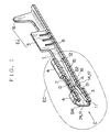
- FIG. 1 showing an exploded perspective view of a receptacle terminal 1
- a pin terminal 2 is inserted into the receptacle terminal 1 from a fore side of the receptacle terminal 1.
- the receptacle terminal 1 has a core wire connection portion 5 and an insulator crimping piece 6 in a rear side thereof.
- An arrow E shows the insertion direction of the pin terminal.
- the receptacle terminal has a top plate 7 and a bottom plate 8.
- the top plate 7 is overlaid by a fixing piece 4 and is extended laterally W from a left shoulder to a right shoulder of the receptacle terminal 1.
- a contact pressure described hereinafter is called as a surface pressure which may be produced by an area contact state, a line contact state, or a point contact state.
- the receptacle terminal 1 made of a metal material has a contact A providing a point contact state or a line contact state, contacts B1, B2 providing a point contact state or a line contact state, a resilient tongue piece 3, an accommodation chamber R, an electrical connection portion EC defined by the fixing piece 4, the core wire connection portion 5 for crimping a core wire of an electrical cable, and an electrical cable connection portion EJ having the insulation layer crimping piece 6 for crimping an insulation layer of the cable.
- the accommodation chamber R has a rectangular shape constituted by a top plate 7, a bottom plate 8, and a pair of side walls SW and provides a pin terminal entrance IN.
- the resilient tongue piece 3 has a fold 11 and a free end 12. Under the resilient tongue piece 3, there is provided a deflection restricting member 14 for the resilient tongue piece.
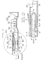
- FIG. 2 is a longitudinal sectional view showing primary parts of the present invention.
- FIG. 3 is a sectional view taken along line Y1-Y1 of FIG. 2.
- the receptacle terminal 1 of FIG. 2 has received the pin terminal 2.
- the pin terminal 2 has a tapered tip 13 which can be easily inserted into the receptacle terminal 1.
- the resilient tongue piece 3 of the receptacle terminal 1 exerts a push force Fa on the pin terminal 2 at the contact A. Due to the push force Fa, reaction forces Fb1, Fb2 are exerted on the pin terminal 2 at the contacts B1 and B2. Thereby, the pin terminal 2 gets caught by the contact A and the contacts B1, B2 of the receptacle terminal 1.
- the receptacle terminal 1 has the contact A and the contacts B1, B2 to electrically connect to the pin terminal 2.
- Each of the contacts A, B1, B2 is of a point contact type.
- the contacts A, B1, B2 catch the pin terminal 2 to electrically connect thereto, allowing a stable electrical connection thereof.
- the contacts A, B1, B2 each have an appropriately smaller contact area.
- the contact A' providing a line contact state has a higher contact pressure ⁇ a' while the contact B' has an extremely small contact pressure ⁇ b'.
- a contact pressure ⁇ a of the contacts A is not much different from a contact pressure ⁇ b1 or ⁇ b2.
- the push force Fa produced by the resilient tongue piece 3 of the receptacle terminal 1 is exerted on the contact A, and reaction forces Fb1, Fb2 are produced at the contacts B1, B2.
- reaction forces Fb1, Fb2 are produced at the contacts B1, B2.
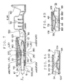
- FIG. 4 is a longitudinal sectional view showing primary parts of a second embodiment of the present invention.
- FIG. 5 is a sectional view taken along line Y2-Y2 of FIG. 4.
- a receptacle terminal 1 of FIG. 4 has received a pin terminal 2'.
- the pin terminal 2' has a tapered tip 13' which can be easily inserted into the receptacle terminal 1.
- a resilient tongue piece 3' of the receptacle terminal 1 exerts a push force Fa' on the pin terminal 2' at the contact A. Due to the push force Fa', reaction forces Fb1', Fb2' are exerted on the pin terminal 2' at the contacts B1 and B2. Thereby, the pin terminal 2' gets caught by the contact A and the contacts B1, B2 of the receptacle terminal 1.
- the receptacle terminal 1 has the contact A and the contacts B1, B2 to electrically connect to the pin terminal 2'.
- Each of the contacts A, B1, B2 is of a line contact type.
- the contacts A, B1, B2 catch the pin terminal 2' to electrically connect thereto, allowing a stable electrical connection thereof.
- the contacts A, B1, B2 each have an appropriately smaller contact area.
- the contact A' providing a line contact state has a higher contact pressure ⁇ a' while the contact B' has an extremely small contact pressure ⁇ b'.
- a contact pressure ⁇ a' of the contacts A is not much different from a contact pressure ⁇ b1' or ⁇ b2'.
- the push force Fa' produced by the resilient tongue piece 3 of the receptacle terminal 1 is exerted on the contact A, and reaction forces Fb1', Fb2' are produced at the contacts B1, B2.
- the receptacle terminal 1 can surely catch the pin terminal 2', allowing a reliable electrical connection thereof.
- the receptacle terminal 1 can receive either of the pin terminal 2 (FIGS. 2 and 3) and the pin terminal 2' (FIGS. 4 and 5).
- the push force Fa is equal to the sum of the reaction forces Fb1 and Fb2
- the push force Fa' is equal to the sum of the reaction forces Fb1' and Fb2'.
- two imaginary lines L1, L2 are provided at the contacts B1, B2.
- the imaginary lines L1, L2 are perpendicular to a general plane of the top plate 7 or the bottom plate 8 of the receptacle terminal.
- the contact A of the resilient tongue piece 3 is positioned within a distance X between the imaginary lines L1, L2.
- Such arrangement of the contacts B1, B2 and the contact A allows a balanced engagement of the pin terminal 2 or 2' with the receptacle terminal 1 for a long time.
- the contacts A, B1, B2 can catch the pin terminal 2 or 2' by the three triangular points to ensure an electrical connection of the terminals.
- the tip 13 of the pin terminal 2 may be inclined when received in the receptacle terminal. This causes an unstable electrical connection of the terminals.
- the forward end of the pin terminal would be inclined toward the bottom plate 8.
- the forward end of the pin terminal would be is inclined toward the top plate 7.
- the contacts B1 and B2 of the receptacle are defined by laterally press-forming a longitudinal middle of the terminal top plate 7 (FIGS. 3 and 5).
- the contacts B1 and B2 are disposed along an insertion direction E (FIGS. 2 and 4) of the pin terminal.
- the terminal top plate 7 has a curved portion with a gentle curvature D connecting the contact B1 to the contact B2.
- the curved portion D is located inside from a general plane including the terminal top plate 7.
- the terminal top plate 7 is easily formed with the contacts B1 and B2.
- the receptacle terminal top plate 7 can maintain its appropriate mechanical strength.
- the distance X between the two imaginary lines L1, L2, which is equal to a longitudinal distance between the contacts B1 and B2, is not smaller than a thickness Y of the pin terminal 2.
- Such determined distance X between the contacts B1 and B2 can reliably hold the pin terminal 2 in the receptacle terminal 1. On the contrary, a shorter distance between the contacts B1 and B2 would cause an unstable position of the pin terminal 2 in the receptacle terminal 1.
- the distance X (FIGS. 2 and 4) between the contacts B1, B2 is preferably limited such that the contacts B1, B2 are in no interference relation with the securing piece 4.
- the contact A is upwardly gently curved, while the contacts B1 and B2 each are a downwardly oriented projection having a gentle curvature.
- the three contacts A, B1, B2 of the receptacle terminal 1 can catch the pin terminal 2 or 2' at balanced positions.
- the contacts A, B1, B2 of the receptacle terminal 1 each have a gentle peak to cause no damage to the pin terminal 2 or 2'. Furthermore, the pin terminal 2 or 2' is supported by the contacts triangularly positioned, allowing a sure engagement of the pin terminal 2 or 2' with the receptacle terminal 1 to provide a reliable electrical connection thereof.
- the pin terminal 2 or 2' is inserted into or drawn out from the receptacle terminal 1 at assembling of an associated electric appliance connected to electrical cables or at repair of the appliance.
- the contacts A, B1, B2 each having a gentle curvature allow a smooth insertion and drawn-out of the pin terminal 2 or 2' with no undesirable interference with projections of the receptacle terminal.
- one of the contacts A, B1, B2 has an extremely steep peak, since the peak may cause a scratch on the pin terminal 2 or 2' at the insertion of the pin terminal 2 or 2' into the receptacle terminal 1.
- the curbed contacts A, B1, B2 may be easily formed by press molding when the receptacle terminal 1 is manufactured.
- FIG. 3 is a sectional view taken along line Y1-Y1 of FIG. 2 for showing a connection structure of receptacle terminal 1 and the pin terminal 2.
- the pin terminal 2 is rectangular in section. Each of four side lines 10 connecting corners 9 of the rectangle is outwardly gently swelled.
- the pin terminal 2 is inserted into and engaged with the receptacle terminal 1.
- the pin terminal 2 is substantially a square in section.
- the pin terminal 2 has the square section and each side line is outwardly swelled.
- the pin terminal 2 can be quickly inserted into the receptacle terminal 1 since any side face of the pin terminal 2 can be a contact surface for the receptacle terminal 1.
- the contact A of the resilient tongue piece 3 may be a line contact one.
- connection structure provides a smaller contact area of the receptacle terminal 1 and the pin terminal 2. This is advantageous for a reliable electrical connection of the terminals.
- the contacts A, B1, B2 each are a point contact one.
- the contact A providing a line contact state has a higher contact pressure ⁇ a' while the contact B has an extremely small contact pressure ⁇ b'.
- a contact pressure ⁇ a of the contacts A is not much different from a contact pressure ⁇ b1 or ⁇ b2.
- the receptacle terminal 1 may be provided with a guide or a holding structure for laterally positioning the pin terminal 2 of FIG. 3. These additional structures enable a more reliable engagement of the pin terminal 2 having the rectangular section with the receptacle terminal 1.
- At least one side face of the pin terminal 2 may be a flat surface, but the contacts A, B1, B2 of the receptacle terminal 1 each are defined to keep a point contact with the pin terminal 1.
- FIG. 6 is a longitudinal sectional view of a receptacle terminal 100 of a third embodiment of the present invention.
- the receptacle terminal 100 made of a metal material has a contact B10 providing a point contact state or a line contact state, contacts A10, A20 providing a point contact state or a line contact state, a resilient tongue piece 30, an accommodation chamber R10, an electrical connection portion EC10 defined by a fixing piece 40, a core wire connection portion 50 for crimping a core wire of an electrical cable, and an electrical cable connection portion EJ10 having a crimping piece 60 for crimping an insulation layer of the cable.
- the accommodation chamber R10 has a rectangular shape constituted by a top plate 70, a bottom plate 80, and a pair of side walls SW10 and provides a pin terminal entrance IN10.
- the resilient tongue piece 30 has a fold 110 and a free end 120.
- FIG. 7 is a longitudinal sectional view showing an engagement state of the receptacle terminal 100 of FIG. 6 with a pin terminal 2'.
- the pin terminal 2' has a tapered tip 13' which can be easily inserted into the receptacle terminal 100.
- the resilient tongue piece 30 of the receptacle terminal 100 exerts a push force Fb10 on the pin terminal 2' at the contact B10. Due to the push force Fb10, reaction forces Fa10, Fa20 are exerted on the pin terminal 2' at the contacts A10 and A20. Thereby, the pin terminal 2' gets caught by the contact B1 and the contacts A10, A20 of the receptacle terminal 100.
- the receptacle terminal 100 has the contact B10 and the contacts A10, A20 to electrically connect to the pin terminal 2'.
- Each of the contacts B10, A10, A20 is of a point contact type.
- the contacts B10, A10, A20 catch the pin terminal 2' to electrically connect thereto, allowing a stable electrical connection thereof.
- the contacts B10, A10, A20 each have an appropriately smaller contact area.
- the contact A' providing a line contact state has a higher contact pressure ⁇ a' while the contact B' has an extremely small contact pressure ⁇ b'.
- a contact pressure ⁇ b10 of the contacts B10 is not much different from a contact pressure ⁇ a10 or ⁇ a20.
- the push force Fb10 produced by the resilient tongue piece 30 of the receptacle terminal 100 is exerted on the contact B10, and reaction forces Fa10, Fa20 are produced at the contacts A10, A20.
- the receptacle terminal 100 can surely catch the pin terminal 2', allowing a reliable electrical connection thereof.
- the push force Fb10 is equal to the sum of the reaction forces Fa10 and Fa 20.
- two imaginary lines L10, L20 are provided at the contacts A10, A20.
- the imaginary lines L10, L20 are perpendicular to a general plane of the top plate 70 or the bottom plate 80 of the receptacle terminal.
- the contact B10 of the resilient tongue piece 30 is positioned within a distance X10 between the imaginary lines L10, L20.
- Such arrangement of the contacts A10, A20 and the contact B10 allows a balanced engagement of the pin terminal 2' with the receptacle terminal 1 for a long time.
- the contacts B10, A10, A20 can catch the pin terminal 2' by the three triangular points to ensure an electrical connection of the terminals.
- the tip 13' of the pin terminal 2' may be inclined when received in the receptacle terminal. This causes an unstable electrical connection of the terminals.
- the contact B10 is positioned in a pin terminal insertion side outside of the distance X10, the forward end of the pin terminal would be inclined toward the top plate 70.
- the contact B10 is positioned in a cable connection side outside of the distance X10, the forward end of the pin terminal would be is inclined toward the bottom 80.
- the contacts A10 and A20 of the receptacle terminal are defined by laterally press-forming a longitudinal middle portion of the terminal bottom plate 80.
- the contacts A10 and A20 are disposed along an insertion direction E of the pin terminal.
- the terminal bottom plate 80 has a curved portion with a gentle curvature D10 connecting the contact A10 to the contact A20.
- the curved portion D10 is located inside from a general plane including the terminal bottom plate 80.
- the terminal bottom plate 80 is easily formed with the contacts A10 and A20.
- the receptacle terminal bottom plate 80 can maintain its appropriate mechanical strength.
- the distance X10 between the two imaginary lines L10, L20 which is equal to a longitudinal distance between the contacts A10 and A20, is not smaller than a thickness Y of the pin terminal 2'.
- Such determined distance X10 between the contacts A10 and A20 can reliably hold the pin terminal 2' in the receptacle terminal 100. On the contrary, a shorter distance between the contacts A10 and A20 would cause an unstable position of the pin terminal 2' in the receptacle terminal 100.
- the distance X10 (FIGS. 6 and 7) between the contacts A10, A20 is preferably limited such that the contacts A10, A20 are in no interference relation with the securing piece 40.
- the contact B10 is upwardly gently curved, while the contacts A10 and A20 each are a downwardly oriented projection having a gentle curvature.
- the three contacts B10, A10, A20 of the receptacle terminal 100 can catch the pin terminal 2' at balanced positions.
- the contacts B10, A10, A20 of the receptacle terminal 100 each have a gentle peak to cause no damage to the pin terminal 2'. Furthermore, the pin terminal 2' is supported by the contacts triangularly positioned, allowing a sure engagement of the pin terminal 2' with the receptacle terminal 100 to provide a reliable electrical connection thereof.
- the pin terminal 2' is inserted into or drawn out from the receptacle terminal 1 at assembling of an associated electric appliance connected to electrical cables or at repair of the appliance.
- the contacts B10, A10, A20 each having a gentle curvature allow a smooth insertion and drawn-out of the pin terminal 2' with no undesirable interference with projections of the receptacle terminal.
- one of the contacts B10, A10, A20 has an extremely steep peak, since the peak may cause a scratch on the pin terminal 2' at the insertion of the pin terminal 2' into the receptacle terminal 100.
- the curbed contacts B10, A10, A20 may be easily formed by press molding when the receptacle terminal 100 is manufactured.
- FIGS. 8A to 8D each are a longitudinal sectional view for showing primary parts of another embodiment of the present invention to illustrate an electrical contact state of one of receptacle terminals 1A to 1D.
- a receptacle terminal 1A has a bottom plate 8A on which a resilient contact piece 3A is disposed.
- the resilient contact piece 3A has each free end 12A or 12A' to define a spring supported at each end thereof.
- the receptacle terminal 1A consists of the two parts.
- the resilient contact piece 3A is provided with two contacts AA1 and AA2.
- the receptacle terminal 1A has a top plate 7A having an inner surface provided with a protrusion contact BA.
- a receptacle terminal 1B has a bottom plate 8B having an inner surface provided with a protrusion contact AB.
- the receptacle terminal 1B has a top plate 7B from which a resilient contact tongue 3B is extended through a fold 11B to have free end 12B.
- the resilient contact tongue 3B is formed with a pair of contacts BB1 and BB2.
- the top plate 7B is overlaid by a securing piece 4B.
- a receptacle terminal 1C has a top plate 7c having an inner surface provided with a protrusion contact BC.
- the receptacle terminal 1C has a bottom plate 8C from which a resilient contact tongue 3C is extended through a fold 11C to have free end 12C.
- the resilient contact tongue 3C is formed with a pair of contacts AC1 and AC2.
- a receptacle terminal 1D has two opposed resilient contact tongues 3D and 3D'.
- the receptacle terminal 1D has a bottom plate 8D from which one resilient contact tongue 3D is extended through a fold 11D to have free end 12D.
- the resilient contact tongue 3D is formed with a pair of contacts AD1 and AD2.
- the receptacle terminal 1D has atop plate 7D from which the other resilient contact tongue 3D' is extended through a fold 11D' to have free end 12D'.
- the resilient contact tongue 3D' is formed with a contact BD.
- the contacts formed on the receptacle terminals and pin terminals discussed above may be a line contact one or a point contact one fit for an application of the terminals.
- FIG. 9 illustrates a basic pattern of three-point contact, a first variation, and a second variation.
- the first variation has contact points deviated from the basic pattern.
- the second variation is provided with a curved pin terminal. Note that the basic pattern of three-point contact may be arranged upside down.
- the three-point contact discussed of the present invention allows the receptacle terminal to reliably catch the pin terminal even when the contact points are deviated from the basic pattern like the first assumed pattern or when a bent pin terminal is provided like the second assumed pattern.
- the pin terminal 2 of FIG. 3 may be modified to have only two swelled side faces engaged with the top plate 7 and the bottom plate 8 of the receptacle terminal 1.
- the contacts A, B1, B2 of the receptacle terminal 1 each may be a projection having a point peak.
- the pin terminal may have four flat side faces, for example, as illustrated in FIG. 5. Thereby, the contacts A, B1, B2 each can keep a point contact state with the pin terminal 2.
- the corner 9 or 9' of the pin terminal 2 or 2' is rounded as illustrated in FIG. 3 or 5. A sharp edge of the corner 9 or 9' is undesired to prevent possible injury of fingers or a damage of an inside structure of the receptacle terminal 1.
- the gentle curvature discussed of the present invention may be one which causes no crack in a metal plate of the receptacle terminal 1 when the receptacle terminal is formed.
- the curvature is determined in consideration of the material and thickness of the metal plate.
- the contacts A, B1, B2 discussed of the present invention may be point contact ones or line contact ones as far as the contacts guarantee a correct electrical connection.
- each of the contacts A, B1, B2 may be a projection having a point peak or may be a wave-shaped one having a peak line. Because, such configured contacts each have a small contact area to achieve the present invention.
- the pin terminal 2 or 2' may be of a tab-shaped type, a round pin type, or another pin type which is used in a print circuit board. However, the present invention is best applied to the pin terminal 2 or 2' having a generally rectangular section and the receptacle terminal 1 having a substantially box-shaped section as illustrated in FIGS. 1 to 3.
- pin terminal 2 or 2' and the receptacle terminal 1 related to the present invention may not be surface-treated or may be surface-treated by a gold galvanization against corrosion.
- the receptacle terminal 1 and the pin terminal 2 or 2' of the present invention may be made of an electrically conductive metal such as a bronze, another copper alloy, or an aluminum alloy.
- the receptacle terminal 1 is defined to have the resilient tongue piece 3, the securing piece 4, the contacts A, B1, B2, the core wire connection portion 5, the insulation layer crimping piece 6, and the deflection restricting member 14.
- a material constituting the receptacle terminal 1 should be advantageous for stamping, bending, and plastic molding thereof.
- the material should have a resiliency to form the resilient tongue piece 3 and an anticorrosion performance against moisture, and the material should not be expensive in view of a mass production of the terminals.
Landscapes
- Coupling Device And Connection With Printed Circuit (AREA)
- Details Of Connecting Devices For Male And Female Coupling (AREA)
Abstract
Description
Claims (7)
- A receptacle terminal comprising:a plurality of first contacts disposed in parallel with each other on an inner surface of a first plate of the receptacle terminal and arranged in an insertion direction of an associated pin terminal anda resilient tongue piece opposed to the first plate and having at least one second contact,wherein the second contact of the resilient tongue piece is positioned between the first contacts.
- A receptacle terminal electrically connected to an associated pin terminal, the receptacle terminal comprising a plurality of first contacts electrically connected to the pin terminal, wherein the receptacle terminal can catch the pin terminal with all the first contacts being electrically connected to the pin terminal.
- A connection structure of a receptacle terminal with a pin terminal comprising a plurality of first contacts formed on the receptacle terminal for electrical connection with the pin terminal,
wherein at least one of the contacts can electrically connect to the pin terminal when the pin terminal has been inserted in the receptacle terminal, and the pin terminal is rectangular in its lateral section, the pin terminal having at least one outer curved surface gently outwardly swelled for connection to the pin terminal. - The connection structure as claimed in claim 3 or the receptacle terminal as claimed in claim 2,
wherein the first contacts are disposed in parallel with each other on an inner surface of a first plate of the receptacle terminal and arranged in an insertion direction of the pin terminal, and the receptacle terminal further comprises a resilient tongue piece opposed to the first plate and having at least one second contact, the second contact of the resilient tongue piece positioned between the first contacts. - The connection structure as claimed in claim 4 or the receptacle terminal as claimed in claim 1 or 4, wherein the second contact of the resilient tongue piece is positioned between the first contacts in a longitudinal direction of the receptacle terminal.
- The connection structure as claimed in claim 4 or the receptacle terminal as claimed in claim 1 or 4,
wherein the first contacts of the receptacle terminal each are located substantially at the middle of the first plate of the receptacle terminal in a lateral direction of the receptacle terminal. - The connection structure as claimed in claim 4 or the receptacle terminal as claimed in claim 1 or 4,
wherein the first plate of the receptacle terminal has a gentle curvature portion connecting the first contacts in a longitudinal direction of the receptacle terminal, and the gentle curvature portion is located inside from a general surface of the first plate. .
Applications Claiming Priority (4)
| Application Number | Priority Date | Filing Date | Title |
|---|---|---|---|
| JP2000171134 | 2000-06-07 | ||
| JP2000171134 | 2000-06-07 | ||
| JP2001167105 | 2001-06-01 | ||
| JP2001167105A JP2002063961A (en) | 2000-06-07 | 2001-06-01 | Female terminal and connection structure between female terminal and male terminal |
Publications (3)
| Publication Number | Publication Date |
|---|---|
| EP1172893A2 true EP1172893A2 (en) | 2002-01-16 |
| EP1172893A3 EP1172893A3 (en) | 2002-11-27 |
| EP1172893B1 EP1172893B1 (en) | 2008-04-09 |
Family
ID=26593512
Family Applications (1)
| Application Number | Title | Priority Date | Filing Date |
|---|---|---|---|
| EP01113943A Expired - Lifetime EP1172893B1 (en) | 2000-06-07 | 2001-06-07 | Electrical receptacle terminal and connection structure thereof with pin terminal |
Country Status (5)
| Country | Link |
|---|---|
| US (1) | US6547608B2 (en) |
| EP (1) | EP1172893B1 (en) |
| JP (1) | JP2002063961A (en) |
| CN (1) | CN1279657C (en) |
| DE (1) | DE60133514T2 (en) |
Cited By (1)
| Publication number | Priority date | Publication date | Assignee | Title |
|---|---|---|---|---|
| DE102006027674B3 (en) * | 2006-06-14 | 2008-01-31 | Tyco Electronics Amp Gmbh | Electrical bushing contact, has two contact points, which are provided at upper contact element, at spring-shackles contact element, and at lower contact element |
Families Citing this family (99)
| Publication number | Priority date | Publication date | Assignee | Title |
|---|---|---|---|---|
| JP2003338334A (en) * | 2002-05-20 | 2003-11-28 | Yazaki Corp | Female terminal, its connection structure, and wire harness |
| DE10247410B4 (en) * | 2002-10-11 | 2014-02-13 | Robert Bosch Gmbh | contact element |
| JP3984539B2 (en) * | 2002-12-17 | 2007-10-03 | 株式会社オートネットワーク技術研究所 | Connector terminal and manufacturing method thereof |
| JP2004253166A (en) * | 2003-02-18 | 2004-09-09 | Yazaki Corp | Female terminal |
| JP4498721B2 (en) * | 2003-11-05 | 2010-07-07 | 株式会社オートネットワーク技術研究所 | Connector manufacturing method |
| JP3976008B2 (en) * | 2004-01-07 | 2007-09-12 | 住友電装株式会社 | Terminal fitting |
| JP4259472B2 (en) * | 2005-02-02 | 2009-04-30 | 住友電装株式会社 | Terminal fitting |
| KR101121255B1 (en) * | 2005-02-09 | 2012-03-23 | 에프씨아이 오토모티브 홀딩 | Female electrical contact comprising spring contact plates |
| DE102006009035A1 (en) | 2005-02-28 | 2006-09-07 | Yazaki Corp. | A method of making a metal clip and metal clip made by the method |
| EP1720219A1 (en) * | 2005-05-03 | 2006-11-08 | Delphi Technologies, Inc. | Electrical connection element |
| US7387550B2 (en) * | 2005-07-21 | 2008-06-17 | Tyco Electronics Corporation | Dual beam receptacle contact |
| US7537497B2 (en) * | 2005-09-26 | 2009-05-26 | Fci Americas Technology, Inc. | Multi-piece electrical receptacle terminal |
| JP4722707B2 (en) * | 2005-10-13 | 2011-07-13 | 日本圧着端子製造株式会社 | Vertical mating female terminal and housing to which this is mounted |
| JP2007141509A (en) * | 2005-11-15 | 2007-06-07 | Sumitomo Wiring Syst Ltd | Terminal fitting |
| EP1786066B1 (en) * | 2005-11-15 | 2011-01-26 | Sumitomo Wiring Systems, Ltd. | A connector |
| JP4482823B2 (en) * | 2005-12-26 | 2010-06-16 | 住友電装株式会社 | Terminal fitting |
| JP2006128143A (en) * | 2006-02-06 | 2006-05-18 | Sumitomo Wiring Syst Ltd | Male side terminal fitting |
| JP4710797B2 (en) * | 2006-11-01 | 2011-06-29 | 住友電装株式会社 | Terminal fitting |
| JP4858293B2 (en) * | 2007-05-08 | 2012-01-18 | 住友電装株式会社 | Female terminal bracket |
| US7503813B1 (en) | 2007-05-17 | 2009-03-17 | Yazaki North America, Inc. | Electrical terminal with contoured contact element |
| DE102007044412A1 (en) * | 2007-09-18 | 2009-03-19 | Lear Corp., Southfield | Electrical connector assembly |
| US7595715B2 (en) * | 2007-09-27 | 2009-09-29 | Lear Corporation | High power case fuse |
| DE102007049055B3 (en) * | 2007-10-11 | 2009-03-26 | Tyco Electronics Amp Gmbh | Vibration damping contact element |
| US8104173B2 (en) * | 2008-04-08 | 2012-01-31 | Delphi Technologies, Inc. | Method for manufacturing a series of electric terminals |
| US8021200B2 (en) * | 2008-08-04 | 2011-09-20 | Tyco Electronics Corporation | Socket contact |
| US20100029146A1 (en) * | 2008-08-04 | 2010-02-04 | Tyco Electronics Corporation | Socket contact |
| KR101598633B1 (en) * | 2009-11-11 | 2016-02-29 | 타이코에이엠피 주식회사 | Terminal for connector |
| JP5480612B2 (en) * | 2009-12-17 | 2014-04-23 | 矢崎総業株式会社 | Terminal for fuse |
| JP2011181330A (en) * | 2010-03-01 | 2011-09-15 | Sumitomo Wiring Syst Ltd | Terminal fitting |
| CN102834981B (en) * | 2010-03-31 | 2015-06-24 | 古河电气工业株式会社 | Female terminal |
| JP2012079505A (en) | 2010-09-30 | 2012-04-19 | Japan Aviation Electronics Industry Ltd | Connector assembly |
| US8333622B2 (en) * | 2010-12-06 | 2012-12-18 | Delphi Technologies, Inc. | Dual contact beam terminal |
| JP5634255B2 (en) * | 2010-12-24 | 2014-12-03 | 日本航空電子工業株式会社 | Contact, contact manufacturing method, electrical connector |
| CN102790308B (en) * | 2011-05-20 | 2015-08-12 | 泰科电子(上海)有限公司 | Electric connector terminal |
| US8911253B2 (en) * | 2011-06-13 | 2014-12-16 | Tyco Electronics Corporation | Receptacle contact |
| JP5723694B2 (en) * | 2011-06-21 | 2015-05-27 | 矢崎総業株式会社 | Female terminal |
| JP5433653B2 (en) | 2011-08-31 | 2014-03-05 | 日本航空電子工業株式会社 | connector |
| JP2013069496A (en) * | 2011-09-21 | 2013-04-18 | Sumitomo Wiring Syst Ltd | Terminal fitting |
| KR101275285B1 (en) * | 2011-09-23 | 2013-06-17 | 한국단자공업 주식회사 | Receptacle terminal |
| WO2013065583A1 (en) * | 2011-11-02 | 2013-05-10 | 住友電気工業株式会社 | Aluminum alloy sheet for terminal, terminal fitting, and electric wire terminal connection structure |
| JP2013098088A (en) | 2011-11-02 | 2013-05-20 | Sumitomo Wiring Syst Ltd | Female type terminal fitting |
| JP2013118102A (en) * | 2011-12-02 | 2013-06-13 | Yazaki Corp | Female terminal structure |
| US8974256B2 (en) * | 2012-04-26 | 2015-03-10 | Sumitomo Wiring Systems, Ltd. | Terminal fitting and production method therefor |
| JP5803798B2 (en) * | 2012-04-26 | 2015-11-04 | 住友電装株式会社 | Terminal fitting |
| JP5521124B1 (en) * | 2012-08-07 | 2014-06-11 | 古河電気工業株式会社 | Crimp terminal, connection structure, connector, wire harness, method for producing crimp terminal, method for producing connection structure |
| JP2014049375A (en) * | 2012-09-03 | 2014-03-17 | Yazaki Corp | Connection terminal |
| JP6124537B2 (en) * | 2012-09-03 | 2017-05-10 | 矢崎総業株式会社 | Female terminal |
| JP2014160545A (en) * | 2013-02-19 | 2014-09-04 | Sumitomo Wiring Syst Ltd | Female terminal metal fitting |
| JP2014170709A (en) * | 2013-03-05 | 2014-09-18 | Sumitomo Wiring Syst Ltd | Female terminal fitting |
| KR101446536B1 (en) | 2013-03-19 | 2014-11-03 | 주식회사 유라코퍼레이션 | Female Terminal |
| EP3005485B1 (en) | 2013-06-07 | 2018-01-03 | FCI Asia Pte. Ltd. | Cable connector |
| US9972932B2 (en) * | 2013-08-19 | 2018-05-15 | Fci Americas Technology Llc | Electrical connector with high retention force |
| JP2015050131A (en) * | 2013-09-04 | 2015-03-16 | 矢崎総業株式会社 | Female terminal |
| JP6086244B2 (en) * | 2013-11-19 | 2017-03-01 | 住友電装株式会社 | Multi-contact terminal |
| US10230189B2 (en) | 2013-12-03 | 2019-03-12 | Amphenol Fci Asia Pte Ltd | Connector and pin receiving contact for such a connector |
| CN203707415U (en) | 2014-01-26 | 2014-07-09 | 上海莫仕连接器有限公司 | terminal |
| JP2015153688A (en) * | 2014-02-18 | 2015-08-24 | 矢崎総業株式会社 | Connecting terminal |
| WO2015125682A1 (en) | 2014-02-18 | 2015-08-27 | 矢崎総業株式会社 | Connection terminal |
| JP2015204186A (en) * | 2014-04-14 | 2015-11-16 | 矢崎総業株式会社 | terminal |
| JP6359861B2 (en) * | 2014-04-16 | 2018-07-18 | 矢崎総業株式会社 | Terminal |
| JP6269309B2 (en) | 2014-05-14 | 2018-01-31 | 住友電装株式会社 | Female terminal |
| JP6276113B2 (en) * | 2014-06-02 | 2018-02-07 | ホシデン株式会社 | connector |
| JP2016024902A (en) * | 2014-07-17 | 2016-02-08 | 矢崎総業株式会社 | Female electrical contact part and formation method of female electrical contact part |
| KR20170036691A (en) * | 2014-07-31 | 2017-04-03 | 다부치 덴키 가부시키가이샤 | Method for joining terminal and electric wire and electric wire connection terminal |
| JP5794363B1 (en) * | 2014-09-02 | 2015-10-14 | 第一精工株式会社 | Connector terminal |
| JP5862755B1 (en) * | 2014-12-12 | 2016-02-16 | 第一精工株式会社 | Connector terminal |
| US9673549B2 (en) * | 2014-12-17 | 2017-06-06 | Toyota Jidosha Kabushiki Kaisha | Connector with movement suppression function during excessive vibration |
| JP6487261B2 (en) * | 2015-04-13 | 2019-03-20 | 矢崎総業株式会社 | Female terminal |
| JP2016219097A (en) * | 2015-05-14 | 2016-12-22 | 矢崎総業株式会社 | Contact connection structure |
| JP6154430B2 (en) * | 2015-06-02 | 2017-06-28 | 矢崎総業株式会社 | Female terminal fitting and connector having the same |
| JP2017010703A (en) * | 2015-06-19 | 2017-01-12 | 矢崎総業株式会社 | Terminal and terminal connection structure |
| JP6299703B2 (en) * | 2015-08-05 | 2018-03-28 | 住友電装株式会社 | Female terminal |
| JP6615574B2 (en) * | 2015-10-28 | 2019-12-04 | 矢崎総業株式会社 | Terminal fitting and manufacturing method |
| EP3211722B1 (en) * | 2016-02-23 | 2020-04-22 | TE Connectivity Germany GmbH | Contact stud and contact assembly in particular for car technology |
| JP2017157415A (en) * | 2016-03-02 | 2017-09-07 | 矢崎総業株式会社 | Connection terminal |
| EP3240114B1 (en) * | 2016-04-25 | 2019-01-23 | Aptiv Technologies Limited | Electrical contact terminal and method to manufacture the same |
| JP6085709B2 (en) * | 2016-04-28 | 2017-02-22 | 矢崎総業株式会社 | Female terminal structure |
| JP6607141B2 (en) | 2016-05-12 | 2019-11-20 | 住友電装株式会社 | Terminal |
| JP2017204396A (en) * | 2016-05-12 | 2017-11-16 | 住友電装株式会社 | Terminal |
| DE102016110231A1 (en) * | 2016-06-02 | 2017-12-07 | Te Connectivity Germany Gmbh | Contact element and contact system |
| JP2018010818A (en) * | 2016-07-15 | 2018-01-18 | 住友電装株式会社 | Terminal structure |
| JP6776050B2 (en) | 2016-08-01 | 2020-10-28 | 日本航空電子工業株式会社 | Female terminal and connector with it |
| JP6807024B2 (en) * | 2017-04-14 | 2021-01-06 | 株式会社オートネットワーク技術研究所 | Female terminal |
| JP2019057423A (en) * | 2017-09-21 | 2019-04-11 | 日本航空電子工業株式会社 | Female terminals and connectors |
| CN115986449A (en) | 2018-03-16 | 2023-04-18 | 富加宜(美国)有限责任公司 | High density electrical connector |
| US10290965B1 (en) * | 2018-04-05 | 2019-05-14 | Delphi Technologies, Llc | Self-gapping electrical-terminal |
| CN108539470B (en) * | 2018-04-18 | 2019-10-25 | 宁波晨翔电子有限公司 | A kind of row's female connectors |
| JP2020042914A (en) * | 2018-09-06 | 2020-03-19 | 矢崎総業株式会社 | Terminal fitting |
| JP7052665B2 (en) * | 2018-10-02 | 2022-04-12 | 株式会社オートネットワーク技術研究所 | Female terminal |
| DE102019207983A1 (en) * | 2019-05-31 | 2020-12-03 | Robert Bosch Gmbh | Device for reducing mechanical loads under and in a functional component |
| CN110289516A (en) * | 2019-07-29 | 2019-09-27 | 河南天海电器有限公司 | A multi-contact sealed socket terminal |
| CN110444933A (en) * | 2019-08-30 | 2019-11-12 | 厦门广泓工贸有限公司 | A kind of patch electric connector |
| JP7298461B2 (en) * | 2019-12-05 | 2023-06-27 | 住友電装株式会社 | Female terminals and female connectors |
| DE102020202034A1 (en) | 2020-02-18 | 2021-08-19 | Robert Bosch Gesellschaft mit beschränkter Haftung | Vertical field effect transistor, method for producing the same and component comprising vertical field effect transistors |
| JP7435329B2 (en) * | 2020-07-14 | 2024-02-21 | 住友電装株式会社 | terminal fittings |
| JP7168626B2 (en) * | 2020-10-23 | 2022-11-09 | 矢崎総業株式会社 | Connecting terminal |
| JP7620446B2 (en) * | 2021-02-19 | 2025-01-23 | 矢崎総業株式会社 | Connection structure between female and male terminals |
| JP7826021B2 (en) * | 2022-01-20 | 2026-03-09 | TE Connectivity Japan合同会社 | Female Terminals and Connectors |
| DE102023202447A1 (en) | 2023-03-20 | 2024-09-26 | Robert Bosch Gesellschaft mit beschränkter Haftung | Method for heating an exhaust system |
Family Cites Families (47)
| Publication number | Priority date | Publication date | Assignee | Title |
|---|---|---|---|---|
| US3836947A (en) * | 1973-02-23 | 1974-09-17 | Amp Inc | Electrical contact receptacle with helper spring |
| FR2435832A1 (en) | 1978-07-21 | 1980-04-04 | Alsthom Cgee | ELECTRICAL CONNECTION DEVICE |
| JPS5664677U (en) * | 1979-10-23 | 1981-05-30 | ||
| US4560231A (en) * | 1983-03-10 | 1985-12-24 | Elco International K.K. | Electrical connector |
| FR2559624B1 (en) * | 1984-02-14 | 1986-05-23 | Labinal | ELECTRIC CONTACT MEMBER |
| JPH0222938Y2 (en) * | 1984-11-12 | 1990-06-21 | ||
| JPS6228370U (en) * | 1985-08-02 | 1987-02-20 | ||
| JPH0332047Y2 (en) * | 1986-01-29 | 1991-07-08 | ||
| JPH0422550Y2 (en) * | 1987-02-09 | 1992-05-22 | ||
| US4919628A (en) * | 1987-10-19 | 1990-04-24 | Interlock Corporation | Tab receptacle with fixed beam contacts |
| JPH01155672U (en) * | 1988-04-19 | 1989-10-25 | ||
| JPH0299578U (en) * | 1989-01-26 | 1990-08-08 | ||
| GB2235596A (en) * | 1989-08-23 | 1991-03-06 | Itt Ind Ltd | Improvements relating to electrical connectors |
| JPH03101861U (en) * | 1990-02-01 | 1991-10-23 | ||
| JPH03126370U (en) * | 1990-04-05 | 1991-12-19 | ||
| JPH0461775A (en) | 1990-06-28 | 1992-02-27 | Fujitsu Ltd | Ic socket |
| JPH0741100Y2 (en) * | 1990-10-01 | 1995-09-20 | 日本航空電子工業株式会社 | Socket contact |
| JP2563154Y2 (en) * | 1990-10-30 | 1998-02-18 | 株式会社カンセイ | Electrical connector |
| FR2680284B1 (en) * | 1991-08-09 | 1993-12-03 | Thomson Csf | VERY LOW PIT CONNECTION DEVICE AND MANUFACTURING METHOD. |
| JPH06111871A (en) | 1992-09-30 | 1994-04-22 | Matsushita Electric Works Ltd | Connector |
| DE69424527T2 (en) * | 1993-10-01 | 2000-09-14 | Ryosei Electro Circuit Sys Ltd | CONNECTING TERMINAL AND METHOD FOR THEIR PRODUCTION |
| FR2711853B1 (en) * | 1993-10-26 | 1995-12-01 | Cinch Connecteurs Sa | Female electrical contact member. |
| WO1995019650A1 (en) * | 1994-01-12 | 1995-07-20 | Berg Technology, Inc. | Improved contact element for an electrical connector |
| JPH08213086A (en) * | 1995-02-03 | 1996-08-20 | Japan Aviation Electron Ind Ltd | Socket contact |
| JP2928987B2 (en) * | 1995-03-31 | 1999-08-03 | 日本航空電子工業株式会社 | Contact and manufacturing method thereof |
| US5791945A (en) * | 1995-04-13 | 1998-08-11 | The Whitaker Corporation | High force contact |
| US5681190A (en) * | 1995-05-23 | 1997-10-28 | Cardell Corporation | Torsional blade receptacle |
| JP3497615B2 (en) * | 1995-07-12 | 2004-02-16 | 矢崎総業株式会社 | Female terminal |
| JPH0935796A (en) * | 1995-07-24 | 1997-02-07 | Yazaki Corp | Female terminal |
| US5800220A (en) * | 1995-10-23 | 1998-09-01 | Framatome Connectors Interlock Inc. | Tab receptacle terminal |
| EP0795930B1 (en) * | 1996-03-11 | 2002-07-17 | Molex Incorporated | High contact force pin-receiving electrical contact |
| FR2749442B1 (en) * | 1996-06-03 | 1998-07-10 | Framatome Connectors Int | FEMALE ELECTRIC CONTACT TERMINAL WITH REINFORCED STRUCTURE |
| FR2749441B1 (en) * | 1996-06-03 | 1998-07-10 | Framatome Connectors Int | FEMALE ELECTRIC CONTACT TERMINAL WITH CONTROLLED CONTACT PRESSURE |
| US6062918A (en) * | 1996-07-01 | 2000-05-16 | The Whitaker Corporation | Electrical receptacle contact assembly |
| JP4071311B2 (en) * | 1996-12-20 | 2008-04-02 | 株式会社オートネットワーク技術研究所 | Female terminal structure |
| DE19705509C2 (en) * | 1997-02-13 | 1999-04-29 | Siemens Ag | One-piece contact spring |
| JP3379747B2 (en) * | 1997-05-20 | 2003-02-24 | 矢崎総業株式会社 | Low insertion force terminal |
| US6042433A (en) * | 1997-05-29 | 2000-03-28 | The Whitaker Corporation | Electrical contact |
| JP3807646B2 (en) * | 1997-10-31 | 2006-08-09 | 矢崎総業株式会社 | Terminal sag prevention structure |
| JPH11214058A (en) * | 1998-01-29 | 1999-08-06 | Yazaki Corp | Female terminal |
| JP3388170B2 (en) * | 1998-02-13 | 2003-03-17 | 住友電装株式会社 | Female terminal fitting |
| JPH11233191A (en) | 1998-02-16 | 1999-08-27 | Sumitomo Wiring Syst Ltd | Waterproof structure of connector |
| JP3433670B2 (en) * | 1998-05-22 | 2003-08-04 | 住友電装株式会社 | Female terminal fitting |
| JP3444398B2 (en) * | 1998-06-26 | 2003-09-08 | 住友電装株式会社 | Terminal fitting connection structure and male terminal fittings |
| JP3480693B2 (en) * | 1999-03-16 | 2003-12-22 | 住友電装株式会社 | Female terminal fitting |
| US6305993B1 (en) * | 2000-01-31 | 2001-10-23 | Tyco Electronics Amp Gmbh | Contact socket |
| JP2001250623A (en) * | 2000-03-03 | 2001-09-14 | Auto Network Gijutsu Kenkyusho:Kk | Terminal structure |
-
2001
- 2001-06-01 JP JP2001167105A patent/JP2002063961A/en active Pending
- 2001-06-06 US US09/874,054 patent/US6547608B2/en not_active Expired - Lifetime
- 2001-06-07 DE DE60133514T patent/DE60133514T2/en not_active Expired - Lifetime
- 2001-06-07 CN CNB011214511A patent/CN1279657C/en not_active Expired - Fee Related
- 2001-06-07 EP EP01113943A patent/EP1172893B1/en not_active Expired - Lifetime
Cited By (1)
| Publication number | Priority date | Publication date | Assignee | Title |
|---|---|---|---|---|
| DE102006027674B3 (en) * | 2006-06-14 | 2008-01-31 | Tyco Electronics Amp Gmbh | Electrical bushing contact, has two contact points, which are provided at upper contact element, at spring-shackles contact element, and at lower contact element |
Also Published As
| Publication number | Publication date |
|---|---|
| US6547608B2 (en) | 2003-04-15 |
| DE60133514T2 (en) | 2009-06-10 |
| CN1328361A (en) | 2001-12-26 |
| DE60133514D1 (en) | 2008-05-21 |
| EP1172893A3 (en) | 2002-11-27 |
| CN1279657C (en) | 2006-10-11 |
| JP2002063961A (en) | 2002-02-28 |
| US20010051472A1 (en) | 2001-12-13 |
| EP1172893B1 (en) | 2008-04-09 |
Similar Documents
| Publication | Publication Date | Title |
|---|---|---|
| EP1172893B1 (en) | Electrical receptacle terminal and connection structure thereof with pin terminal | |
| US6475040B1 (en) | Electrical contact receptacle to mate with round and rectangular pins | |
| EP1128474B1 (en) | Flat circuit member connector | |
| EP2876743B1 (en) | Connector between cable and substrate | |
| US4838816A (en) | Electrical terminal having a receptacle contact section of low insertion force | |
| US20050153605A1 (en) | Connection terminal | |
| US20010024913A1 (en) | Electrical contact | |
| US7878843B2 (en) | Cable assembly having hold-down arrangement | |
| EP0966062B1 (en) | IDC Socket contact with high retention force | |
| US6010377A (en) | High contact force pin-receiving electrical terminal | |
| JPH0415594B2 (en) | ||
| US5209680A (en) | Male electrical terminal with anti-overstress means | |
| US6626701B2 (en) | Connector | |
| CN110534969A (en) | Electrical connector and connector combination with the electrical connector | |
| US6843688B2 (en) | Connector in which movement of contact portion of contact is guided by insulator | |
| CN108155503A (en) | Has the electrical connector of disconnecting prevention structure | |
| US6402575B1 (en) | Tab of terminal fitting | |
| US6629864B2 (en) | Electrical contact for plug-in connector | |
| US7201606B2 (en) | Wire connection structure and connector | |
| JP2019185875A (en) | Connector device having terminal pressing structure | |
| JPH02189869A (en) | Electric connector | |
| JP4386676B2 (en) | connector | |
| JPH08250172A (en) | Receptacle type terminal | |
| EP1049207A2 (en) | Cable connector with engagement mechanism for an electrical terminal member | |
| JP3371248B2 (en) | Socket connector and small board connection structure |
Legal Events
| Date | Code | Title | Description |
|---|---|---|---|
| PUAI | Public reference made under article 153(3) epc to a published international application that has entered the european phase |
Free format text: ORIGINAL CODE: 0009012 |
|
| AK | Designated contracting states |
Kind code of ref document: A2 Designated state(s): AT BE CH CY DE DK ES FI FR GB GR IE IT LI LU MC NL PT SE TR |
|
| AX | Request for extension of the european patent |
Free format text: AL;LT;LV;MK;RO;SI |
|
| PUAL | Search report despatched |
Free format text: ORIGINAL CODE: 0009013 |
|
| AK | Designated contracting states |
Kind code of ref document: A3 Designated state(s): AT BE CH CY DE DK ES FI FR GB GR IE IT LI LU MC NL PT SE TR |
|
| AX | Request for extension of the european patent |
Free format text: AL;LT;LV;MK;RO;SI |
|
| 17P | Request for examination filed |
Effective date: 20030527 |
|
| AKX | Designation fees paid |
Designated state(s): DE FR GB SE |
|
| 17Q | First examination report despatched |
Effective date: 20030730 |
|
| 17Q | First examination report despatched |
Effective date: 20030730 |
|
| RAP1 | Party data changed (applicant data changed or rights of an application transferred) |
Owner name: YAZAKI CORPORATION |
|
| GRAP | Despatch of communication of intention to grant a patent |
Free format text: ORIGINAL CODE: EPIDOSNIGR1 |
|
| GRAS | Grant fee paid |
Free format text: ORIGINAL CODE: EPIDOSNIGR3 |
|
| GRAA | (expected) grant |
Free format text: ORIGINAL CODE: 0009210 |
|
| AK | Designated contracting states |
Kind code of ref document: B1 Designated state(s): DE FR GB SE |
|
| REG | Reference to a national code |
Ref country code: GB Ref legal event code: FG4D |
|
| REF | Corresponds to: |
Ref document number: 60133514 Country of ref document: DE Date of ref document: 20080521 Kind code of ref document: P |
|
| REG | Reference to a national code |
Ref country code: SE Ref legal event code: TRGR |
|
| ET | Fr: translation filed | ||
| PLBE | No opposition filed within time limit |
Free format text: ORIGINAL CODE: 0009261 |
|
| STAA | Information on the status of an ep patent application or granted ep patent |
Free format text: STATUS: NO OPPOSITION FILED WITHIN TIME LIMIT |
|
| 26N | No opposition filed |
Effective date: 20090112 |
|
| REG | Reference to a national code |
Ref country code: FR Ref legal event code: PLFP Year of fee payment: 16 |
|
| PGFP | Annual fee paid to national office [announced via postgrant information from national office to epo] |
Ref country code: SE Payment date: 20160613 Year of fee payment: 16 |
|
| REG | Reference to a national code |
Ref country code: FR Ref legal event code: PLFP Year of fee payment: 17 |
|
| REG | Reference to a national code |
Ref country code: SE Ref legal event code: EUG |
|
| PG25 | Lapsed in a contracting state [announced via postgrant information from national office to epo] |
Ref country code: SE Free format text: LAPSE BECAUSE OF NON-PAYMENT OF DUE FEES Effective date: 20170608 |
|
| REG | Reference to a national code |
Ref country code: FR Ref legal event code: PLFP Year of fee payment: 18 |
|
| PGFP | Annual fee paid to national office [announced via postgrant information from national office to epo] |
Ref country code: DE Payment date: 20190528 Year of fee payment: 19 |
|
| PGFP | Annual fee paid to national office [announced via postgrant information from national office to epo] |
Ref country code: FR Payment date: 20190510 Year of fee payment: 19 |
|
| PGFP | Annual fee paid to national office [announced via postgrant information from national office to epo] |
Ref country code: GB Payment date: 20190605 Year of fee payment: 19 |
|
| REG | Reference to a national code |
Ref country code: DE Ref legal event code: R119 Ref document number: 60133514 Country of ref document: DE |
|
| GBPC | Gb: european patent ceased through non-payment of renewal fee |
Effective date: 20200607 |
|
| PG25 | Lapsed in a contracting state [announced via postgrant information from national office to epo] |
Ref country code: FR Free format text: LAPSE BECAUSE OF NON-PAYMENT OF DUE FEES Effective date: 20200630 Ref country code: GB Free format text: LAPSE BECAUSE OF NON-PAYMENT OF DUE FEES Effective date: 20200607 |
|
| PG25 | Lapsed in a contracting state [announced via postgrant information from national office to epo] |
Ref country code: DE Free format text: LAPSE BECAUSE OF NON-PAYMENT OF DUE FEES Effective date: 20210101 |