JP2004253166A - Female terminal - Google Patents
Female terminal Download PDFInfo
- Publication number
- JP2004253166A JP2004253166A JP2003039687A JP2003039687A JP2004253166A JP 2004253166 A JP2004253166 A JP 2004253166A JP 2003039687 A JP2003039687 A JP 2003039687A JP 2003039687 A JP2003039687 A JP 2003039687A JP 2004253166 A JP2004253166 A JP 2004253166A
- Authority
- JP
- Japan
- Prior art keywords
- bottom wall
- contact piece
- elastic contact
- terminal
- male terminal
- Prior art date
- Legal status (The legal status is an assumption and is not a legal conclusion. Google has not performed a legal analysis and makes no representation as to the accuracy of the status listed.)
- Pending
Links
Images


Classifications
-
- H—ELECTRICITY
- H01—ELECTRIC ELEMENTS
- H01R—ELECTRICALLY-CONDUCTIVE CONNECTIONS; STRUCTURAL ASSOCIATIONS OF A PLURALITY OF MUTUALLY-INSULATED ELECTRICAL CONNECTING ELEMENTS; COUPLING DEVICES; CURRENT COLLECTORS
- H01R13/00—Details of coupling devices of the kinds covered by groups H01R12/70 or H01R24/00 - H01R33/00
- H01R13/02—Contact members
- H01R13/10—Sockets for co-operation with pins or blades
- H01R13/11—Resilient sockets
-
- H—ELECTRICITY
- H01—ELECTRIC ELEMENTS
- H01R—ELECTRICALLY-CONDUCTIVE CONNECTIONS; STRUCTURAL ASSOCIATIONS OF A PLURALITY OF MUTUALLY-INSULATED ELECTRICAL CONNECTING ELEMENTS; COUPLING DEVICES; CURRENT COLLECTORS
- H01R4/00—Electrically-conductive connections between two or more conductive members in direct contact, i.e. touching one another; Means for effecting or maintaining such contact; Electrically-conductive connections having two or more spaced connecting locations for conductors and using contact members penetrating insulation
- H01R4/10—Electrically-conductive connections between two or more conductive members in direct contact, i.e. touching one another; Means for effecting or maintaining such contact; Electrically-conductive connections having two or more spaced connecting locations for conductors and using contact members penetrating insulation effected solely by twisting, wrapping, bending, crimping, or other permanent deformation
- H01R4/18—Electrically-conductive connections between two or more conductive members in direct contact, i.e. touching one another; Means for effecting or maintaining such contact; Electrically-conductive connections having two or more spaced connecting locations for conductors and using contact members penetrating insulation effected solely by twisting, wrapping, bending, crimping, or other permanent deformation by crimping
- H01R4/183—Electrically-conductive connections between two or more conductive members in direct contact, i.e. touching one another; Means for effecting or maintaining such contact; Electrically-conductive connections having two or more spaced connecting locations for conductors and using contact members penetrating insulation effected solely by twisting, wrapping, bending, crimping, or other permanent deformation by crimping for cylindrical elongated bodies, e.g. cables having circular cross-section
- H01R4/184—Electrically-conductive connections between two or more conductive members in direct contact, i.e. touching one another; Means for effecting or maintaining such contact; Electrically-conductive connections having two or more spaced connecting locations for conductors and using contact members penetrating insulation effected solely by twisting, wrapping, bending, crimping, or other permanent deformation by crimping for cylindrical elongated bodies, e.g. cables having circular cross-section comprising a U-shaped wire-receiving portion
- H01R4/185—Electrically-conductive connections between two or more conductive members in direct contact, i.e. touching one another; Means for effecting or maintaining such contact; Electrically-conductive connections having two or more spaced connecting locations for conductors and using contact members penetrating insulation effected solely by twisting, wrapping, bending, crimping, or other permanent deformation by crimping for cylindrical elongated bodies, e.g. cables having circular cross-section comprising a U-shaped wire-receiving portion combined with a U-shaped insulation-receiving portion
Landscapes
- Connector Housings Or Holding Contact Members (AREA)
- Coupling Device And Connection With Printed Circuit (AREA)
Abstract
Description
【0001】
【発明の属する技術分野】
本発明は、筒状の相手端子挿入部における底壁の前端縁から後方に向かって延び、且つ自由端部が前記底壁上を摺動可能とされた弾性接触片が設けられた雌端子の改良に関する。
【0002】
【従来の技術】
従来の雌端子としては、電線接続部の前側に矩形筒状の相手端子挿入部を設けると共に、その相手端子挿入部の中に弾性接触片を設け、相手端子挿入部に挿入された雄端子を該弾性接触片と相手端子挿入部の天壁との間に挟持するようにした雌端子が知られている(例えば、特許文献1参照)。
【0003】
図3及び図4は従来の雌端子の構成を示す断面図及び要部拡大図である。
雌端子1は、図3及び図4に示したように、図示しない電線の端部が接続される電線接続部3の前側に、雄端子20を挿入し電気接続するための相手端子挿入部2を有している。
筒状の相手端子挿入部2には、底壁4の前端縁から後方に向かって延び、且つ自由端部6aが前記底壁4上を摺動可能とされた弾性接触片6が設けられている。
【0004】
前記弾性接触片6は、底壁4の前端縁に一体化されており、中間部6bが天壁5に向かってアーチ形に湾曲形成され、自由端部6aが底壁4の上面に対して摺動可能とされており、その自由端部6aの先端は摺動時の引っ掛かり防止のため上向きに折り返されている。
【0005】
そして、図4に示したように、この雌端子1の相手端子挿入部2に雄端子20を挿入すると、該雄端子20は、弾性接触片6の中間部6bを押し下げながら相手端子挿入部2内に入っていき、弾性変形した弾性接触片6と天壁5との間に挟持される。
この状態で、前記雌端子1と前記雄端子20とが電気的に接続される。この雄端子20の挿入の際、弾性接触片6は、底壁4の前端縁に一体化された折り返し部6cと、底壁4に接触する自由端部6aとで両端支持されながら弾性変形し、その変形によるバネ反力を雄端子20に挟持力として与える。従って、このバネ反力が、雄端子20に対する挿入抵抗として作用する。
【0006】
【特許文献1】
特開平9−289055号公報(図2)
【0007】
【発明が解決しようとする課題】
ところで、上述した従来の雌端子1においては、図4に示したように、雄端子20の挿入によって弾性接触片6が撓んだ際に、その撓みが増すに従って、弾性接触片6の自由端部6aが潰れて底壁4に徐々に面接触していき、弾性接触片6の自由端部6a側の支持点Pが前側のPAの位置に移動する。
【0008】
その結果、両端支持点間の距離Lが短くなることでバネ定数が上昇してしまい、雄端子20の挿入力(挿入抵抗)が増大するという問題があった。また、雄端子20の厚さによって弾性接触片6の支持点Pの移動量が変わるため、雄端子20の公差範囲内での誤差の大きさにより、雄端子20と弾性接触片6の接触荷重が変わりやすく、品質管理がし難いという問題もあった。
【0009】
従って、本発明の目的は上記課題を解消することに係り、雄端子の挿入力を低減すると共に、接触荷重を容易に管理することのできる良好な雌端子を提供することである。
【0010】
【課題を解決するための手段】
本発明の上記目的は、請求項1に記載したように、筒状の相手端子挿入部における底壁の前端縁から後方に向かって延び、且つ自由端部が前記底壁上を摺動可能とされた弾性接触片が設けられた雌端子であって、
前記弾性接触片の自由端部には、前記底壁に向かって突出し、且つ、相手端子の挿入による該弾性接触片の弾性変形時に前記底壁上に接触することにより、その接触部分より前側の部分を前記底壁から浮かせる凸部が設けられていることを特徴とする雌端子により達成される。
【0011】
上記構成の雌端子によれば、弾性接触片の自由端部に底壁に向かって突出する凸部を設け、該凸部で底壁に接触させるようにしているので、その接触部よりも前側の部分では弾性接触片と底壁との間に常にクリアランスを確保することができる。
そこで、雄端子の挿入に応じて弾性接触片が弾性変形する際に、弾性接触片の自由端部側の支持点が底壁に対して前側に徐々に移動することがなくなり、弾性接触片の両端支持点間の距離、つまり実質的なバネ長さが一定に保たれて、一定のバネ定数が維持される。
【0012】
従って、雄端子の挿入に伴って挿入抵抗が高くなるようなことがなく、常に一定の力で雄端子を挿入することができる。また、雄端子の挿入に応じて弾性接触片の両端支持点間の距離が変わらず、弾性接触片のバネ定数を一定に保つことができるので、雄端子の公差範囲内での誤差による弾性接触片の接触荷重の変化も小さくすることができ、品質管理が容易となり、生産性の向上にも寄与することができる。
【0013】
【発明の実施の形態】
以下、添付図面に基づいて本発明の一実施形態に係る雌端子を詳細に説明する。
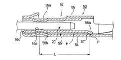
図1は本発明の一実施形態に係る雌端子の縦断面図であり、図2は図1に示した雌端子に雄端子を挿入した際の状態を示す要部拡大断面図である。
【0014】
本実施形態の雌端子50は、図1及び図2に示すように、図示しない電線の端部が接続される電線接続部53の前側に、雄端子20を挿入し電気接続するための相手端子挿入部52を有している。
矩形筒状の前記相手端子挿入部52には、底壁54の前端縁から後方に向かって延び、且つ自由端部56aが前記底壁54上を摺動可能とされた弾性接触片56が設けられている。
【0015】
前記弾性接触片56は、底壁54の前端縁に一体化されており、中間部56bには天壁55に形成した湾曲部55aに向かってアーチ形に湾曲形成された湾曲部56dを有し、自由端部6aには前記底壁54に向かって突出した凸部57が設けられている。
前記凸部57は、雄端子20の挿入による該弾性接触片56の弾性変形時に前記底壁54上に接触することにより、その接触部分より前側の部分を前記底壁54から浮かせるように、底壁54に向かって突出する半円弧状断面を有するように屈曲形成されている。
【0016】
即ち、本実施形態の雌端子50は、図2に示したように、弾性接触片56の自由端部56aに底壁54に向かって突出する凸部57を設け、該凸部57で底壁54に接触させるようにしているので、その接触部よりも前側の部分では弾性接触片56と底壁54との間に常にクリアランスHを確保することができる。
【0017】
そこで、雄端子20の挿入に応じて弾性接触片56が弾性変形する際に、弾性接触片56の自由端部側の支持点Pが底壁54に対して前側に徐々に移動することがなくなり、弾性接触片56の両端支持点56a,56d間の距離L、つまり実質的なバネ長さが一定に保たれて、一定のバネ定数が維持される。
【0018】
従って、雄端子20の挿入に伴って挿入抵抗が高くなるようなことがなく、常に一定の力で雄端子20を挿入することができる。また、雄端子20の挿入に応じて弾性接触片56の両端支持点56a,56d間の距離Lが変わらず、弾性接触片56のバネ定数を一定に保つことができるので、雄端子20の公差範囲内での誤差による弾性接触片56の接触荷重の変化も小さくすることができ、品質管理が容易となり、生産性の向上にも寄与することができる。
【0019】
尚、本発明の雌端子における弾性接触片及び凸部の構成は、上記実施形態における弾性接触片56及び凸部57の構成に限定されるものではなく、本発明の趣旨に基づいて種々の形態を採りうることは云うまでもない。
例えば、前記凸部をプレス時に半球状に膨出させた突起で形成することもできる。
【0020】
【発明の効果】
以上説明したように、本発明の雌端子によれば、弾性接触片の自由端部に底壁に向かって突出する凸部を設け、該凸部で底壁に接触させるようにしているので、その接触部よりも前側の部分では弾性接触片と底壁との間に常にクリアランスを確保することができる。
そこで、雄端子の挿入に応じて弾性接触片が弾性変形する際に、弾性接触片の自由端部側の支持点が底壁に対して前側に徐々に移動することがなくなり、弾性接触片の両端支持点間の距離、つまり実質的なバネ長さが一定に保たれて、一定のバネ定数が維持される。
【0021】
従って、雄端子の挿入に伴って挿入抵抗が高くなるようなことがなく、常に一定の力で雄端子を挿入することができる。また、雄端子の挿入に応じて弾性接触片の両端支持点間の距離が変わらず、弾性接触片のバネ定数を一定に保つことができるので、雄端子の公差範囲内での誤差による弾性接触片の接触荷重の変化も小さくすることができ、品質管理が容易となり、生産性の向上にも寄与することができる。
【図面の簡単な説明】
【図1】本発明の一実施形態に係る雌端子の縦断面図である。
【図2】図1に示した雌端子に雄端子を挿入した際の状態を示す要部拡大断面図である。
【図3】従来の雌端子の縦断面図である。
【図4】図3に示した雌端子に雄端子を挿入した際の状態を示す要部拡大断面図である。
【符号の説明】
20 雄端子
50 雌端子
52 相手端子挿入部
54 底壁
55 天壁
56 弾性接触片
56a 自由端部
57 凸部[0001]
TECHNICAL FIELD OF THE INVENTION
The present invention relates to a female terminal provided with an elastic contact piece which extends rearward from a front end edge of a bottom wall in a cylindrical counterpart terminal insertion portion and whose free end is slidable on the bottom wall. Regarding improvement.
[0002]
[Prior art]
As a conventional female terminal, a rectangular cylindrical mating terminal insertion portion is provided on the front side of the electric wire connection portion, an elastic contact piece is provided in the mating terminal insertion portion, and the male terminal inserted into the mating terminal insertion portion is provided. There is known a female terminal that is sandwiched between the elastic contact piece and a top wall of a mating terminal insertion portion (for example, see Patent Document 1).
[0003]
3 and 4 are a cross-sectional view and a main part enlarged view showing the configuration of a conventional female terminal.
As shown in FIGS. 3 and 4, the
The cylindrical
[0004]
The elastic contact piece 6 is integrated with the front edge of the bottom wall 4, the
[0005]
Then, as shown in FIG. 4, when the
In this state, the
[0006]
[Patent Document 1]
JP-A-9-289055 (FIG. 2)
[0007]
[Problems to be solved by the invention]
By the way, in the above-mentioned conventional
[0008]
As a result, there is a problem in that the spring constant increases due to the decrease in the distance L between the support points at both ends, and the insertion force (insertion resistance) of the
[0009]
SUMMARY OF THE INVENTION Accordingly, an object of the present invention is to solve the above-mentioned problems, and to provide a good female terminal capable of reducing the insertion force of a male terminal and easily managing a contact load.
[0010]
[Means for Solving the Problems]
The above object of the present invention is such that, as set forth in
The free end of the elastic contact piece protrudes toward the bottom wall, and contacts the bottom wall when the elastic contact piece is elastically deformed by insertion of a mating terminal, so that the contact portion is located on the front side of the contact portion. This is achieved by a female terminal, characterized in that a convex portion for lifting a portion from the bottom wall is provided.
[0011]
According to the female terminal having the above-described configuration, since the convex portion protruding toward the bottom wall is provided at the free end of the elastic contact piece, and the convex portion is brought into contact with the bottom wall, the front side of the contact portion is provided. The clearance can always be ensured between the elastic contact piece and the bottom wall at the portion.
Therefore, when the elastic contact piece is elastically deformed in response to the insertion of the male terminal, the support point on the free end side of the elastic contact piece does not gradually move forward with respect to the bottom wall. The distance between the end support points, that is, the substantial spring length is kept constant, and a constant spring constant is maintained.
[0012]
Therefore, the insertion resistance does not increase with the insertion of the male terminal, and the male terminal can always be inserted with a constant force. Also, the distance between the support points at both ends of the elastic contact piece does not change according to the insertion of the male terminal, and the spring constant of the elastic contact piece can be kept constant, so that the elastic contact due to an error within the tolerance range of the male terminal can be maintained. The change in the contact load of the piece can be reduced, quality control becomes easy, and it can contribute to improvement in productivity.
[0013]
BEST MODE FOR CARRYING OUT THE INVENTION
Hereinafter, a female terminal according to an embodiment of the present invention will be described in detail with reference to the accompanying drawings.
FIG. 1 is a longitudinal sectional view of a female terminal according to an embodiment of the present invention, and FIG. 2 is an enlarged sectional view of a main part showing a state when a male terminal is inserted into the female terminal shown in FIG.
[0014]
As shown in FIGS. 1 and 2, the
The mating terminal insertion portion 52 having a rectangular cylindrical shape is provided with an
[0015]
The
The
[0016]
That is, as shown in FIG. 2, the
[0017]
Therefore, when the
[0018]
Therefore, the insertion resistance does not increase with the insertion of the
[0019]
In addition, the configuration of the elastic contact piece and the convex portion in the female terminal of the present invention is not limited to the configuration of the
For example, the protrusion may be formed by a protrusion which bulges into a hemisphere at the time of pressing.
[0020]
【The invention's effect】
As described above, according to the female terminal of the present invention, the free end of the elastic contact piece is provided with the convex portion protruding toward the bottom wall, and the convex portion is brought into contact with the bottom wall. A clearance can always be ensured between the elastic contact piece and the bottom wall in a portion on the front side of the contact portion.
Therefore, when the elastic contact piece is elastically deformed in response to the insertion of the male terminal, the support point on the free end side of the elastic contact piece does not gradually move forward with respect to the bottom wall. The distance between the end support points, that is, the substantial spring length is kept constant, and a constant spring constant is maintained.
[0021]
Therefore, the insertion resistance does not increase with the insertion of the male terminal, and the male terminal can always be inserted with a constant force. Also, the distance between the support points at both ends of the elastic contact piece does not change according to the insertion of the male terminal, and the spring constant of the elastic contact piece can be kept constant. The change in the contact load of the piece can be reduced, quality control can be facilitated, and the productivity can be improved.
[Brief description of the drawings]
FIG. 1 is a longitudinal sectional view of a female terminal according to an embodiment of the present invention.
FIG. 2 is an enlarged sectional view of a main part showing a state when a male terminal is inserted into the female terminal shown in FIG.
FIG. 3 is a longitudinal sectional view of a conventional female terminal.
FIG. 4 is an enlarged sectional view of a main part showing a state when a male terminal is inserted into the female terminal shown in FIG. 3;
[Explanation of symbols]
Claims (1)
前記弾性接触片の自由端部には、前記底壁に向かって突出し、且つ、相手端子の挿入による該弾性接触片の弾性変形時に前記底壁上に接触することにより、その接触部分より前側の部分を前記底壁から浮かせる凸部が設けられていることを特徴とする雌端子。A female terminal provided with an elastic contact piece extending rearward from a front end edge of a bottom wall in a cylindrical counterpart terminal insertion portion and having a free end slidable on the bottom wall,
The free end of the elastic contact piece protrudes toward the bottom wall, and contacts the bottom wall when the elastic contact piece is elastically deformed by insertion of a mating terminal, so that the contact portion is located on the front side of the contact portion. A female terminal provided with a convex portion for lifting a portion from the bottom wall.
Priority Applications (2)
| Application Number | Priority Date | Filing Date | Title |
|---|---|---|---|
| JP2003039687A JP2004253166A (en) | 2003-02-18 | 2003-02-18 | Female terminal |
| US10/779,880 US20040224573A1 (en) | 2003-02-18 | 2004-02-18 | Female terminal |
Applications Claiming Priority (1)
| Application Number | Priority Date | Filing Date | Title |
|---|---|---|---|
| JP2003039687A JP2004253166A (en) | 2003-02-18 | 2003-02-18 | Female terminal |
Publications (1)
| Publication Number | Publication Date |
|---|---|
| JP2004253166A true JP2004253166A (en) | 2004-09-09 |
Family
ID=33023796
Family Applications (1)
| Application Number | Title | Priority Date | Filing Date |
|---|---|---|---|
| JP2003039687A Pending JP2004253166A (en) | 2003-02-18 | 2003-02-18 | Female terminal |
Country Status (2)
| Country | Link |
|---|---|
| US (1) | US20040224573A1 (en) |
| JP (1) | JP2004253166A (en) |
Cited By (1)
| Publication number | Priority date | Publication date | Assignee | Title |
|---|---|---|---|---|
| KR101389172B1 (en) | 2011-11-02 | 2014-04-24 | 스미토모 덴소 가부시키가이샤 | Female terminal fitting and production method therefor |
Families Citing this family (11)
| Publication number | Priority date | Publication date | Assignee | Title |
|---|---|---|---|---|
| US20060292937A1 (en) * | 2005-06-23 | 2006-12-28 | Morello John R | Electrical connector having dual contact function spring contact terminal |
| US7252564B1 (en) * | 2006-01-27 | 2007-08-07 | Delphi Technologies, Inc. | Female electrical connector having crimping portions of double thickness |
| JP4858293B2 (en) * | 2007-05-08 | 2012-01-18 | 住友電装株式会社 | Female terminal bracket |
| US8272901B2 (en) * | 2010-09-21 | 2012-09-25 | Tyco Electronics Corporation | Crimp contacts and electrical connector assemblies including the same |
| JP2014160545A (en) * | 2013-02-19 | 2014-09-04 | Sumitomo Wiring Syst Ltd | Female terminal metal fitting |
| JP2014170709A (en) * | 2013-03-05 | 2014-09-18 | Sumitomo Wiring Syst Ltd | Female terminal fitting |
| US9118130B1 (en) * | 2014-02-06 | 2015-08-25 | Delphi Technologies, Inc. | Low insertion force terminal |
| CN103811906B (en) * | 2014-02-10 | 2019-02-12 | 连展科技电子(昆山)有限公司 | The terminal of electric connector |
| JP6776050B2 (en) * | 2016-08-01 | 2020-10-28 | 日本航空電子工業株式会社 | Female terminal and connector with it |
| JP7052665B2 (en) * | 2018-10-02 | 2022-04-12 | 株式会社オートネットワーク技術研究所 | Female terminal |
| JP7176372B2 (en) * | 2018-11-27 | 2022-11-22 | I-Pex株式会社 | terminal |
Family Cites Families (6)
| Publication number | Priority date | Publication date | Assignee | Title |
|---|---|---|---|---|
| JP3067545B2 (en) * | 1994-09-09 | 2000-07-17 | 住友電装株式会社 | Female terminal fitting |
| JPH0945404A (en) * | 1995-07-28 | 1997-02-14 | Yazaki Corp | Female terminal |
| JP3807646B2 (en) * | 1997-10-31 | 2006-08-09 | 矢崎総業株式会社 | Terminal sag prevention structure |
| JP2002063961A (en) * | 2000-06-07 | 2002-02-28 | Yazaki Corp | Female terminal, and connecting structure of female terminal with male terminal |
| JP3875526B2 (en) * | 2001-08-10 | 2007-01-31 | 矢崎総業株式会社 | Terminal spring structure |
| JP3415138B1 (en) * | 2002-06-06 | 2003-06-09 | 住友電装株式会社 | connector |
-
2003
- 2003-02-18 JP JP2003039687A patent/JP2004253166A/en active Pending
-
2004
- 2004-02-18 US US10/779,880 patent/US20040224573A1/en not_active Abandoned
Cited By (1)
| Publication number | Priority date | Publication date | Assignee | Title |
|---|---|---|---|---|
| KR101389172B1 (en) | 2011-11-02 | 2014-04-24 | 스미토모 덴소 가부시키가이샤 | Female terminal fitting and production method therefor |
Also Published As
| Publication number | Publication date |
|---|---|
| US20040224573A1 (en) | 2004-11-11 |
Similar Documents
| Publication | Publication Date | Title |
|---|---|---|
| JP5251819B2 (en) | Female terminal bracket | |
| JP4858293B2 (en) | Female terminal bracket | |
| JP4483601B2 (en) | Female terminal bracket | |
| JP5375564B2 (en) | Terminal fitting | |
| JP2546255Y2 (en) | Female terminal fitting | |
| JP6229742B2 (en) | Female terminal and method for manufacturing female terminal | |
| US20140287635A1 (en) | Terminal fitting | |
| JP2004253166A (en) | Female terminal | |
| JP2011181330A (en) | Terminal fitting | |
| JP2003346957A (en) | Terminal metal | |
| CN111433977B (en) | Terminal with a terminal body | |
| JP2009176617A (en) | Terminals, and terminal connecting structure | |
| JP2011249169A (en) | Terminal fitting | |
| JP3814221B2 (en) | Male terminal fitting | |
| JP2011129271A (en) | Terminal fitting | |
| JP2004362832A (en) | Terminal fitting | |
| JP2011086540A (en) | Connection structure of terminal metal fitting | |
| JP5343779B2 (en) | Terminal fitting | |
| WO2015115363A1 (en) | Terminal connection structure | |
| US8272905B2 (en) | Structure for a terminal in an electric connector | |
| JP2011119105A (en) | Connection structure of terminal fitting | |
| JP2003346958A (en) | Female terminal metal | |
| JP5561551B2 (en) | Female terminal fitting | |
| JPH11233181A (en) | Female side terminal metal fixture | |
| JP6116339B2 (en) | Plate terminal |
Legal Events
| Date | Code | Title | Description |
|---|---|---|---|
| A621 | Written request for application examination |
Free format text: JAPANESE INTERMEDIATE CODE: A621 Effective date: 20051025 |
|
| RD04 | Notification of resignation of power of attorney |
Free format text: JAPANESE INTERMEDIATE CODE: A7424 Effective date: 20060325 |
|
| A977 | Report on retrieval |
Free format text: JAPANESE INTERMEDIATE CODE: A971007 Effective date: 20060410 |
|
| A131 | Notification of reasons for refusal |
Free format text: JAPANESE INTERMEDIATE CODE: A131 Effective date: 20060426 |
|
| A521 | Written amendment |
Free format text: JAPANESE INTERMEDIATE CODE: A523 Effective date: 20060619 |
|
| A02 | Decision of refusal |
Free format text: JAPANESE INTERMEDIATE CODE: A02 Effective date: 20061004 |