EP1171397B1 - Method of sealing glass - Google Patents
Method of sealing glass Download PDFInfo
- Publication number
- EP1171397B1 EP1171397B1 EP00925467A EP00925467A EP1171397B1 EP 1171397 B1 EP1171397 B1 EP 1171397B1 EP 00925467 A EP00925467 A EP 00925467A EP 00925467 A EP00925467 A EP 00925467A EP 1171397 B1 EP1171397 B1 EP 1171397B1
- Authority
- EP
- European Patent Office
- Prior art keywords
- indium
- glass
- pieces
- indium alloy
- seal
- Prior art date
- Legal status (The legal status is an assumption and is not a legal conclusion. Google has not performed a legal analysis and makes no representation as to the accuracy of the status listed.)
- Expired - Lifetime
Links
- 238000000034 method Methods 0.000 title claims abstract description 43
- 239000005394 sealing glass Substances 0.000 title 1
- 239000011521 glass Substances 0.000 claims abstract description 85
- APFVFJFRJDLVQX-UHFFFAOYSA-N indium atom Chemical compound [In] APFVFJFRJDLVQX-UHFFFAOYSA-N 0.000 claims abstract description 82
- 229910052738 indium Inorganic materials 0.000 claims abstract description 76
- 229910000846 In alloy Inorganic materials 0.000 claims abstract description 62
- 239000002184 metal Substances 0.000 claims abstract description 26
- 229910052751 metal Inorganic materials 0.000 claims abstract description 26
- 238000010438 heat treatment Methods 0.000 claims abstract description 15
- 238000000576 coating method Methods 0.000 claims description 13
- 238000007789 sealing Methods 0.000 claims description 8
- RYGMFSIKBFXOCR-UHFFFAOYSA-N Copper Chemical compound [Cu] RYGMFSIKBFXOCR-UHFFFAOYSA-N 0.000 claims description 7
- 229910052802 copper Inorganic materials 0.000 claims description 7
- 239000010949 copper Substances 0.000 claims description 7
- 238000005476 soldering Methods 0.000 claims description 5
- 239000005341 toughened glass Substances 0.000 claims description 5
- 239000011248 coating agent Substances 0.000 claims description 4
- 238000000151 deposition Methods 0.000 claims description 4
- 239000010935 stainless steel Substances 0.000 claims description 3
- 229910001220 stainless steel Inorganic materials 0.000 claims description 3
- ATJFFYVFTNAWJD-UHFFFAOYSA-N Tin Chemical compound [Sn] ATJFFYVFTNAWJD-UHFFFAOYSA-N 0.000 claims description 2
- 229910052709 silver Inorganic materials 0.000 claims description 2
- 239000004332 silver Substances 0.000 claims description 2
- 230000015572 biosynthetic process Effects 0.000 abstract description 3
- XEEYBQQBJWHFJM-UHFFFAOYSA-N Iron Chemical compound [Fe] XEEYBQQBJWHFJM-UHFFFAOYSA-N 0.000 description 4
- 238000004519 manufacturing process Methods 0.000 description 4
- 230000000694 effects Effects 0.000 description 3
- 238000001771 vacuum deposition Methods 0.000 description 3
- 229910001128 Sn alloy Inorganic materials 0.000 description 2
- 229910045601 alloy Inorganic materials 0.000 description 2
- 239000000956 alloy Substances 0.000 description 2
- 230000008021 deposition Effects 0.000 description 2
- 238000005516 engineering process Methods 0.000 description 2
- 229910052742 iron Inorganic materials 0.000 description 2
- 150000002739 metals Chemical class 0.000 description 2
- 238000011176 pooling Methods 0.000 description 2
- 238000003825 pressing Methods 0.000 description 2
- 229910000679 solder Inorganic materials 0.000 description 2
- 238000002834 transmittance Methods 0.000 description 2
- 229910001316 Ag alloy Inorganic materials 0.000 description 1
- 229910000831 Steel Inorganic materials 0.000 description 1
- 238000004378 air conditioning Methods 0.000 description 1
- 230000015556 catabolic process Effects 0.000 description 1
- 238000004140 cleaning Methods 0.000 description 1
- 238000013034 coating degradation Methods 0.000 description 1
- 230000008602 contraction Effects 0.000 description 1
- 238000006731 degradation reaction Methods 0.000 description 1
- 230000001419 dependent effect Effects 0.000 description 1
- 239000003599 detergent Substances 0.000 description 1
- -1 indium/tin alloys Chemical compound 0.000 description 1
- 239000000463 material Substances 0.000 description 1
- 238000002844 melting Methods 0.000 description 1
- 230000008018 melting Effects 0.000 description 1
- 238000010943 off-gassing Methods 0.000 description 1
- 230000003287 optical effect Effects 0.000 description 1
- 230000002035 prolonged effect Effects 0.000 description 1
- 230000005855 radiation Effects 0.000 description 1
- 239000000565 sealant Substances 0.000 description 1
- 238000000926 separation method Methods 0.000 description 1
- 239000002904 solvent Substances 0.000 description 1
- 239000010959 steel Substances 0.000 description 1
- 230000035882 stress Effects 0.000 description 1
- 230000008646 thermal stress Effects 0.000 description 1
Images


Classifications
-
- E—FIXED CONSTRUCTIONS
- E06—DOORS, WINDOWS, SHUTTERS, OR ROLLER BLINDS IN GENERAL; LADDERS
- E06B—FIXED OR MOVABLE CLOSURES FOR OPENINGS IN BUILDINGS, VEHICLES, FENCES OR LIKE ENCLOSURES IN GENERAL, e.g. DOORS, WINDOWS, BLINDS, GATES
- E06B3/00—Window sashes, door leaves, or like elements for closing wall or like openings; Layout of fixed or moving closures, e.g. windows in wall or like openings; Features of rigidly-mounted outer frames relating to the mounting of wing frames
- E06B3/66—Units comprising two or more parallel glass or like panes permanently secured together
- E06B3/663—Elements for spacing panes
- E06B3/66304—Discrete spacing elements, e.g. for evacuated glazing units
-
- C—CHEMISTRY; METALLURGY
- C03—GLASS; MINERAL OR SLAG WOOL
- C03C—CHEMICAL COMPOSITION OF GLASSES, GLAZES OR VITREOUS ENAMELS; SURFACE TREATMENT OF GLASS; SURFACE TREATMENT OF FIBRES OR FILAMENTS MADE FROM GLASS, MINERALS OR SLAGS; JOINING GLASS TO GLASS OR OTHER MATERIALS
- C03C27/00—Joining pieces of glass to pieces of other inorganic material; Joining glass to glass other than by fusing
- C03C27/06—Joining glass to glass by processes other than fusing
- C03C27/08—Joining glass to glass by processes other than fusing with the aid of intervening metal
-
- E—FIXED CONSTRUCTIONS
- E06—DOORS, WINDOWS, SHUTTERS, OR ROLLER BLINDS IN GENERAL; LADDERS
- E06B—FIXED OR MOVABLE CLOSURES FOR OPENINGS IN BUILDINGS, VEHICLES, FENCES OR LIKE ENCLOSURES IN GENERAL, e.g. DOORS, WINDOWS, BLINDS, GATES
- E06B3/00—Window sashes, door leaves, or like elements for closing wall or like openings; Layout of fixed or moving closures, e.g. windows in wall or like openings; Features of rigidly-mounted outer frames relating to the mounting of wing frames
- E06B3/66—Units comprising two or more parallel glass or like panes permanently secured together
- E06B3/673—Assembling the units
- E06B3/67326—Assembling spacer elements with the panes
-
- E—FIXED CONSTRUCTIONS
- E06—DOORS, WINDOWS, SHUTTERS, OR ROLLER BLINDS IN GENERAL; LADDERS
- E06B—FIXED OR MOVABLE CLOSURES FOR OPENINGS IN BUILDINGS, VEHICLES, FENCES OR LIKE ENCLOSURES IN GENERAL, e.g. DOORS, WINDOWS, BLINDS, GATES
- E06B3/00—Window sashes, door leaves, or like elements for closing wall or like openings; Layout of fixed or moving closures, e.g. windows in wall or like openings; Features of rigidly-mounted outer frames relating to the mounting of wing frames
- E06B3/66—Units comprising two or more parallel glass or like panes permanently secured together
- E06B3/673—Assembling the units
- E06B3/67326—Assembling spacer elements with the panes
- E06B3/67334—Assembling spacer elements with the panes by soldering; Preparing the panes therefor
-
- E—FIXED CONSTRUCTIONS
- E06—DOORS, WINDOWS, SHUTTERS, OR ROLLER BLINDS IN GENERAL; LADDERS
- E06B—FIXED OR MOVABLE CLOSURES FOR OPENINGS IN BUILDINGS, VEHICLES, FENCES OR LIKE ENCLOSURES IN GENERAL, e.g. DOORS, WINDOWS, BLINDS, GATES
- E06B3/00—Window sashes, door leaves, or like elements for closing wall or like openings; Layout of fixed or moving closures, e.g. windows in wall or like openings; Features of rigidly-mounted outer frames relating to the mounting of wing frames
- E06B3/66—Units comprising two or more parallel glass or like panes permanently secured together
- E06B3/673—Assembling the units
- E06B3/67339—Working the edges of already assembled units
- E06B3/6736—Heat treatment
-
- E—FIXED CONSTRUCTIONS
- E06—DOORS, WINDOWS, SHUTTERS, OR ROLLER BLINDS IN GENERAL; LADDERS
- E06B—FIXED OR MOVABLE CLOSURES FOR OPENINGS IN BUILDINGS, VEHICLES, FENCES OR LIKE ENCLOSURES IN GENERAL, e.g. DOORS, WINDOWS, BLINDS, GATES
- E06B3/00—Window sashes, door leaves, or like elements for closing wall or like openings; Layout of fixed or moving closures, e.g. windows in wall or like openings; Features of rigidly-mounted outer frames relating to the mounting of wing frames
- E06B3/66—Units comprising two or more parallel glass or like panes permanently secured together
- E06B3/677—Evacuating or filling the gap between the panes ; Equilibration of inside and outside pressure; Preventing condensation in the gap between the panes; Cleaning the gap between the panes
- E06B3/6775—Evacuating or filling the gap during assembly
Definitions
- This invention relates to a method of forming an air-tight seal between two pieces of glass, particularly but not exclusively two panes of glass to form an evacuated double glazing unit.
- Evacuated glazing generally consists of two glass sheets separated by a regular array of support pillars, typically 0.2mm high.
- a contiguous seal provides an air-tight unit which is in general evacuated to 0.1Pa or less to reduce gaseous conduction to a minimal level.
- vacuum glazing units have only been manufactured using a solder glass seal formed at temperatures above 400°C between the glass pieces. The air is subsequently pumped out from between the pieces using a pump-out tube.
- present evacuated glazing units are limited to using hard-coated types of low-emittance films or coatings on their internal glass surfaces, and cannot be made with tempered glass. Many high performance low emittance coatings cannot at present survive temperatures in excess of 200°C or so for any prolonged period of time.
- Low emittance coatings reduce long wave radiative heat transfer through the glazing unit.
- hard coatings have in general higher emittance to long-wave radiation in the range 2.5-30 ⁇ m than soft-coated films, which have emittances ⁇ 0.1.
- a method of forming an air-tight seal between two pieces of glass comprising the steps of:
- Indium, or indium alloy has been found to be particularly useful in forming an air-tight seal between two pieces of glass, once the indium or indium alloy has been suitably positioned onto the glass, made molten, and then cooled.
- a layer of indium or indium alloy is added onto each piece of glass (prior to heating) in the region of the seal, and this can be carried out using any of the known and suitable metal-glass deposition or bonding techniques.
- any coating or film on the glass is removed from at least the intended area of the seal prior to the application of indium or indium alloy to such glass.
- the glass is preferably cleaned and/or baked prior to the application of the indium or indium alloy.
- the glass pieces with the layer(s) of indium or indium alloy are heated to a uniform temperature to provide constant and equivalent bonding at each and every location, and more preferably a relatively slow heating regime is used.
- the heating temperature is dependent on which indium or indium alloy is used. Most if not all suitable materials melt at 220°C or less, generally 200°C or less. Therefore, the temperature of the heating should generally not exceed 220°C, and will commonly be below 200°C.
- one or more, preferably one, additional metal layers can be located between the indium or indium alloy surface films.
- Such metal layer could be in the form of a wire or a gasket, etc.
- the metal layer could be made from any suitable metal or alloy able to bond with indium or indium alloy.
- Such metals include indium or an indium alloy, or other metals eg copper or steel such as stainless steel.
- Such other metal layers could be added per se, or pre-coated with indium or a suitable indium alloy to assist bonding when heated.
- an intermediate metal layer assists if the deposited layers of indium or indium alloy on the glass pieces are not of the correct thickness or uniformity to allow them to meet and so bond together when they and the glass pieces are heated, and/or to generally increase the separation between the glass pieces, and/or to reduce the thickness of the indium or indium alloy surface film required, and/or to provide good inter-metal bonding.
- the heating temperature and regime depends upon the indium or which indium alloy is used.
- the layers of indium or indium alloy are provided as the coating around a suitable support such as a metal wire or gasket, which coated support is placed directly between the glass pieces and heated, preferably with associated pressure, to form the seal.
- a suitable support such as a metal wire or gasket
- the thickness of the seal of the present invention may be similar to the thickness of existing seals, e.g. between 0.05-0.2mm or more. Intermediate support pillars between glass panes are commonly about 0.1-0.2mm in height. The width of the seal may again be similar to that of existing seals, e.g. between 3-10mm.
- the pieces of glass could be of any suitable size, shape or design, between which a seal is desired.
- the two pieces need not be similar in size, shape or design.
- the present invention is suitable to form a relatively small air-type seal between two glass panes or sheets.
- the invention is particularly suitable for the formation of evacuated double glazing units. Thus preferably, the heating to form the seal is conducted under vacuum.
- Larger glazing units can also be formed by the present invention using additional sheets of glass to provide eg triple glazing units with either one or two of the inner spaces between the three sheets evacuated.
- Triple glazing can be used to minimise wind loading on vacuum glazing, and allow larger panes to be utilised.
- the normal spacing for double glazing could still be used between the evacuated component and a third glass sheet.
- An advantage of the use of a third glass pane is a reduction in thermal gradients, and thus reduction in expansion/contraction of the vacuum glazing unit, and subsequent induced thermal stress.
- One or more of the glass pieces being sealed by the present invention could also be coated to minimise solar gain and thus make the vacuum glazing unit suitable for use in hot climates (with a consequent large reduction in any air conditioning load).
- This allows the introduction of additional glazing technologies such as electrochromics, photochromics and thermochromics, which enable the glazing to be changed from transparent to opaque.
- Such technologies cannot be used with existing sealing techniques, the temperatures for which are so high as to destroy the chromicity.
- the invention is also suitable for sealing holes or apertures in a piece of glass, e.g. a pump-out hole.
- the indium or indium alloy could be added around the hole or aperture, and similarly layered on a glass cover piece, not necessarily being flat.
- Figure 1 shows two panes of glass 2 suitable for forming a double glazing unit. Along the edges of each pane 2, there is a layer of indium 4. Between the indium layers 4, there is shown pieces of indium wire 6 which may be required should the indium layers 4 not meet when the panes 2 are brought together. Figure 1 also shows an array of pillars 8 to provide support between the panes 2.
- the forming of the seal maybe be performed in the following manner.
- the glass panes, either with or without low emittance coatings, can be cleaned using suitable solvents and/or detergents.
- the cleaned panes can then be baked out for a period of time at a temperature less than that resulting in degradation of any coatings. If the coatings are incompatible with the indium or indium alloy, they should be removed in the location of the intended seal.
- the indium films are then deposited onto the surfaces of both glass panes in the region of the intended seal, either using a vacuum deposition technique, or an ultrasonic soldering iron or other known methods suitable to bond indium to glass.
- the pillar array is then arranged between the panes.
- indium or indium alloy wire or a gasket is located between the indium films.
- Vacuum deposition can deposit layers of indium or indium alloy up to 1 ⁇ m thick. Ultrasonic soldering can deposit thicker layers.
- a vacuum chamber is evacuated to a pressure of less than 0.1Pa, with the panes and the indium or indium alloy therein.
- the heat is then supplied, possibly using radiant heaters or a heat platen, to raise the temperature of the glass and the indium or indium alloy to a temperature at which the indium or indium alloy films, and any wire, etc, fuse.
- this temperature is approximately 157°C.
- Some indium alloys have lower temperature requirements, others slightly higher.
- the temperature can be reduced by applying pressure, generally on the top glass pane.
- the temperature is uniform and is less than that at which the indium could flow and so to avoid causing gaps in the seal and local pooling effects.
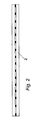
- Figure 2 shows a formed unit.
- the vacuum in the double glazing unit can be formed using the pump-out tube method.
- a pump-out tube is located in the upper glass pane prior to any cleaning and the deposition of any indium or indium alloy.
- the lower glass pane is generally located in an oven or on a heated platen, with the upper sheet positioned so that the two deposited indium or indium alloy surfaces are touching.
- Heat is applied to raise the temperature of the glass and the indium or indium alloy to a temperature at which the indium or indium alloy films and any wire etc, fuse. Again the temperature can be reduced by applying pressure, and it is preferred that the temperature is uniform and is less than that at which the indium could flow to cause gaps in the seal and local pooling effects.
- a vacuum reservoir is attached to the pump-out tube and used to evacuate the glazing unit to a pressure of less than 0.1Pa.
- An electrical resistance heater is used to seal the pump-out tube.
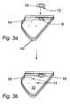
- the pump-out hole is sealed as shown in Figures 3a and 3b .
- a thin ring of indium or indium alloy 9 is deposited around the small diameter hole 14 pre-drilled into one of the two glass sheets 10, (between which sheets 10 is also a pillar array 11).
- a thin ring of indium or indium alloy 12 is also coated onto a glass cover slide 16 of radius approximately 7.5mm with a bevelled upper edge.
- the glass cover slide 16 is located over the pump-out hole 14 so that the two rings of indium or indium alloy 9,12 substantially mate.
- a vacuum cup fitting (not shown) is located on to the glass surface 10 so that the cover slide 16 is completely enclosed within it.
- a small heater element within the vacuum fitting locates over the cover slide 16 and holds it in location while vacuum pump-out occurs through the natural gaps between indium or indium alloy layers 9, 12.
- the main sealants used are indiums, or an indium alloy formed with one or more of the group comprising tin, silver and lead, such as indium/tin alloys, indium/tin/silver alloys, or other indium based alloys with the desired melting temperatures, bonding and strength characteristics.
- a vacuum edge seal may also be formed as shown in Figure 4.
- Figure 4 shows two panes of glass 20, and on both panes of glass 20 in the region adjacent to the edge are thin layers of indium or indium alloy 22. These layers of indium or indium alloy can be laid down using an ultrasonic soldering iron or preferably via vacuum deposition. Between the indium layers 22 is a thin metal gasket 24 made for example from copper. Copper and indium bond well together, and the use of a copper gasket allows the use of micro layers of indium on the glass, which should reduce cost.
- the copper gasket 24 is deposited on the indium layer 22 of the lower glass pane 20, and the indium layer 22 on the face of the upper glass pane 20 is then located on the metal gasket 24. Heating the unit as mentioned above forms seals between the indium layers 22 and the metal gasket 24.
- the sealing mechanism could be performed in vacuum, or in an oven with subsequent pump-out via a pump-out tube, as described above.
- the present invention provides a method of fabricating seals between glass pieces, in particular evacuated double or multiple glazing units at relatively low temperatures. These allow the use of soft coatings such as those consisting of multiple dielectric/metal/dielectric layers on glass, to give optimal thermal and optical performance. With reduced rates of heat transfer through the glazing unit, there is lower heat loss in buildings with high visible transmittance.
- Such glazing units could also be used eg for transparent doors for refrigerators, or solar energy collector covers, or in conjunction with electrochromics, photochromics or thermochromics.
- the use of low fabrication temperatures also reduces embodied energy, and reduces any possible film or coating degradation during the fabrication process, and reduces stress in the region of the edge seal system.
Landscapes
- Engineering & Computer Science (AREA)
- Chemical & Material Sciences (AREA)
- Civil Engineering (AREA)
- Structural Engineering (AREA)
- Life Sciences & Earth Sciences (AREA)
- General Chemical & Material Sciences (AREA)
- Geochemistry & Mineralogy (AREA)
- Materials Engineering (AREA)
- Organic Chemistry (AREA)
- Chemical Kinetics & Catalysis (AREA)
- Ceramic Engineering (AREA)
- Joining Of Glass To Other Materials (AREA)
- Glass Compositions (AREA)
Abstract
Description
- This invention relates to a method of forming an air-tight seal between two pieces of glass, particularly but not exclusively two panes of glass to form an evacuated double glazing unit.
- Low heat loss and high total solar transmittance can be obtained from a contiguously-sealed double glazing unit with an evacuated gap. Evacuated glazing generally consists of two glass sheets separated by a regular array of support pillars, typically 0.2mm high. A contiguous seal provides an air-tight unit which is in general evacuated to 0.1Pa or less to reduce gaseous conduction to a minimal level.
- Presently, vacuum glazing units have only been manufactured using a solder glass seal formed at temperatures above 400°C between the glass pieces. The air is subsequently pumped out from between the pieces using a pump-out tube. However, because of the need for such high temperatures to produce the solder glass edge seal, present evacuated glazing units are limited to using hard-coated types of low-emittance films or coatings on their internal glass surfaces, and cannot be made with tempered glass. Many high performance low emittance coatings cannot at present survive temperatures in excess of 200°C or so for any prolonged period of time.
- Low emittance coatings reduce long wave radiative heat transfer through the glazing unit. However, hard coatings have in general higher emittance to long-wave radiation in the range 2.5-30µm than soft-coated films, which have emittances <0.1.
- Griffiths et al disclose the fabrication of evacuated glazing using indium or indium alloy (Solar Energy, Vol. 63, .
- It is an object of the present invention to provide a method of forming an air-tight seal between two pieces, particularly panes, of glass at temperatures around or below 220°C, so as to allow the use of high performance, i.e. soft-coated, low-emittance coatings and tempered glass.
- According to one aspect of the present invention, there is provided a method of forming an air-tight seal between two pieces of glass comprising the steps of:
- (a) prior to step (b), depositing one or more layers of indium or indium alloy on to each piece of glass in the region of the seal; and
- (b) heating the indium or indium alloy layer(s) and the glass pieces to a temperature to melt the layer(s) and so form the seal between the pieces;
- Indium, or indium alloy, has been found to be particularly useful in forming an air-tight seal between two pieces of glass, once the indium or indium alloy has been suitably positioned onto the glass, made molten, and then cooled.
- A layer of indium or indium alloy is added onto each piece of glass (prior to heating) in the region of the seal, and this can be carried out using any of the known and suitable metal-glass deposition or bonding techniques.
- Preferably, any coating or film on the glass is removed from at least the intended area of the seal prior to the application of indium or indium alloy to such glass. Moreover, the glass is preferably cleaned and/or baked prior to the application of the indium or indium alloy.
- Preferably, the glass pieces with the layer(s) of indium or indium alloy are heated to a uniform temperature to provide constant and equivalent bonding at each and every location, and more preferably a relatively slow heating regime is used. The heating temperature is dependent on which indium or indium alloy is used. Most if not all suitable materials melt at 220°C or less, generally 200°C or less. Therefore, the temperature of the heating should generally not exceed 220°C, and will commonly be below 200°C.
- The use of pressure, e.g. clamps or a weight on the top glass pieces, should reduce the degree of heating required to effect the indium seal between the pieces.
- According to a further embodiment of the present invention, one or more, preferably one, additional metal layers can be located between the indium or indium alloy surface films. Such metal layer could be in the form of a wire or a gasket, etc. The metal layer could be made from any suitable metal or alloy able to bond with indium or indium alloy. Such metals include indium or an indium alloy, or other metals eg copper or steel such as stainless steel. Such other metal layers could be added per se, or pre-coated with indium or a suitable indium alloy to assist bonding when heated.
- The use of an intermediate metal layer assists if the deposited layers of indium or indium alloy on the glass pieces are not of the correct thickness or uniformity to allow them to meet and so bond together when they and the glass pieces are heated, and/or to generally increase the separation between the glass pieces, and/or to reduce the thickness of the indium or indium alloy surface film required, and/or to provide good inter-metal bonding.
- Thus, according to a particular embodiment of the present invention, there is provided a method of forming an air-tight seal between two pieces of glass comprising the steps of;
- (a) adding a layer of indium or indium alloy onto opposing surfaces of the glass pieces in the region of the seal;
- (b) locating an additional metal layer onto one of the indium or indium alloy layers; and
- (c) bringing the glass pieces together to provide contact between the indium or indium alloy layers and the intermediate metal layer, and heating them and the glass pieces to a temperature between 220°-100° centigrade to form a seal between the pieces.
- The heating temperature and regime depends upon the indium or which indium alloy is used.
- In an alternative arrangement, the layers of indium or indium alloy are provided as the coating around a suitable support such as a metal wire or gasket, which coated support is placed directly between the glass pieces and heated, preferably with associated pressure, to form the seal.
- The thickness of the seal of the present invention may be similar to the thickness of existing seals, e.g. between 0.05-0.2mm or more. Intermediate support pillars between glass panes are commonly about 0.1-0.2mm in height. The width of the seal may again be similar to that of existing seals, e.g. between 3-10mm.
- The pieces of glass could be of any suitable size, shape or design, between which a seal is desired. The two pieces need not be similar in size, shape or design. The present invention is suitable to form a relatively small air-type seal between two glass panes or sheets. The invention is particularly suitable for the formation of evacuated double glazing units. Thus preferably, the heating to form the seal is conducted under vacuum.
- Larger glazing units can also be formed by the present invention using additional sheets of glass to provide eg triple glazing units with either one or two of the inner spaces between the three sheets evacuated. Triple glazing can be used to minimise wind loading on vacuum glazing, and allow larger panes to be utilised. The normal spacing for double glazing could still be used between the evacuated component and a third glass sheet. An advantage of the use of a third glass pane is a reduction in thermal gradients, and thus reduction in expansion/contraction of the vacuum glazing unit, and subsequent induced thermal stress.
- One or more of the glass pieces being sealed by the present invention, in particular one or more of the glass panes of a double or multiple gazing unit, could also be coated to minimise solar gain and thus make the vacuum glazing unit suitable for use in hot climates (with a consequent large reduction in any air conditioning load). This allows the introduction of additional glazing technologies such as electrochromics, photochromics and thermochromics, which enable the glazing to be changed from transparent to opaque. Such technologies cannot be used with existing sealing techniques, the temperatures for which are so high as to destroy the chromicity.
- The invention is also suitable for sealing holes or apertures in a piece of glass, e.g. a pump-out hole. The indium or indium alloy could be added around the hole or aperture, and similarly layered on a glass cover piece, not necessarily being flat.
- Embodiments of the present invention will now be described by way of example only with reference to the accompanying drawings in which:
-
Figure 1 shows a schematic cross sectional side view of two bonded glass panes prior to seal being formed; -
Figure 2 shows a schematic cross sectional side view after seal is formed; -
Figure 3a and 3b are schematic perspective views of two glass pieces being bonded according to another embodiment of the present invention; and -
Figure 4 is a part side view of two glass panes to be bonded using a metal gasket thereinbetween. -
Figure 1 shows two panes ofglass 2 suitable for forming a double glazing unit. Along the edges of eachpane 2, there is a layer ofindium 4. Between theindium layers 4, there is shown pieces ofindium wire 6 which may be required should theindium layers 4 not meet when thepanes 2 are brought together.Figure 1 also shows an array ofpillars 8 to provide support between thepanes 2. - The forming of the seal maybe be performed in the following manner. The glass panes, either with or without low emittance coatings, can be cleaned using suitable solvents and/or detergents. The cleaned panes can then be baked out for a period of time at a temperature less than that resulting in degradation of any coatings. If the coatings are incompatible with the indium or indium alloy, they should be removed in the location of the intended seal.
- The indium films are then deposited onto the surfaces of both glass panes in the region of the intended seal, either using a vacuum deposition technique, or an ultrasonic soldering iron or other known methods suitable to bond indium to glass.
- The pillar array is then arranged between the panes.
- If, once the pillar array is positioned, the deposited layers of indium are not of the correct thickness or uniformity to allow them to mate when the top glass pane is located on the pillar array, indium or indium alloy wire or a gasket is located between the indium films. Vacuum deposition can deposit layers of indium or indium alloy up to 1µm thick. Ultrasonic soldering can deposit thicker layers.
- The provision of the vacuum between the panes of a double glazing unit can also be provided in any known manner.
- Using the vacuum chamber evacuation method, a vacuum chamber is evacuated to a pressure of less than 0.1Pa, with the panes and the indium or indium alloy therein. The heat is then supplied, possibly using radiant heaters or a heat platen, to raise the temperature of the glass and the indium or indium alloy to a temperature at which the indium or indium alloy films, and any wire, etc, fuse. For indium this temperature is approximately 157°C. Some indium alloys have lower temperature requirements, others slightly higher. The temperature can be reduced by applying pressure, generally on the top glass pane. Preferably the temperature is uniform and is less than that at which the indium could flow and so to avoid causing gaps in the seal and local pooling effects.
- Once the system is cooled and the chamber is returned to atmospheric pressure, an evacuated vacuum double glazing unit is inherently provided.
Figure 2 shows a formed unit. - Alternatively, the vacuum in the double glazing unit can be formed using the pump-out tube method. In this method, a pump-out tube is located in the upper glass pane prior to any cleaning and the deposition of any indium or indium alloy.
- The lower glass pane is generally located in an oven or on a heated platen, with the upper sheet positioned so that the two deposited indium or indium alloy surfaces are touching. Heat is applied to raise the temperature of the glass and the indium or indium alloy to a temperature at which the indium or indium alloy films and any wire etc, fuse. Again the temperature can be reduced by applying pressure, and it is preferred that the temperature is uniform and is less than that at which the indium could flow to cause gaps in the seal and local pooling effects.
- A vacuum reservoir is attached to the pump-out tube and used to evacuate the glazing unit to a pressure of less than 0.1Pa. An electrical resistance heater is used to seal the pump-out tube.
- Alternatively, the pump-out hole is sealed as shown in
Figures 3a and 3b . A thin ring of indium orindium alloy 9 is deposited around thesmall diameter hole 14 pre-drilled into one of the twoglass sheets 10, (between whichsheets 10 is also a pillar array 11). A thin ring of indium orindium alloy 12 is also coated onto aglass cover slide 16 of radius approximately 7.5mm with a bevelled upper edge. - The
glass cover slide 16 is located over the pump-outhole 14 so that the two rings of indium orindium alloy glass surface 10 so that thecover slide 16 is completely enclosed within it. A small heater element within the vacuum fitting locates over thecover slide 16 and holds it in location while vacuum pump-out occurs through the natural gaps between indium or indium alloy layers 9, 12. - When a sufficient level of vacuum is attained the power to the heater element is turned on, and sufficient heat supplied to raise the temperature of the metal so that a
seal 18 is formed (Figure 3b ). A pressure may be exerted onto thecover slide 16 to reduce the temperature required for seal formation. The seal procedure may be undertaken in an oven heated to a temperature sufficient to enable outgassing from the glass sheets but not high enough to result in seal failure. This results in a much lower temperature rise being required to seal the pump-out hole. - The main sealants used are indiums, or an indium alloy formed with one or more of the group comprising tin, silver and lead, such as indium/tin alloys, indium/tin/silver alloys, or other indium based alloys with the desired melting temperatures, bonding and strength characteristics.
- A vacuum edge seal may also be formed as shown in
Figure 4. Figure 4 shows two panes ofglass 20, and on both panes ofglass 20 in the region adjacent to the edge are thin layers of indium orindium alloy 22. These layers of indium or indium alloy can be laid down using an ultrasonic soldering iron or preferably via vacuum deposition. Between the indium layers 22 is athin metal gasket 24 made for example from copper. Copper and indium bond well together, and the use of a copper gasket allows the use of micro layers of indium on the glass, which should reduce cost. Thecopper gasket 24 is deposited on theindium layer 22 of thelower glass pane 20, and theindium layer 22 on the face of theupper glass pane 20 is then located on themetal gasket 24. Heating the unit as mentioned above forms seals between the indium layers 22 and themetal gasket 24. The sealing mechanism could be performed in vacuum, or in an oven with subsequent pump-out via a pump-out tube, as described above. - The present invention provides a method of fabricating seals between glass pieces, in particular evacuated double or multiple glazing units at relatively low temperatures. These allow the use of soft coatings such as those consisting of multiple dielectric/metal/dielectric layers on glass, to give optimal thermal and optical performance. With reduced rates of heat transfer through the glazing unit, there is lower heat loss in buildings with high visible transmittance. Such glazing units could also be used eg for transparent doors for refrigerators, or solar energy collector covers, or in conjunction with electrochromics, photochromics or thermochromics.
- The use of low sealing temperatures facilitates the use of tempered glass, thus significantly extending the range of application of evacuated glazing. Due to the increased pillar spacing possible with tempered glass, it also allows reduced heat transfer rates to be achieved.
- The use of low fabrication temperatures also reduces embodied energy, and reduces any possible film or coating degradation during the fabrication process, and reduces stress in the region of the edge seal system.
Claims (24)
- A method of forming an air-tight seal between two pieces of glass (2) comprising the steps of:(a) prior to step (b), depositing one or more layers of indium or indium alloy onto each piece of glass (2) in the region of the seal; and(b) heating the indium (4) or indium alloy layer(s) and the glass pieces (2) to a temperature to melt the layer(s) to form the seal between the pieces;wherein the or each indium or indium alloy layer is deposited onto the glass using an ultrasonic soldering technique.
- A method as claimed in Claim 1 wherein any coating or film on the glass is removed from the intended area of the seal prior to the application of indium or indium alloy to such area.
- A method as claimed in any one of the preceding Claims wherein the glass is cleaned and/or baked prior to the application of the indium or indium alloy.
- A method as claimed in any one of the preceding Claims wherein the glass pieces with their layer(s) of indium or indium alloy are heated to a uniform temperature.
- A method as claimed in any one of the preceding Claims wherein the temperature of the heating does not exceed 220°C, preferably 200°C.
- A method as claimed in any one of the preceding Claims wherein pressure is applied to one or both glass pieces during the heating.
- A method as claimed in any one of the preceding Claims wherein an additional metal layer is located between the layers of indium or indium alloy.
- A method as claimed in Claim 7 wherein the metal layer is in the form of a wire (6) or a gasket.
- A method as claimed in Claim 7 or Claim 8 wherein the metal of the additional metal layer is able to bond with indium or indium alloy.
- A method as claimed in Claim 9 wherein the metal is one or more selected from the group comprising indium, indium alloy, copper, stainless steel, indium or indium alloy-coated copper, and indium or indium alloy-coated stainless steel.
- A method as claimed in any one of the preceding Claims wherein the indium alloy is formed from indium and one or more of the group comprising tin, silver and lead.
- A method as claimed in any one of the preceding claims for forming an air-tight seal between two pieces of glass (2) comprising the steps of;(a) adding a layer of indium (4) or indium alloy onto opposing surfaces of the glass pieces (2) in the region of the seal;(b) locating an additional metal layer (6) onto one of the indium (4) or indium alloy layers; and(c) bringing the glass pieces (2) together to provide contact between the indium (4) or indium alloy layers and the intermediate metal layer (6), and heating them and the glass pieces (2) to a temperature between 220° and 100°C to form a seal between the pieces (2).
- A method as claimed in Claim 1 wherein the layers of indium or indium alloy are provided as a coating around a suitable support.
- A method as claimed in any one of the preceding Claims for sealing a hole or aperture in a piece of glass.
- A method as claimed in any one of the preceding Claims wherein the sealing in conducted under vacuum.
- A method as claimed in any one of Claims 1 to 13 and 15 for forming an air-tight seal between two glass panes or sheets.
- A method as claimed in Claim 16 for forming a double or multiple glazing unit.
- A method as claimed in Claim 17 wherein the double or multiple glazing unit is an evacuated unit.
- A method as claimed in Claim 18 wherein the unit is edge sealed prior to evacuation.
- A method as claimed in Claim 19 wherein the unit is evacuated through a pump-out hole (14).
- A method as claimed in Claim 20 wherein the pump-out hole (14) is sealed using a method as claimed in Claim 13.
- A method as claimed in Claim 21 wherein the temperature used for sealing the pump-out hole (14) is less than the temperature used for sealing the glass panes (2).
- A method as claimed in any one of the preceding Claims wherein one or more of the pieces of glass are tempered glass.
- A method as claimed in any one of the preceding Claims wherein one or more of the glass pieces has an electrochromic, photochromic or thermochromic film thereon.
Applications Claiming Priority (5)
| Application Number | Priority Date | Filing Date | Title |
|---|---|---|---|
| GB9908703 | 1999-04-17 | ||
| GBGB9908703.3A GB9908703D0 (en) | 1999-04-17 | 1999-04-17 | Vacuum glazing |
| GBGB9915795.0A GB9915795D0 (en) | 1999-07-07 | 1999-07-07 | Vacuum glazing |
| GB9915795 | 1999-07-07 | ||
| PCT/GB2000/001495 WO2000063130A1 (en) | 1999-04-17 | 2000-04-17 | Method of sealing glass |
Publications (2)
| Publication Number | Publication Date |
|---|---|
| EP1171397A1 EP1171397A1 (en) | 2002-01-16 |
| EP1171397B1 true EP1171397B1 (en) | 2008-03-12 |
Family
ID=26315418
Family Applications (1)
| Application Number | Title | Priority Date | Filing Date |
|---|---|---|---|
| EP00925467A Expired - Lifetime EP1171397B1 (en) | 1999-04-17 | 2000-04-17 | Method of sealing glass |
Country Status (10)
| Country | Link |
|---|---|
| US (1) | US7204102B1 (en) |
| EP (1) | EP1171397B1 (en) |
| JP (1) | JP2002542138A (en) |
| AT (1) | ATE388925T1 (en) |
| AU (1) | AU4419200A (en) |
| DE (1) | DE60038288T2 (en) |
| DK (1) | DK1171397T3 (en) |
| ES (1) | ES2301481T3 (en) |
| PT (1) | PT1171397E (en) |
| WO (1) | WO2000063130A1 (en) |
Cited By (2)
| Publication number | Priority date | Publication date | Assignee | Title |
|---|---|---|---|---|
| CN101781085A (en) * | 2010-03-23 | 2010-07-21 | 左树森 | Manufacturing method of tempered and semi-tempered vacuum glass |
| CN101863616A (en) * | 2010-03-03 | 2010-10-20 | 左树森 | Manufacturing method of toughened vacuum glass |
Families Citing this family (43)
| Publication number | Priority date | Publication date | Assignee | Title |
|---|---|---|---|---|
| JP2004165152A (en) * | 2002-10-21 | 2004-06-10 | Canon Inc | Method for manufacturing airtight container, method for manufacturing image display device, and method for joining |
| AU2003900862A0 (en) * | 2003-02-26 | 2003-03-13 | The University Of Sydney | Improved sealing arrangement for use in evacuating a glass chamber |
| JP2008524112A (en) * | 2004-12-20 | 2008-07-10 | コーニング インコーポレイテッド | How to make a glass envelope |
| US20080020083A1 (en) * | 2006-06-06 | 2008-01-24 | Kabushiki Kaisha Topcon | Method for joining optical members, structure for integrating optical members and laser oscillation device |
| CN101148313B (en) * | 2006-09-20 | 2011-01-12 | 黄家军 | One-step forming vacuum glass and its manufacturing method and device |
| JP2008280232A (en) * | 2007-04-13 | 2008-11-20 | Hitachi Metals Ltd | Joining part forming device of article to be joined and device for joining glass substrate using the same, and joining part forming method of article to be joined and method for joining glass substrate using the same |
| CN101391859B (en) * | 2007-09-20 | 2011-08-24 | 刘元生 | A production process of vacuum glass |
| CN101402514B (en) | 2007-10-03 | 2011-09-07 | 日立金属株式会社 | Solder alloy for bonding oxide material, and solder joint using the same |
| FR2933332B1 (en) * | 2008-07-02 | 2010-09-10 | Bertron Creation | PROCESS FOR PRODUCING A DECORATIVE PLATE |
| JP5041102B2 (en) | 2009-09-04 | 2012-10-03 | 千住金属工業株式会社 | Lead-free solder alloy, joining member and manufacturing method thereof, and electronic component |
| CN102079619B (en) | 2009-11-27 | 2012-02-15 | 洛阳兰迪玻璃机器股份有限公司 | Glass plate combination sealing method |
| CN102079632A (en) * | 2009-11-27 | 2011-06-01 | 洛阳兰迪玻璃机器有限公司 | Vacuum glass sealing method and vacuum glass products |
| DE102010045616A1 (en) * | 2009-12-22 | 2011-06-30 | Elino Industrie-Ofenbau GmbH, 52355 | Method and device for producing insulating glass |
| CN102020415B (en) * | 2010-03-02 | 2014-06-04 | 青岛亨达玻璃科技有限公司 | Arc-shaped vacuum glass |
| DE202010007081U1 (en) | 2010-05-21 | 2010-08-26 | Bayerisches Zentrum für Angewandte Energieforschung e.V. | Device for producing a gas-tight ultrasonic solder joint |
| DE102010021126B4 (en) | 2010-05-21 | 2023-09-07 | Bayerisches Zentrum für Angewandte Energieforschung e.V. | Method and device for producing a gas-tight ultrasonic soldered joint |
| CN102336531A (en) * | 2010-07-28 | 2012-02-01 | 叶卫 | Vacuum glass plate, manufacturing method and template |
| US8270059B2 (en) | 2010-08-05 | 2012-09-18 | Soladigm, Inc. | Multi-pane electrochromic windows |
| CN102452801B (en) * | 2010-10-29 | 2016-05-25 | 洛阳兰迪玻璃机器股份有限公司 | A kind of vacuum glass sealing method and products thereof |
| CN102476926B (en) * | 2010-11-23 | 2013-12-18 | 洛阳兰迪玻璃机器股份有限公司 | Vacuum glass sealing device |
| CN102476910A (en) * | 2010-11-23 | 2012-05-30 | 洛阳兰迪玻璃机器股份有限公司 | Slit type vacuum glass sealing device |
| WO2012075724A1 (en) * | 2010-12-10 | 2012-06-14 | Luoyang Landglass Technology Co., Ltd. | Vacuum glass component |
| WO2012075723A1 (en) * | 2010-12-10 | 2012-06-14 | Luoyang Landglass Technology Co., Ltd. | Vacuum glass having mounting hole |
| CN102617025B (en) * | 2011-01-31 | 2014-06-25 | 洛阳兰迪玻璃机器股份有限公司 | Method for acquiring vacuum during making vacuum glass member |
| US9328512B2 (en) | 2011-05-05 | 2016-05-03 | Eversealed Windows, Inc. | Method and apparatus for an insulating glazing unit and compliant seal for an insulating glazing unit |
| DE102012104360A1 (en) * | 2012-05-21 | 2013-11-21 | Aerogas Gmbh | Manufacturing vacuum insulating glass unit, comprises e.g. providing first and second glass pane, applying first and second metal layer, applying solder on one of two layers, arranging spacer element on one of two panes, and heating panes |
| US20130316099A1 (en) * | 2012-05-22 | 2013-11-28 | Eversealed Windows, Inc. | Stand-off construction for vacuum insulated glass |
| DE102013008087A1 (en) * | 2013-03-28 | 2014-10-02 | Weru Gmbh | Door leaf with special filling |
| JP6333961B2 (en) | 2013-05-10 | 2018-05-30 | コーニング インコーポレイテッド | Laser welding of transparent glass sheet using low melting point glass or absorbing thin film |
| US10280680B2 (en) * | 2013-12-31 | 2019-05-07 | Guardian Glass, LLC | Vacuum insulating glass (VIG) unit with pump-out port sealed using metal solder seal, and/or method of making the same |
| US10704320B2 (en) | 2015-08-20 | 2020-07-07 | Vkr Holding A/S | Method for producing a VIG unit having an improved temperature profile |
| EP3337943B1 (en) * | 2015-08-20 | 2020-10-14 | VKR Holding A/S | Small diameter evacuation head for vig unit manufacture |
| US10253550B1 (en) | 2015-10-30 | 2019-04-09 | Corning Incorporated | Vacuum insulated glass units and methodology for manufacturing the same |
| CN105565683B (en) * | 2015-12-15 | 2018-12-07 | 洛阳兰迪玻璃机器股份有限公司 | A kind of production method and its production line of toughened vacuum glass |
| CN105541132B (en) * | 2015-12-15 | 2019-01-04 | 洛阳兰迪玻璃机器股份有限公司 | A kind of production method and its production line of toughened vacuum glass |
| CN105633185B (en) * | 2016-04-08 | 2017-09-15 | 常州天合光能有限公司 | A kind of solar cell method for packing and encapsulating structure |
| JP7060604B2 (en) * | 2017-02-06 | 2022-04-26 | ショット ジェムトロン コーポレイション | Insulated glass laminate with non-uniform coating layer and sealed cavities of gas molecules |
| JP7716852B2 (en) * | 2018-09-05 | 2025-08-01 | 日本板硝子株式会社 | Vacuum glass and its manufacturing method |
| CN109912240A (en) * | 2018-10-18 | 2019-06-21 | 汪坤明 | A kind of vacuum glass and its encapsulating method |
| CN109912239A (en) * | 2018-10-18 | 2019-06-21 | 汪坤明 | A kind of vacuum glass and its manufacturing method |
| US11158519B2 (en) | 2018-12-06 | 2021-10-26 | Corning Incorporated | Method of forming capped metallized vias |
| WO2020176931A1 (en) * | 2019-03-01 | 2020-09-10 | The University Of Sydney | A method of manufacturing a vacuum insulated glazing unit |
| WO2020203008A1 (en) * | 2019-03-29 | 2020-10-08 | パナソニックIpマネジメント株式会社 | Glass panel unit |
Citations (1)
| Publication number | Priority date | Publication date | Assignee | Title |
|---|---|---|---|---|
| EP1199289A1 (en) * | 1999-03-25 | 2002-04-24 | Nippon Sheet Glass Co., Ltd. | Glass panel and production method therefor |
Family Cites Families (7)
| Publication number | Priority date | Publication date | Assignee | Title |
|---|---|---|---|---|
| JPS526545A (en) * | 1975-07-04 | 1977-01-19 | Hitachi Ltd | Method of manufacturing liquid crystal display element |
| NL8204238A (en) * | 1982-11-02 | 1984-06-01 | Philips Nv | ELECTRON TUBE AND METHOD FOR MANUFACTURING THIS ELECTRON TUBE. |
| GB2202367A (en) * | 1987-03-18 | 1988-09-21 | Philips Electronic Associated | Channel plate electron multipliers |
| JPH0742828B2 (en) * | 1989-04-04 | 1995-05-10 | 日本板硝子株式会社 | Double glazing seal structure |
| US5279851A (en) * | 1991-04-03 | 1994-01-18 | Nippon Sheet Glass Co., Ltd. | Method of manufacturing a conductive glass with high strength and wear resistance |
| JPH1179799A (en) * | 1997-09-04 | 1999-03-23 | Nippon Sheet Glass Co Ltd | Double glazing |
| JP2000119046A (en) * | 1998-10-09 | 2000-04-25 | Nippon Sheet Glass Co Ltd | Peripheral portion-sealed structure of glass panel |
-
2000
- 2000-04-17 AU AU44192/00A patent/AU4419200A/en not_active Abandoned
- 2000-04-17 DK DK00925467T patent/DK1171397T3/en active
- 2000-04-17 JP JP2000612228A patent/JP2002542138A/en active Pending
- 2000-04-17 PT PT00925467T patent/PT1171397E/en unknown
- 2000-04-17 WO PCT/GB2000/001495 patent/WO2000063130A1/en not_active Ceased
- 2000-04-17 DE DE60038288T patent/DE60038288T2/en not_active Expired - Lifetime
- 2000-04-17 ES ES00925467T patent/ES2301481T3/en not_active Expired - Lifetime
- 2000-04-17 EP EP00925467A patent/EP1171397B1/en not_active Expired - Lifetime
- 2000-04-17 US US09/959,111 patent/US7204102B1/en not_active Expired - Lifetime
- 2000-04-17 AT AT00925467T patent/ATE388925T1/en not_active IP Right Cessation
Patent Citations (1)
| Publication number | Priority date | Publication date | Assignee | Title |
|---|---|---|---|---|
| EP1199289A1 (en) * | 1999-03-25 | 2002-04-24 | Nippon Sheet Glass Co., Ltd. | Glass panel and production method therefor |
Cited By (3)
| Publication number | Priority date | Publication date | Assignee | Title |
|---|---|---|---|---|
| CN101863616A (en) * | 2010-03-03 | 2010-10-20 | 左树森 | Manufacturing method of toughened vacuum glass |
| CN101863616B (en) * | 2010-03-03 | 2012-10-03 | 左树森 | Manufacturing method of toughened vacuum glass |
| CN101781085A (en) * | 2010-03-23 | 2010-07-21 | 左树森 | Manufacturing method of tempered and semi-tempered vacuum glass |
Also Published As
| Publication number | Publication date |
|---|---|
| US7204102B1 (en) | 2007-04-17 |
| DE60038288D1 (en) | 2008-04-24 |
| WO2000063130A1 (en) | 2000-10-26 |
| DE60038288T2 (en) | 2009-04-30 |
| PT1171397E (en) | 2008-08-07 |
| EP1171397A1 (en) | 2002-01-16 |
| ES2301481T3 (en) | 2008-07-01 |
| JP2002542138A (en) | 2002-12-10 |
| AU4419200A (en) | 2000-11-02 |
| ATE388925T1 (en) | 2008-03-15 |
| DK1171397T3 (en) | 2008-07-14 |
Similar Documents
| Publication | Publication Date | Title |
|---|---|---|
| US7204102B1 (en) | Method of sealing glass | |
| US5005557A (en) | Heat-insulating building and/or light element | |
| CA2633029C (en) | Glass panel | |
| EP2099997B1 (en) | Vacuum ig window unit with metal member in hermetic edge seal | |
| EP0953718B1 (en) | Methods of construction of evacuated glazing | |
| US6558494B1 (en) | Vacuum IG window unit with edge seal at least partially diffused at temper and completed via microwave curing, and corresponding method of making the same | |
| AU647400B2 (en) | Process for coating a glass surface | |
| US20090155499A1 (en) | Metal-inclusive edge seal for vacuum insulating glass unit, and/or method of making the same | |
| US20100006090A1 (en) | Vacuum solar thermal panel | |
| KR101081390B1 (en) | Vacuum glazing manufacturing method and Vacuum glazing using it | |
| TW201605631A (en) | Vacuum insulating glass (VIG) unit with metallic peripheral edge seal and/or methods of making the same | |
| CN101302081A (en) | Vacuum insulating glass member and its manufacturing method and device | |
| WO2013180998A1 (en) | Vacuum insulated glass (vig) window unit with reduced seal height variation and method for making same | |
| CA1290624C (en) | Insulating glass unit | |
| KR100990858B1 (en) | Vacuum window glass and its manufacturing method | |
| WO2000029704A1 (en) | Method of forming evacuated glass panels | |
| WO2000066868A1 (en) | Vacuum insulating glazing spacer pillar with diamond-like carbon coating | |
| GB2261247A (en) | Multiple glazed panel soldered spacer joint | |
| EP3513027A1 (en) | Insulated glazing with integrated blinds | |
| WO2012158710A2 (en) | Roof-mounted water heater | |
| WO2020097463A1 (en) | Low-cost high-performance vacuum insulated glass and method of fabrication | |
| EP3645821A1 (en) | Gasket and sealing sytem for a vig unit production | |
| AU659532B2 (en) | Improvements to thermally insulating glass panels | |
| EP3467144B1 (en) | Vacuum insulated glazing unit | |
| AU759410B2 (en) | Glass panel |
Legal Events
| Date | Code | Title | Description |
|---|---|---|---|
| PUAI | Public reference made under article 153(3) epc to a published international application that has entered the european phase |
Free format text: ORIGINAL CODE: 0009012 |
|
| 17P | Request for examination filed |
Effective date: 20011113 |
|
| AK | Designated contracting states |
Kind code of ref document: A1 Designated state(s): AT BE CH CY DE DK ES FI FR GB GR IE IT LI LU MC NL PT SE |
|
| AX | Request for extension of the european patent |
Free format text: AL;LT;LV;MK;RO;SI |
|
| 17Q | First examination report despatched |
Effective date: 20020226 |
|
| GRAP | Despatch of communication of intention to grant a patent |
Free format text: ORIGINAL CODE: EPIDOSNIGR1 |
|
| GRAS | Grant fee paid |
Free format text: ORIGINAL CODE: EPIDOSNIGR3 |
|
| GRAA | (expected) grant |
Free format text: ORIGINAL CODE: 0009210 |
|
| RAP1 | Party data changed (applicant data changed or rights of an application transferred) |
Owner name: UUTECH LIMITED |
|
| AK | Designated contracting states |
Kind code of ref document: B1 Designated state(s): AT BE CH CY DE DK ES FI FR GB GR IE IT LI LU MC NL PT SE |
|
| REG | Reference to a national code |
Ref country code: GB Ref legal event code: FG4D |
|
| REG | Reference to a national code |
Ref country code: CH Ref legal event code: EP |
|
| REG | Reference to a national code |
Ref country code: IE Ref legal event code: FG4D |
|
| REF | Corresponds to: |
Ref document number: 60038288 Country of ref document: DE Date of ref document: 20080424 Kind code of ref document: P |
|
| REG | Reference to a national code |
Ref country code: SE Ref legal event code: TRGR |
|
| REG | Reference to a national code |
Ref country code: ES Ref legal event code: FG2A Ref document number: 2301481 Country of ref document: ES Kind code of ref document: T3 |
|
| REG | Reference to a national code |
Ref country code: DK Ref legal event code: T3 |
|
| REG | Reference to a national code |
Ref country code: GR Ref legal event code: EP Ref document number: 20080401518 Country of ref document: GR |
|
| REG | Reference to a national code |
Ref country code: PT Ref legal event code: SC4A Free format text: AVAILABILITY OF NATIONAL TRANSLATION Effective date: 20080612 |
|
| ET | Fr: translation filed | ||
| PLBE | No opposition filed within time limit |
Free format text: ORIGINAL CODE: 0009261 |
|
| STAA | Information on the status of an ep patent application or granted ep patent |
Free format text: STATUS: NO OPPOSITION FILED WITHIN TIME LIMIT |
|
| 26N | No opposition filed |
Effective date: 20081215 |
|
| PGFP | Annual fee paid to national office [announced via postgrant information from national office to epo] |
Ref country code: ES Payment date: 20090414 Year of fee payment: 10 |
|
| PGFP | Annual fee paid to national office [announced via postgrant information from national office to epo] |
Ref country code: IT Payment date: 20090418 Year of fee payment: 10 Ref country code: LU Payment date: 20090420 Year of fee payment: 10 Ref country code: PT Payment date: 20090403 Year of fee payment: 10 |
|
| PG25 | Lapsed in a contracting state [announced via postgrant information from national office to epo] |
Ref country code: CY Free format text: LAPSE BECAUSE OF FAILURE TO SUBMIT A TRANSLATION OF THE DESCRIPTION OR TO PAY THE FEE WITHIN THE PRESCRIBED TIME-LIMIT Effective date: 20080312 |
|
| PGFP | Annual fee paid to national office [announced via postgrant information from national office to epo] |
Ref country code: MC Payment date: 20090326 Year of fee payment: 10 |
|
| PGFP | Annual fee paid to national office [announced via postgrant information from national office to epo] |
Ref country code: CH Payment date: 20090430 Year of fee payment: 10 |
|
| PGFP | Annual fee paid to national office [announced via postgrant information from national office to epo] |
Ref country code: GR Payment date: 20090415 Year of fee payment: 10 |
|
| REG | Reference to a national code |
Ref country code: CH Ref legal event code: NV Representative=s name: MURGITROYD & COMPANY |
|
| PGFP | Annual fee paid to national office [announced via postgrant information from national office to epo] |
Ref country code: DK Payment date: 20100429 Year of fee payment: 11 Ref country code: FI Payment date: 20100426 Year of fee payment: 11 |
|
| PGFP | Annual fee paid to national office [announced via postgrant information from national office to epo] |
Ref country code: AT Payment date: 20100426 Year of fee payment: 11 |
|
| PGFP | Annual fee paid to national office [announced via postgrant information from national office to epo] |
Ref country code: BE Payment date: 20100428 Year of fee payment: 11 |
|
| PG25 | Lapsed in a contracting state [announced via postgrant information from national office to epo] |
Ref country code: MC Free format text: LAPSE BECAUSE OF NON-PAYMENT OF DUE FEES Effective date: 20100430 |
|
| REG | Reference to a national code |
Ref country code: CH Ref legal event code: PL |
|
| PG25 | Lapsed in a contracting state [announced via postgrant information from national office to epo] |
Ref country code: PT Free format text: LAPSE BECAUSE OF NON-PAYMENT OF DUE FEES Effective date: 20101018 Ref country code: LI Free format text: LAPSE BECAUSE OF NON-PAYMENT OF DUE FEES Effective date: 20100430 Ref country code: CH Free format text: LAPSE BECAUSE OF NON-PAYMENT OF DUE FEES Effective date: 20100430 |
|
| PG25 | Lapsed in a contracting state [announced via postgrant information from national office to epo] |
Ref country code: GR Free format text: LAPSE BECAUSE OF NON-PAYMENT OF DUE FEES Effective date: 20101103 Ref country code: IT Free format text: LAPSE BECAUSE OF NON-PAYMENT OF DUE FEES Effective date: 20100417 |
|
| REG | Reference to a national code |
Ref country code: ES Ref legal event code: FD2A Effective date: 20110715 |
|
| PG25 | Lapsed in a contracting state [announced via postgrant information from national office to epo] |
Ref country code: ES Free format text: LAPSE BECAUSE OF NON-PAYMENT OF DUE FEES Effective date: 20110705 |
|
| PGFP | Annual fee paid to national office [announced via postgrant information from national office to epo] |
Ref country code: FR Payment date: 20110518 Year of fee payment: 12 Ref country code: SE Payment date: 20110429 Year of fee payment: 12 |
|
| PGFP | Annual fee paid to national office [announced via postgrant information from national office to epo] |
Ref country code: NL Payment date: 20110502 Year of fee payment: 12 |
|
| PG25 | Lapsed in a contracting state [announced via postgrant information from national office to epo] |
Ref country code: ES Free format text: LAPSE BECAUSE OF NON-PAYMENT OF DUE FEES Effective date: 20100418 |
|
| BERE | Be: lapsed |
Owner name: UUTECH LTD Effective date: 20110430 |
|
| PGFP | Annual fee paid to national office [announced via postgrant information from national office to epo] |
Ref country code: DE Payment date: 20110620 Year of fee payment: 12 |
|
| REG | Reference to a national code |
Ref country code: AT Ref legal event code: MM01 Ref document number: 388925 Country of ref document: AT Kind code of ref document: T Effective date: 20110417 |
|
| PG25 | Lapsed in a contracting state [announced via postgrant information from national office to epo] |
Ref country code: BE Free format text: LAPSE BECAUSE OF NON-PAYMENT OF DUE FEES Effective date: 20110430 Ref country code: FI Free format text: LAPSE BECAUSE OF NON-PAYMENT OF DUE FEES Effective date: 20110417 |
|
| REG | Reference to a national code |
Ref country code: DK Ref legal event code: EBP |
|
| PG25 | Lapsed in a contracting state [announced via postgrant information from national office to epo] |
Ref country code: AT Free format text: LAPSE BECAUSE OF NON-PAYMENT OF DUE FEES Effective date: 20110417 |
|
| PG25 | Lapsed in a contracting state [announced via postgrant information from national office to epo] |
Ref country code: DK Free format text: LAPSE BECAUSE OF NON-PAYMENT OF DUE FEES Effective date: 20110430 |
|
| PG25 | Lapsed in a contracting state [announced via postgrant information from national office to epo] |
Ref country code: LU Free format text: LAPSE BECAUSE OF NON-PAYMENT OF DUE FEES Effective date: 20100417 |
|
| REG | Reference to a national code |
Ref country code: NL Ref legal event code: V1 Effective date: 20121101 |
|
| REG | Reference to a national code |
Ref country code: SE Ref legal event code: EUG |
|
| REG | Reference to a national code |
Ref country code: FR Ref legal event code: ST Effective date: 20121228 |
|
| REG | Reference to a national code |
Ref country code: DE Ref legal event code: R119 Ref document number: 60038288 Country of ref document: DE Effective date: 20121101 |
|
| PG25 | Lapsed in a contracting state [announced via postgrant information from national office to epo] |
Ref country code: FR Free format text: LAPSE BECAUSE OF NON-PAYMENT OF DUE FEES Effective date: 20120430 Ref country code: SE Free format text: LAPSE BECAUSE OF NON-PAYMENT OF DUE FEES Effective date: 20120418 |
|
| PG25 | Lapsed in a contracting state [announced via postgrant information from national office to epo] |
Ref country code: NL Free format text: LAPSE BECAUSE OF NON-PAYMENT OF DUE FEES Effective date: 20121101 |
|
| PGFP | Annual fee paid to national office [announced via postgrant information from national office to epo] |
Ref country code: IE Payment date: 20140327 Year of fee payment: 15 |
|
| PGFP | Annual fee paid to national office [announced via postgrant information from national office to epo] |
Ref country code: GB Payment date: 20140326 Year of fee payment: 15 |
|
| PG25 | Lapsed in a contracting state [announced via postgrant information from national office to epo] |
Ref country code: DE Free format text: LAPSE BECAUSE OF NON-PAYMENT OF DUE FEES Effective date: 20121101 |
|
| GBPC | Gb: european patent ceased through non-payment of renewal fee |
Effective date: 20150417 |
|
| REG | Reference to a national code |
Ref country code: IE Ref legal event code: MM4A |
|
| PG25 | Lapsed in a contracting state [announced via postgrant information from national office to epo] |
Ref country code: GB Free format text: LAPSE BECAUSE OF NON-PAYMENT OF DUE FEES Effective date: 20150417 |
|
| PG25 | Lapsed in a contracting state [announced via postgrant information from national office to epo] |
Ref country code: IE Free format text: LAPSE BECAUSE OF NON-PAYMENT OF DUE FEES Effective date: 20150417 |