EP1170534A2 - Brennstoffzellesteuerventile - Google Patents
Brennstoffzellesteuerventile Download PDFInfo
- Publication number
- EP1170534A2 EP1170534A2 EP01202472A EP01202472A EP1170534A2 EP 1170534 A2 EP1170534 A2 EP 1170534A2 EP 01202472 A EP01202472 A EP 01202472A EP 01202472 A EP01202472 A EP 01202472A EP 1170534 A2 EP1170534 A2 EP 1170534A2
- Authority
- EP
- European Patent Office
- Prior art keywords
- axis
- valve
- passage
- disposed
- closure member
- Prior art date
- Legal status (The legal status is an assumption and is not a legal conclusion. Google has not performed a legal analysis and makes no representation as to the accuracy of the status listed.)
- Granted
Links
Images


Classifications
-
- F—MECHANICAL ENGINEERING; LIGHTING; HEATING; WEAPONS; BLASTING
- F16—ENGINEERING ELEMENTS AND UNITS; GENERAL MEASURES FOR PRODUCING AND MAINTAINING EFFECTIVE FUNCTIONING OF MACHINES OR INSTALLATIONS; THERMAL INSULATION IN GENERAL
- F16K—VALVES; TAPS; COCKS; ACTUATING-FLOATS; DEVICES FOR VENTING OR AERATING
- F16K31/00—Actuating devices; Operating means; Releasing devices
- F16K31/02—Actuating devices; Operating means; Releasing devices electric; magnetic
- F16K31/06—Actuating devices; Operating means; Releasing devices electric; magnetic using a magnet, e.g. diaphragm valves, cutting off by means of a liquid
- F16K31/0644—One-way valve
- F16K31/0655—Lift valves
-
- F—MECHANICAL ENGINEERING; LIGHTING; HEATING; WEAPONS; BLASTING
- F02—COMBUSTION ENGINES; HOT-GAS OR COMBUSTION-PRODUCT ENGINE PLANTS
- F02M—SUPPLYING COMBUSTION ENGINES IN GENERAL WITH COMBUSTIBLE MIXTURES OR CONSTITUENTS THEREOF
- F02M26/00—Engine-pertinent apparatus for adding exhaust gases to combustion-air, main fuel or fuel-air mixture, e.g. by exhaust gas recirculation [EGR] systems
- F02M26/52—Systems for actuating EGR valves
- F02M26/53—Systems for actuating EGR valves using electric actuators, e.g. solenoids
- F02M26/54—Rotary actuators, e.g. step motors
-
- F—MECHANICAL ENGINEERING; LIGHTING; HEATING; WEAPONS; BLASTING
- F02—COMBUSTION ENGINES; HOT-GAS OR COMBUSTION-PRODUCT ENGINE PLANTS
- F02M—SUPPLYING COMBUSTION ENGINES IN GENERAL WITH COMBUSTIBLE MIXTURES OR CONSTITUENTS THEREOF
- F02M26/00—Engine-pertinent apparatus for adding exhaust gases to combustion-air, main fuel or fuel-air mixture, e.g. by exhaust gas recirculation [EGR] systems
- F02M26/65—Constructional details of EGR valves
- F02M26/70—Flap valves; Rotary valves; Sliding valves; Resilient valves
-
- F—MECHANICAL ENGINEERING; LIGHTING; HEATING; WEAPONS; BLASTING
- F02—COMBUSTION ENGINES; HOT-GAS OR COMBUSTION-PRODUCT ENGINE PLANTS
- F02M—SUPPLYING COMBUSTION ENGINES IN GENERAL WITH COMBUSTIBLE MIXTURES OR CONSTITUENTS THEREOF
- F02M26/00—Engine-pertinent apparatus for adding exhaust gases to combustion-air, main fuel or fuel-air mixture, e.g. by exhaust gas recirculation [EGR] systems
- F02M26/65—Constructional details of EGR valves
- F02M26/71—Multi-way valves
-
- F—MECHANICAL ENGINEERING; LIGHTING; HEATING; WEAPONS; BLASTING
- F16—ENGINEERING ELEMENTS AND UNITS; GENERAL MEASURES FOR PRODUCING AND MAINTAINING EFFECTIVE FUNCTIONING OF MACHINES OR INSTALLATIONS; THERMAL INSULATION IN GENERAL
- F16K—VALVES; TAPS; COCKS; ACTUATING-FLOATS; DEVICES FOR VENTING OR AERATING
- F16K1/00—Lift valves or globe valves, i.e. cut-off apparatus with closure members having at least a component of their opening and closing motion perpendicular to the closing faces
- F16K1/16—Lift valves or globe valves, i.e. cut-off apparatus with closure members having at least a component of their opening and closing motion perpendicular to the closing faces with pivoted closure-members
- F16K1/18—Lift valves or globe valves, i.e. cut-off apparatus with closure members having at least a component of their opening and closing motion perpendicular to the closing faces with pivoted closure-members with pivoted discs or flaps
- F16K1/22—Lift valves or globe valves, i.e. cut-off apparatus with closure members having at least a component of their opening and closing motion perpendicular to the closing faces with pivoted closure-members with pivoted discs or flaps with axis of rotation crossing the valve member, e.g. butterfly valves
- F16K1/221—Lift valves or globe valves, i.e. cut-off apparatus with closure members having at least a component of their opening and closing motion perpendicular to the closing faces with pivoted closure-members with pivoted discs or flaps with axis of rotation crossing the valve member, e.g. butterfly valves specially adapted operating means therefor
-
- F—MECHANICAL ENGINEERING; LIGHTING; HEATING; WEAPONS; BLASTING
- F16—ENGINEERING ELEMENTS AND UNITS; GENERAL MEASURES FOR PRODUCING AND MAINTAINING EFFECTIVE FUNCTIONING OF MACHINES OR INSTALLATIONS; THERMAL INSULATION IN GENERAL
- F16K—VALVES; TAPS; COCKS; ACTUATING-FLOATS; DEVICES FOR VENTING OR AERATING
- F16K1/00—Lift valves or globe valves, i.e. cut-off apparatus with closure members having at least a component of their opening and closing motion perpendicular to the closing faces
- F16K1/16—Lift valves or globe valves, i.e. cut-off apparatus with closure members having at least a component of their opening and closing motion perpendicular to the closing faces with pivoted closure-members
- F16K1/18—Lift valves or globe valves, i.e. cut-off apparatus with closure members having at least a component of their opening and closing motion perpendicular to the closing faces with pivoted closure-members with pivoted discs or flaps
- F16K1/22—Lift valves or globe valves, i.e. cut-off apparatus with closure members having at least a component of their opening and closing motion perpendicular to the closing faces with pivoted closure-members with pivoted discs or flaps with axis of rotation crossing the valve member, e.g. butterfly valves
- F16K1/224—Details of bearings for the axis of rotation
-
- F—MECHANICAL ENGINEERING; LIGHTING; HEATING; WEAPONS; BLASTING
- F16—ENGINEERING ELEMENTS AND UNITS; GENERAL MEASURES FOR PRODUCING AND MAINTAINING EFFECTIVE FUNCTIONING OF MACHINES OR INSTALLATIONS; THERMAL INSULATION IN GENERAL
- F16K—VALVES; TAPS; COCKS; ACTUATING-FLOATS; DEVICES FOR VENTING OR AERATING
- F16K11/00—Multiple-way valves, e.g. mixing valves; Pipe fittings incorporating such valves
- F16K11/02—Multiple-way valves, e.g. mixing valves; Pipe fittings incorporating such valves with all movable sealing faces moving as one unit
- F16K11/04—Multiple-way valves, e.g. mixing valves; Pipe fittings incorporating such valves with all movable sealing faces moving as one unit comprising only lift valves
- F16K11/052—Multiple-way valves, e.g. mixing valves; Pipe fittings incorporating such valves with all movable sealing faces moving as one unit comprising only lift valves with pivoted closure members, e.g. butterfly valves
-
- F—MECHANICAL ENGINEERING; LIGHTING; HEATING; WEAPONS; BLASTING
- F16—ENGINEERING ELEMENTS AND UNITS; GENERAL MEASURES FOR PRODUCING AND MAINTAINING EFFECTIVE FUNCTIONING OF MACHINES OR INSTALLATIONS; THERMAL INSULATION IN GENERAL
- F16K—VALVES; TAPS; COCKS; ACTUATING-FLOATS; DEVICES FOR VENTING OR AERATING
- F16K11/00—Multiple-way valves, e.g. mixing valves; Pipe fittings incorporating such valves
- F16K11/10—Multiple-way valves, e.g. mixing valves; Pipe fittings incorporating such valves with two or more closure members not moving as a unit
- F16K11/20—Multiple-way valves, e.g. mixing valves; Pipe fittings incorporating such valves with two or more closure members not moving as a unit operated by separate actuating members
- F16K11/205—Multiple-way valves, e.g. mixing valves; Pipe fittings incorporating such valves with two or more closure members not moving as a unit operated by separate actuating members with two handles at right angles to each other
-
- F—MECHANICAL ENGINEERING; LIGHTING; HEATING; WEAPONS; BLASTING
- F16—ENGINEERING ELEMENTS AND UNITS; GENERAL MEASURES FOR PRODUCING AND MAINTAINING EFFECTIVE FUNCTIONING OF MACHINES OR INSTALLATIONS; THERMAL INSULATION IN GENERAL
- F16K—VALVES; TAPS; COCKS; ACTUATING-FLOATS; DEVICES FOR VENTING OR AERATING
- F16K31/00—Actuating devices; Operating means; Releasing devices
- F16K31/02—Actuating devices; Operating means; Releasing devices electric; magnetic
- F16K31/04—Actuating devices; Operating means; Releasing devices electric; magnetic using a motor
- F16K31/041—Actuating devices; Operating means; Releasing devices electric; magnetic using a motor for rotating valves
- F16K31/042—Actuating devices; Operating means; Releasing devices electric; magnetic using a motor for rotating valves with electric means, e.g. for controlling the motor or a clutch between the valve and the motor
-
- H—ELECTRICITY
- H01—ELECTRIC ELEMENTS
- H01M—PROCESSES OR MEANS, e.g. BATTERIES, FOR THE DIRECT CONVERSION OF CHEMICAL ENERGY INTO ELECTRICAL ENERGY
- H01M8/00—Fuel cells; Manufacture thereof
- H01M8/04—Auxiliary arrangements, e.g. for control of pressure or for circulation of fluids
- H01M8/04082—Arrangements for control of reactant parameters, e.g. pressure or concentration
- H01M8/04089—Arrangements for control of reactant parameters, e.g. pressure or concentration of gaseous reactants
-
- Y—GENERAL TAGGING OF NEW TECHNOLOGICAL DEVELOPMENTS; GENERAL TAGGING OF CROSS-SECTIONAL TECHNOLOGIES SPANNING OVER SEVERAL SECTIONS OF THE IPC; TECHNICAL SUBJECTS COVERED BY FORMER USPC CROSS-REFERENCE ART COLLECTIONS [XRACs] AND DIGESTS
- Y02—TECHNOLOGIES OR APPLICATIONS FOR MITIGATION OR ADAPTATION AGAINST CLIMATE CHANGE
- Y02E—REDUCTION OF GREENHOUSE GAS [GHG] EMISSIONS, RELATED TO ENERGY GENERATION, TRANSMISSION OR DISTRIBUTION
- Y02E60/00—Enabling technologies; Technologies with a potential or indirect contribution to GHG emissions mitigation
- Y02E60/30—Hydrogen technology
- Y02E60/50—Fuel cells
Definitions
- a fuel cell consists of two electrodes sandwiched around an electrolyte. It is believed that oxygen, from air, passes over one electrode and hydrogen, from a storage device, passes over the other electrode, that, in a chemical reaction, generates electricity, water and heat.
- the electricity generated by a fuel cell is believed to be regulated at least in part by the amount of air or oxygen delivered to the fuel cell.
- the present invention provides for an airmass flow controller valve, a bypass flow control valve and a regulator valve for use with fuel cells in a preferred embodiment of the invention. Additionally, the present invention also provides for an electric motor that incorporates a position sensing device incorporated into the magnetic structure of the electric motor for the above valves.
- the airmass flow controller valve can be used to deliver a desired amount of air or any other gases to fuel cells.
- the flow controller valve includes an inlet disposed along a first axis. At least two channels are in communication with the inlet and are disposed along a second axis. At least one air mass sensor is disposed proximate to one channel of the at least two channels. A seat portion is disposed between the channel of the at least two channels.
- the flow controller valve also includes at least two closure members.
- One of the at least two closure members is disposed proximate one channel of the at least two channels.
- the other of the at least two closure members is disposed proximate the other channel of the at least two channels.
- Each closure member can be moved to a plurality of positions.
- the plurality of positions includes a first position and a second position.
- the first position permits air flow between each channel and the inlet.
- the second position prevents communication between one channel of the at least two channels and the inlet.
- At least two actuators are coupled to a respective one of the at least two closure members.
- the at least two actuators are responsive to one of the air mass sensors disposed in each channel of the at least two channels to move a respective one of the at least two closure members between the first position and the second position.
- the bypass flow control valve of a preferred embodiment of the present invention can control a flow of air or any other type of gas for a fuel cell.
- the bypass control valve includes a wall that defines a first passage disposed along a first axis.
- the first passage has a first portion, a second portion, and a transitional portion disposed between the first and second portion.
- the transitional portion has a first port, a pivot point, and an annular locking member proximate the transitional portion, with the first port having a sealing surface disposed thereon.
- the bypass control valve also includes a first bypass passage disposed along a second axis oblique to the first axis.
- the first bypass passage has a second port, which projects into the transitional portion and which has a sealing surface and a receiver portion.
- the receiver portion is coupled to the locking members.
- the bypass control valve further includes a closure member having a first planar surface and a second planar surface with at least one elastomeric member disposed on each of the first planar surface and the second planar surface.
- the closure member is preferably pivotally attached to the pivot point and movable between a first position, with the first planar surface contiguous to the first port to permit fluid communication between the first portion and the first bypass passage and to prevent fluid communication between the first portion and the second portion, and a second position, with the second planar surface contiguous to the second port to permit fluid communication between the first portion and the second portion and to prevent fluid communication between the first portion and the first bypass passage.
- the bypass control valve also includes an actuator, which is operable to rotate the closure member between the first position and the second position.
- the actuator has a shaft coupled to the closure member and extending through the wall to the pivot point along a third axis orthogonal to the first and second axis.
- a regulator valve is also provided in a preferred embodiment of the present invention.
- the regulator valve comprises a wall defining a flow passage disposed along a longitudinal axis.
- a closure member is disposed in the flow passage for rotation about an axis oblique to the longitudinal axis.
- the closure member is movable to a first position to prevent flow in the flow passage and the closure member is also movable to a second position to permit flow in the flow passage.
- a motive force device is disposed along the axis and coupled to the closure member by an insulator member.
- the motive force device is disposed such that it can rotate the closure member between the first position and the second position about the axis.
- the valve also comprises a spacing chamber having an inner wall and an outer wall. The inner wall forms a volume that houses the insulator member, the outer wall of the spacing chamber is coupled to the motive force device and the flow passage.
- the present invention provides a method of distributing metered airflow from an inlet to a plurality of channels in a fuel cell.
- Each channel of the plurality of channels is provided with an air mass flow sensor and a plurality of closure members.
- Each closure member is contiguous to a seat portion and is disposed in a respective channel of the plurality of channels.
- Each closure member is movable by an actuator between a first position to permit flow and a second position to prevent flow.
- the method includes flowing air to the inlet; determining an air mass amount in each channel of the plurality of channels; and metering the air mass amount provided to each channel from the inlet as a function of a desired air amount and the air mass amount determined in each channel.
- the present invention provides a method of controlling bypass flow of air or any type of gaseous medium in a first passage to a second passage oblique to the first passage.
- the first passage has a closure member pivotally attached to a boss portion of the first passage. The method can be achieved by positioning the closure member in two positions to control the flow path.
- the method can be achieved by providing a first flow path between a first portion, a transition portion, and a second portion of the first passage; providing a second flow path between the first portion and a first bypass port of the second passage that extends into the transition portion of the first passage; positioning the closure member in the first portion that provides a fluid-tight seal between the first passage and the first bypass port to occlude flow through the second passage, thereby allowing flow through the first flow path; and positioning the closure member in the transition portion that provides a fluid-tight seal between the first passage and the second portion to occlude flow through the second portion, thereby allowing flow through the second flow path.
- the present invention provides a method of reducing heat transfer between a motive force device and a regulator valve disposed at an axis oblique to a longitudinal axis of a flow passage.
- the valve is connected to a driveshaft extending through a wall surface of the flow passage, and the motive force device has an actuating shaft disposed along the longitudinal axis of the flow passage.
- the method can be achieved by coupling a chamber having a defined volume to the motive force device and the valve, and connecting the driveshaft to the actuating shaft with an insulator member.
- FIGS 1 and 2 illustrate an air mass flow controller valve 10 according to a preferred embodiment.
- the air mass flow controller valve 10 can deliver air to a reformer of a fuel cell (not shown) on board a vehicle or anywhere else that is necessary, such as, for example, in a fuel cell generating plant.
- the controller valve 10 includes, preferably, single inlet 22 and two outlet channels.
- the two outlet channels include a first outlet channel 35a and a second outlet channel 35b enclosed in a housing.
- Each channel is provided with a closure member that regulates air flow between the inlet and the respective outlet channel.
- the closure member in each actuating device can be actuated by an actuating device.
- a first actuating device 45 regulates the closure member in first outlet channel 35a, and the closure member in the second outlet channel 35b is regulated by a second actuating device 55.
- first outlet channel 35a and the first actuating device 45 is described in greater detail below, it is to be understood that the description of the first outlet channel 35a, the inlet 22, the actuating device 45 and the housing is also applicable to the second actuating device 55 and the second outlet channel 35b.
- FIG. 1 shows a side view of the air mass flow controller valve 10.
- the valve 10 includes an inlet housing 20.
- the inlet housing 20 has an inlet 22, which is disposed along a first axis A.
- the cross-section of the inlet can be circular, rectangular or any other polygonal cross-sectional shapes.
- the cross-section of the inlet 22 is circular.
- the inlet 22 has a first portion 24 and a second portion 26.
- a cross-sectional area of the first portion 24 can be the same as the cross-sectional area of the inlet 22.
- a cross-sectional area of the second portion 26 can be greater than the cross-sectional area of the first portion 24.
- the difference in cross-sectional areas of the first portion 24 and the second portion 26 results in a decrease in air pressure flowing to the second portion.
- the first portion 24 and the second portion 26 may be coupled together by bonding or welding two separate portions.
- the first and second portions are formed as a single piece unit which is then fixedly attached to the housing.
- the air mass flow controller valve 10 includes at least a first air channel 35a and a second air channel 35b ( Figure 2) that can communicate with at least one inlet 22.
- the first air channel 35a includes a first inlet channel 30 and a first outlet channel 34.
- the first inlet channel 30 and the first outlet channel 34 communicate with the inlet 22, and are both disposed along a second axis B.
- the second air channel 35b includes a second inlet channel (not shown) and second outlet channel (not shown). To maintain brevity, details of the second air channel 35b are not shown. It should be understood, however, that the second inlet channel and the second outlet channel of the second air channel 35b are configured in the same manner as the first air channel 35a as described herein.
- At least one pressure sensor is disposed proximate the first inlet channel 30.
- a first pressure sensor 27 is disposed on an inner wall of the second portion 26.
- the first pressure sensor 27 can be a strain-gauge or piezo-electric type pressure sensor or a resistor type sensor.
- the first pressure sensor 27 is a piezo-electric type pressure sensor.
- the first inlet channel 30 includes a first inlet portion 31 disposed along the first axis A and a first outlet portion 32 disposed along an axis transverse to the first axis A.
- the first outlet channel 34 includes a first inlet portion 33 disposed proximate the first outlet portion 32 along an axis transverse to the first axis A.
- the first outlet channel 34 constitutes part of the first channel 35a disposed along the fourth axis D.
- a seat portion 36 connects the first inlet portion 33 and the first outlet portion 32 to present a generally flat seating surface 36a on which a sealing member 37, preferably an O-ring, is disposed thereon.
- the seat portion 36 includes an opening extending through the seat portion 36 along the third axis C. The depth of the opening can be defined as a distance between the first axis A and the fourth axis D.
- a first closure member 40 is disposed, in one position proximate the first inlet channel 30, the first outlet channel 34, and the O-ring 37 of the seat portion 36.
- the first closure member 40 is movable to a plurality of positions along the third axis C, including a first position and a second position.
- the closure member 40 When the closure member 40 is in the first position, air can flow between the first inlet channel 30 and the first outlet channel 34, whereas in the second position, the closure member 40 prevents communication between the first inlet channel 30 and the first outlet channel 34.
- the closure member 40 has a stem 40a that is disposed along the third axis C and a seating member 36a that is disposed along the first axis A and the second axis B.
- the stem and the seating member of the closure member 40 can be formed as a two-piece assembly.
- the stem 40a is integrally formed with the seating member 36b.
- the seating surface 36a is disposed in a confronting arrangement with the seating member 36b of the first closure member 40.
- the seating surface 36a of the seat portion 36 may also include at least one sealing member 37, such as an O-ring, disposed between the seating surface of the seat portion 36 and the seating member 36b of the first closure member 40.
- At least one actuating device can be provided to actuate each closure member.
- two actuating devices 45 and 55 ( Figure 2) are provided.
- the actuating devices 45 and 55 can include pneumatic actuators or electrical actuators.
- the actuating device 45 is an electromagnetic actuator that includes an armature assembly 42 coupled to the first closure member 40, and disposed along the third axis C.
- the armature 42 is displaceable along the third axis C when electromotive forces are introduced into electromagnetic coil 45a.
- the electromotive force introduced to the coil 45a is believed to induce the generation of electromagnetic flux in the electromagnetic coil 45a that flows to the armature 42.
- the flow of magnetic flux to the armature 42 tends to move the armature 42 towards a pole piece 45b so as to complete a magnetic circuit from the coil 45a to the armature 42, the pole piece 45b and back to the coil 45a.
- a sliding bearing 44 can be provided to act as a stopper for the armature 42.
- a position sensor 45c is preferably positioned on an end of the pole piece 45b. Data from the first pressure sensor 27 and the position sensor 45c can be used to determine an air mass amount.
- the magnitude of displacement of the armature assembly 42 is generally equivalent to the amount of air permitted to flow between the first inlet channel 30 and the first outlet channel 34.
- the actuating device 45 is responsive to the first pressure sensor 27 and the position sensor 45c to regulate the amount of air flow between the inlet 22 and the first channel 35a as a function of a target air mass amount or a target air mass flow rate.
- the actuating device 45 can be controlled by electrically connecting the coil 45a to a controller (not shown) that outputs a pulse width modulated signal.
- the pulse width modulated signal represents the target air mass amount or the target air mass flow rate as determined by the controller (not shown).
- the pulsewidth-modulated signal can be feedback controlled by a "processed signal" from the first pressure sensor 27 and the position sensor 45c to the controller (not shown).
- a processed signal indicates that the signal from the first pressure sensor 27 and the position sensor 45c can be processed by an analog to digital converter, and then subsequently treated so that this processed signal can be used to determine the feedback error signal to control the actuating device 45.
- a pressure sensor and a position sensor can be used to determine the airmass flow rate in one preferred embodiment, it is contemplated that, in another preferred embodiment, the pressure sensor and the position sensor can be replaced with a single airmass sensor 28 disposed in each outlet channel of outlet channels 34 and 35. A signal from the airmass sensor 28 can be processed and treated such that this signal can be used to determine the feedback error signal needed to control the actuating device 45 as described above.
- the airmass sensor can be, for example, a hot-wire type or a resistive type airmass sensor. Preferably, the airmass sensor is a hot-wire type.
- the actuating device 45 is disposed in an actuator housing 46 that includes a first wall 46a and a second wall 46b disposed along the third axis C, a third wall 46c disposed along the second axis B, and a fourth wall 46d disposed along the fourth axis D.
- the first wall 46a and the third wall 46d are formed as part of the first inlet portion 31.
- the second wall 46b and the fourth wall 46d are formed as part of the second outlet portion 35.
- the actuator housing 46 further includes a sensor cap 50, which is configured to couple with the first wall 46a and the second wall 46b in a locking arrangement. The locking arrangement may be achieved by a plurality of locking clips 52 extending from a base of the sensor cap 50.
- the cap 50 also includes an electrical connector 60 that can be used to couple the controller (not shown) to the first pressure sensor 27 and the position sensor 45c in each channel and the controller (not shown) to the actuating device 45.
- the armature 42 acts in response to signals provided by a controller or by the first pressure sensor 27 and the position sensor 45c (or a single airmass sensor 28) to regulate the flow of air by displacing the first closure member 40 between the first position and the second position.
- the first closure member 40 In the first position, the first closure member 40 is unseated.
- air that flows into the inlet 22 flows through the first inlet channel 30 past the first closure member 40 and through the first outlet channel 34 exiting the air mass flow controller valve 10 through the second outlet portion 35.
- the first closure member 40 is seated against the seat portion 36 and the sealing member 37.
- air that flows into the inlet 22 flows into the first inlet channel 30, but is prevented from flowing through the first outlet channel 34 by the seating of the first closure member 40.
- the air flow through the second channel 35b can also be regulated by the other actuating device 55 and its associated closure member, pressure and position sensors (or a single airmass sensor).
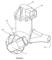
- FIG. 3 illustrates a bypass control valve 300 for a fuel cell according to a preferred embodiment.
- the bypass control valve 300 includes a first passage 320 defined by a wall 322 and disposed along a first axis A'.
- the first passage 320 has a first portion 330, a second portion 350, and a transitional portion 340 disposed between the first portion 330 and the second portion 350.
- the transitional portion 340 has a first port 342, a pivot point 344, and an annular locking member 346.
- the first port 342 is a generally cylindrically-shaped member, has a first diameter, and is disposed along a fourth axis D', which is parallel to the first axis A'.
- the first port 342 has a first sealing surface 348 disposed thereon.
- the first sealing surface 348 is a generally planar surface and can be disposed transverse to the first axis A'. Preferably, the first sealing surface 348 is oblique to the first axis A'.
- the annular locking member 346 is proximate the transitional portion 340. The annular locking member 346 also includes an annular seal 347.
- the bypass control valve 300 also includes a bypass passage 360 disposed along a second axis B', which is oblique to the first axis A'.
- the bypass passage 360 has a second port 362 which projects into the transitional portion 340.
- the second port 362 is a generally cylindrically-shaped member, has a second diameter, and is disposed along a fifth axis E', which is parallel to the second axis B'.
- the second diameter of the second port 362 can be different than the first diameter of the first port 342. It is believed that the diameters of the first port 342 and the second port 362 dictate the amount of pressure drop of downstream flow.
- the diameter of the second port 362 is generally the same or less than the first diameter of the first port 342.
- the second port 362 has a second sealing surface 364 and a receiver portion 366 coupled to the annular locking member 346.
- the second sealing surface 364 is a generally planar surface which can be disposed transverse to the second axis.
- the second sealing surface 364 is oblique to the second axis B'.
- bypass port 362 can be detached from the annular locking member 346 such that a different sized bypass port 362 and/or a different sized bypass passage 360 can be coupled to the first passage 320.
- the bypass port 362 and the passage 360 can be detached from the first passage 320 so as to facilitate maintenance of the first passage 320, including associated seals and a closure member 370.
- the closure member 370 includes elastomeric members disposed on a first planar surface 372, contiguous to the first port 342, and a second planar surface 374, contiguous to the second port 362.
- the closure member 370 can be a generally cylindrically shaped member.
- the closure member 370 is pivotally attached to the pivot point 344 and movable between a first position with the first planar surface 372 forming a seal with the first surface 348 of the first port 342 to prevent fluid flow from the second portion 350 to the first portion and vice versa.
- the closure member 370 can also be moved to a second position with the second planar surface 374 to form a seal with the second sealing surface 364 of the second port 362.
- the closure member 370 in the first position permits fluid communication between the first portion 330 and the bypass passage 360 and prevents fluid communication between the first portion 330 and the second portion 350.
- the closure member 370 in the second position permits fluid communication between the first portion 330 and the second portion 350 and prevents fluid communication between the first portion 330 and the bypass passage 360.
- the bypass control valve 300 also includes an actuator 380 ( Figures 4A and 4B), which is operable to rotate the closure member 370 between the first position and the second position.
- the actuator 380 has a shaft 382 that extends through the wall 322 to the pivot point 344 along a third axis C', which is orthogonal to the first axis A' and the second axis B'.
- the shaft 382 is coupled to the closure member 370 to rotate the closure member 370 about the pivot point 344.
- the actuator 380 can be powered by a pneumatic, hydraulic or electric primary drive source.
- an electric motor 500 ( Figure 5), is used to rotate the closure member 370 to a plurality of positions, including the first and second positions.
- the electric motor is enclosed in a housing 384, which is disposed on an exterior surface of the wall 322.
- the electric motor may be a stepper motor and is electrically connected to a position sensor (not shown) disposed proximate the shaft 382.
- the torque of the electric motor may be increased or decreased by a gearing arrangement (not shown) disposed between the electric motor and the shaft 382.
- the housing 384 can be made of metallic or polymeric material and is disposed along a sixth axis F', which is parallel to the third axis C'.
- the housing 384 can include an electrical connector 386 disposed on the exterior surface of the housing 384, and electrically connected to the electric stepper motor.
- the electric motor 500 can include a position sensor disposed in an interior surface 504 ( Figure 5) of the housing 384 proximate the rotor 510.
- the position sensor can comprise a stator sensor 516 fixed to the housing 384 and a rotor sensor 518 coupled to the rotor 510.
- a coil and bobbin assembly 512 of the electric motor can be disposed in the interior surface 504 of the housing 384 at an offset position relative to the axis F'.
- the electric motor 500 can also have a sensor disposed in the electric motor housing 502, the sensor including a rotor sensor 510 coupled to the driveshaft 508 and a stator sensor 516 disposed proximate the rotor sensor 510.
- the rotor 510 can be a generally cylindrical magnetic rotor. As illustrated in Figure 5, the generally cylindrical magnetic rotor can have a magnet portion 520 extending from the generally cylindrical magnetic rotor along the axis F' such that the magnet portion 520 projects beyond a planar surface defined by a base of the generally cylindrical magnetic rotor 510.
- the coil/bobbin assembly 512 can include a stator sensor 516, preferably a Hall effect sensor, coupled to the electric motor housing 502, such that when the magnetic portion 520 rotates about the stator sensor 516, a position of the magnetic portion 520 can be detected by the stator sensor 516.
- a stator sensor 516 preferably a Hall effect sensor
- the closure member 370 When an engine (not shown) is started, the closure member 370 is in the first position, air or a mixture of air and hydrogen is permitted to flow between the first portion 330 and the bypass passage 360. In the first position, the closure member 370 provides a fluid-tight seal between the first portion 330 and the second portion 350, thus preventing flow to the second portion 350.
- the electric motor (not shown) operates the actuator 380, which rotates the closure member 370 from the first position to the second position.
- the closure member 370 When the closure member 370 is in the second position, air or the air/hydrogen mixture is permitted to flow between the first portion 330 and the second portion 350.
- the closure member 370 provides a fluid-tight seal between the first portion 330 and the bypass passage 360, thus preventing air flow to the bypass passage 360.
- bypass control valve 10 in other applications requiring bypass flow control, such as, for example, heating and air conditioning air delivery systems or a precision fluid delivery system.
- the regulator valve 610 comprises a wall 612 defining a flow passage 614 disposed along a longitudinal axis A"-A".
- a closure member 616 is disposed in the flow passage 614 for rotation about an axis B"-B" oblique to the longitudinal axis A"-A".
- the closure member 616 is movable to a first position to prevent flow in the flow passage 614 and the closure member 616 is also movable to a second position to permit flow in the flow passage 614.
- a motive force device 700 is disposed along the axis B"-B" and coupled to the closure member 616 by an insulator member 802.
- the motive force device 700 is disposed such that it can rotate the closure member 616 between the first position and the second position about the axis B"-B".
- the valve also comprises a spacing chamber 800 having an inner wall 804 and an outer wall 806.
- the inner wall 804 forms a volume that houses the insulator member 802, the outer wall 806 of the spacing chamber 800 is coupled to the motive force device 700 and the flow passage 614.
- the flow passage 614 can include a boss portion with a seal 618 contiguous to the closure member 616 in the first position.
- the motive force device 700 can be an electric stepper motor.
- the electric motor can include a housing 702 having an interior surface 704 and an exterior surface 706, where the interior surface 704 encloses a driveshaft 708 coupled to a rotor 710 rotatable around the axis B"-B" and surrounded by a stator 712.
- the closure member 614 can be a butterfly valve, which can be coupled to a rod 620 disposed along the axis B"-B".
- the insulator member 802 can be an elastic metal member having a first end 808 and a second end 810, the first end 808 contiguous to the driveshaft 708 and the second end 810 contiguous to the rod 620 of the butterfly valve.
- the housing 702 can include an electrical connector 714 disposed on the exterior surface 706 of the housing 702, and electrically connected to the electric stepper motor.
- the motive force device 700 can include a sensor disposed in the interior surface 704 of the housing 702 proximate the rotor 710.
- the sensor can comprise a stator sensor 716 fixed to the housing 702 and a rotor sensor 718 coupled to the rotor 710.
- the stator 712 of the electric motor can be disposed in the interior surface 704 of the housing 702 at an offset position relative to the axis B"-B".
- the electric motor can also have a sensor disposed in the housing 702, the sensor including a rotor sensor 710 coupled to the driveshaft 708 and a stator sensor 716 disposed proximate the rotor sensor 710.
- the rotor 710 can be a generally cylindrical magnetic rotor.
- the generally cylindrical magnetic rotor can have a magnet portion 720 extending from the generally cylindrical magnetic rotor along the axis B"-B" such that the magnet portion 720 projects beyond a planar surface defined by a base of the generally cylindrical magnetic rotor 710.
- the stator 712 can include a stator sensor 716, such as a Hall effect sensor, coupled to the housing 702, such that the magnetic portion 720 rotates about the stator sensor 716.
- the heat transfer between a motive force device 700 and the exhaust backpressure valve 610 is believed to be decreased by coupling a chamber 800 having a defined volume to the motive force device 700 and the valve 610; and connecting the driveshaft 708 of the motive force device 700 to the actuating shaft 618 of the valve 610 with an insulator member 802.
Applications Claiming Priority (13)
| Application Number | Priority Date | Filing Date | Title |
|---|---|---|---|
| US21466700P | 2000-06-27 | 2000-06-27 | |
| US214667P | 2000-06-27 | ||
| US21463300P | 2000-06-28 | 2000-06-28 | |
| US21462700P | 2000-06-28 | 2000-06-28 | |
| US21462900P | 2000-06-28 | 2000-06-28 | |
| US214629P | 2000-06-28 | ||
| US214627P | 2000-06-28 | ||
| US214633P | 2000-06-28 | ||
| US24422700P | 2000-10-30 | 2000-10-30 | |
| US244227P | 2000-10-30 | ||
| 2001-06-11 | |||
| US09/888,618 US6830060B2 (en) | 2000-06-27 | 2001-06-26 | Air mass flow controller valve |
| US888618 | 2001-06-26 |
Publications (3)
| Publication Number | Publication Date |
|---|---|
| EP1170534A2 true EP1170534A2 (de) | 2002-01-09 |
| EP1170534A3 EP1170534A3 (de) | 2004-01-02 |
| EP1170534B1 EP1170534B1 (de) | 2006-02-01 |
Family
ID=28795393
Family Applications (1)
| Application Number | Title | Priority Date | Filing Date |
|---|---|---|---|
| EP01202472A Expired - Lifetime EP1170534B1 (de) | 2000-06-27 | 2001-06-27 | Brennstoffzellesteuerventile |
Country Status (2)
| Country | Link |
|---|---|
| EP (1) | EP1170534B1 (de) |
| DE (1) | DE60116951T2 (de) |
Cited By (6)
| Publication number | Priority date | Publication date | Assignee | Title |
|---|---|---|---|---|
| WO2016096875A1 (de) * | 2014-12-19 | 2016-06-23 | Continental Automotive Gmbh | Ventilvorrichtung in einem kraftfahrzeug |
| EP2592258B2 (de) † | 2011-11-08 | 2017-12-06 | Cooper-Standard Automotive (Deutschland) GmbH | Abgasrückführventil |
| CN111396603A (zh) * | 2019-01-02 | 2020-07-10 | 现代自动车株式会社 | 一种燃料电池系统的空气切断阀装置 |
| CN113942482A (zh) * | 2021-11-30 | 2022-01-18 | 中车大连机车车辆有限公司 | 一种轨道车辆总风缸自动排水的系统和方法 |
| EP4059774A1 (de) * | 2021-03-15 | 2022-09-21 | Alfmeier Präzision SE | Ventil, ventilanordnung und sitzkomfortsystem |
| US11920571B2 (en) | 2021-03-15 | 2024-03-05 | Alfmeier Präzision SE | Circuit arrangement and method to control at least one valve, valve, valve arrangement and seat comfort system |
Citations (11)
| Publication number | Priority date | Publication date | Assignee | Title |
|---|---|---|---|---|
| FR1487913A (fr) * | 1966-07-27 | 1967-07-07 | Dole Valve Co | Soupape à entrée unique et sorties multiples |
| US3415262A (en) * | 1965-10-22 | 1968-12-10 | Foster Wheeler Corp | Aspiration elimination for diverting valves |
| FR2043936A5 (de) * | 1969-05-02 | 1971-02-19 | Dubois Roger | |
| US3680831A (en) * | 1969-06-07 | 1972-08-01 | Katsuji Fujiwara | Electrically driven valve apparatus |
| US4718457A (en) * | 1986-06-20 | 1988-01-12 | Luger G William | Diverter valve |
| GB2208427A (en) * | 1987-08-03 | 1989-03-30 | Dufaylite Dev Ltd | Smoke diverter valve in air duct |
| FR2660396A1 (fr) * | 1990-03-27 | 1991-10-04 | Sueddeutsche Kalkstickstoff | Vanne a trois voies. |
| US5117856A (en) * | 1991-09-19 | 1992-06-02 | The Babcock & Wilcox Company | Flow range extending valve |
| GB2289743A (en) * | 1994-04-05 | 1995-11-29 | Rolls Royce Plc | Diverter valve |
| US5531205A (en) * | 1995-03-31 | 1996-07-02 | Siemens Electric Limited | Rotary diesel electric EGR valve |
| US5927682A (en) * | 1998-01-16 | 1999-07-27 | Mamac Systems, Inc. | Rotary drive coupler for actuated valve |
Family Cites Families (2)
| Publication number | Priority date | Publication date | Assignee | Title |
|---|---|---|---|---|
| JP2655362B2 (ja) * | 1990-07-27 | 1997-09-17 | 自動車部品工業株式会社 | 流路切替バルブ装置 |
| JPH11201320A (ja) * | 1998-01-08 | 1999-07-30 | Kitz Corp | バルブの結露防止装置 |
-
2001
- 2001-06-27 DE DE60116951T patent/DE60116951T2/de not_active Expired - Lifetime
- 2001-06-27 EP EP01202472A patent/EP1170534B1/de not_active Expired - Lifetime
Patent Citations (11)
| Publication number | Priority date | Publication date | Assignee | Title |
|---|---|---|---|---|
| US3415262A (en) * | 1965-10-22 | 1968-12-10 | Foster Wheeler Corp | Aspiration elimination for diverting valves |
| FR1487913A (fr) * | 1966-07-27 | 1967-07-07 | Dole Valve Co | Soupape à entrée unique et sorties multiples |
| FR2043936A5 (de) * | 1969-05-02 | 1971-02-19 | Dubois Roger | |
| US3680831A (en) * | 1969-06-07 | 1972-08-01 | Katsuji Fujiwara | Electrically driven valve apparatus |
| US4718457A (en) * | 1986-06-20 | 1988-01-12 | Luger G William | Diverter valve |
| GB2208427A (en) * | 1987-08-03 | 1989-03-30 | Dufaylite Dev Ltd | Smoke diverter valve in air duct |
| FR2660396A1 (fr) * | 1990-03-27 | 1991-10-04 | Sueddeutsche Kalkstickstoff | Vanne a trois voies. |
| US5117856A (en) * | 1991-09-19 | 1992-06-02 | The Babcock & Wilcox Company | Flow range extending valve |
| GB2289743A (en) * | 1994-04-05 | 1995-11-29 | Rolls Royce Plc | Diverter valve |
| US5531205A (en) * | 1995-03-31 | 1996-07-02 | Siemens Electric Limited | Rotary diesel electric EGR valve |
| US5927682A (en) * | 1998-01-16 | 1999-07-27 | Mamac Systems, Inc. | Rotary drive coupler for actuated valve |
Non-Patent Citations (2)
| Title |
|---|
| PATENT ABSTRACTS OF JAPAN vol. 016, no. 314 (M-1278), 9 July 1992 (1992-07-09) & JP 04 088270 A (JIDOUSHIYA BUHIN KOUGIYOU KK), 23 March 1992 (1992-03-23) * |
| PATENT ABSTRACTS OF JAPAN vol. 1999, no. 12, 29 October 1999 (1999-10-29) & JP 11 201320 A (KITZ CORP), 30 July 1999 (1999-07-30) * |
Cited By (9)
| Publication number | Priority date | Publication date | Assignee | Title |
|---|---|---|---|---|
| EP2592258B2 (de) † | 2011-11-08 | 2017-12-06 | Cooper-Standard Automotive (Deutschland) GmbH | Abgasrückführventil |
| WO2016096875A1 (de) * | 2014-12-19 | 2016-06-23 | Continental Automotive Gmbh | Ventilvorrichtung in einem kraftfahrzeug |
| CN107110376A (zh) * | 2014-12-19 | 2017-08-29 | 大陆汽车有限责任公司 | 机动车中的阀装置 |
| CN111396603A (zh) * | 2019-01-02 | 2020-07-10 | 现代自动车株式会社 | 一种燃料电池系统的空气切断阀装置 |
| EP4059774A1 (de) * | 2021-03-15 | 2022-09-21 | Alfmeier Präzision SE | Ventil, ventilanordnung und sitzkomfortsystem |
| US11794610B2 (en) | 2021-03-15 | 2023-10-24 | Alfmeier Präzision SE | Valve, valve assembly, and seat comfort system |
| US11920571B2 (en) | 2021-03-15 | 2024-03-05 | Alfmeier Präzision SE | Circuit arrangement and method to control at least one valve, valve, valve arrangement and seat comfort system |
| CN113942482A (zh) * | 2021-11-30 | 2022-01-18 | 中车大连机车车辆有限公司 | 一种轨道车辆总风缸自动排水的系统和方法 |
| CN113942482B (zh) * | 2021-11-30 | 2024-02-02 | 中车大连机车车辆有限公司 | 一种轨道车辆总风缸自动排水的系统和方法 |
Also Published As
| Publication number | Publication date |
|---|---|
| EP1170534B1 (de) | 2006-02-01 |
| DE60116951D1 (de) | 2006-04-13 |
| EP1170534A3 (de) | 2004-01-02 |
| DE60116951T2 (de) | 2006-07-27 |
Similar Documents
| Publication | Publication Date | Title |
|---|---|---|
| EP0957298B1 (de) | Durchflussmengen-Regelventil, insbesondere für begaste Flüssigkeiten | |
| US6648018B2 (en) | Bypass control valve | |
| US6455185B2 (en) | Reformate control valve assembly for a fuel cell | |
| US7533690B2 (en) | Multi-functional regulator | |
| US7401762B2 (en) | Solenoid-operated valve for use with fuel cells | |
| US20140346380A1 (en) | Electrically Operated Valve Assembly | |
| WO1989001105A1 (en) | Electrically actuated egr valve | |
| US6878472B2 (en) | Air mass flow controller | |
| US6321765B2 (en) | Method of operation of mass flow controller | |
| EP1170534A2 (de) | Brennstoffzellesteuerventile | |
| EP3039322B1 (de) | Kombinierte wärmeverwaltungseinheit | |
| US7302969B2 (en) | Valve device for use with fuel cells | |
| US6705341B2 (en) | Mass flow controller | |
| US6830060B2 (en) | Air mass flow controller valve | |
| JP2013522528A (ja) | 燃料を供給するための圧力制御部、およびこの圧力制御部を備える制御ユニットを有する燃料供給システム | |
| US6817380B2 (en) | Diffuser in an air mass flow controller | |
| JP2002530592A (ja) | 燃料流体噴射回路のための直接制御燃料バルブ | |
| US20230235706A1 (en) | Integrated throttle - fuel mixer | |
| CN111936948A (zh) | 流量控制装置 | |
| JP2548151B2 (ja) | ガス制御装置 | |
| JPS62106103A (ja) | 空気圧インタ−フエ−ス装置 | |
| CN117588596A (zh) | 流体控制阀和流体控制装置 | |
| JP4303181B2 (ja) | 内燃機関のスロットル装置 | |
| JP2605864B2 (ja) | 流量制御弁 | |
| JPS61278674A (ja) | 電動弁 |
Legal Events
| Date | Code | Title | Description |
|---|---|---|---|
| PUAI | Public reference made under article 153(3) epc to a published international application that has entered the european phase |
Free format text: ORIGINAL CODE: 0009012 |
|
| AK | Designated contracting states |
Kind code of ref document: A2 Designated state(s): AT BE CH CY DE DK ES FI FR GB GR IE IT LI LU MC NL PT SE TR |
|
| AX | Request for extension of the european patent |
Free format text: AL;LT;LV;MK;RO;SI |
|
| RIC1 | Information provided on ipc code assigned before grant |
Ipc: 7F 16K 11/10 B Ipc: 7H 01M 8/04 B Ipc: 7F 16K 31/06 B Ipc: 7F 16K 31/04 B Ipc: 7F 16K 11/052 B Ipc: 7F 16K 11/20 A |
|
| PUAL | Search report despatched |
Free format text: ORIGINAL CODE: 0009013 |
|
| AK | Designated contracting states |
Kind code of ref document: A3 Designated state(s): AT BE CH CY DE DK ES FI FR GB GR IE IT LI LU MC NL PT SE TR |
|
| AX | Request for extension of the european patent |
Extension state: AL LT LV MK RO SI |
|
| RAP1 | Party data changed (applicant data changed or rights of an application transferred) |
Owner name: SIEMENS AUTOMOTIVE INC. |
|
| 17P | Request for examination filed |
Effective date: 20040202 |
|
| RAP1 | Party data changed (applicant data changed or rights of an application transferred) |
Owner name: SIEMENS VDO AUTOMOTIVE INC. |
|
| 17Q | First examination report despatched |
Effective date: 20040430 |
|
| AKX | Designation fees paid |
Designated state(s): DE FR GB IT SE |
|
| GRAP | Despatch of communication of intention to grant a patent |
Free format text: ORIGINAL CODE: EPIDOSNIGR1 |
|
| GRAS | Grant fee paid |
Free format text: ORIGINAL CODE: EPIDOSNIGR3 |
|
| GRAA | (expected) grant |
Free format text: ORIGINAL CODE: 0009210 |
|
| AK | Designated contracting states |
Kind code of ref document: B1 Designated state(s): DE FR GB IT SE |
|
| REG | Reference to a national code |
Ref country code: GB Ref legal event code: FG4D |
|
| REF | Corresponds to: |
Ref document number: 60116951 Country of ref document: DE Date of ref document: 20060413 Kind code of ref document: P |
|
| REG | Reference to a national code |
Ref country code: SE Ref legal event code: TRGR |
|
| ET | Fr: translation filed | ||
| PLBE | No opposition filed within time limit |
Free format text: ORIGINAL CODE: 0009261 |
|
| STAA | Information on the status of an ep patent application or granted ep patent |
Free format text: STATUS: NO OPPOSITION FILED WITHIN TIME LIMIT |
|
| 26N | No opposition filed |
Effective date: 20061103 |
|
| PGFP | Annual fee paid to national office [announced via postgrant information from national office to epo] |
Ref country code: GB Payment date: 20140618 Year of fee payment: 14 |
|
| PGFP | Annual fee paid to national office [announced via postgrant information from national office to epo] |
Ref country code: IT Payment date: 20140623 Year of fee payment: 14 Ref country code: DE Payment date: 20140630 Year of fee payment: 14 Ref country code: SE Payment date: 20140618 Year of fee payment: 14 |
|
| PGFP | Annual fee paid to national office [announced via postgrant information from national office to epo] |
Ref country code: FR Payment date: 20140619 Year of fee payment: 14 |
|
| REG | Reference to a national code |
Ref country code: DE Ref legal event code: R119 Ref document number: 60116951 Country of ref document: DE |
|
| PG25 | Lapsed in a contracting state [announced via postgrant information from national office to epo] |
Ref country code: IT Free format text: LAPSE BECAUSE OF NON-PAYMENT OF DUE FEES Effective date: 20150627 |
|
| REG | Reference to a national code |
Ref country code: SE Ref legal event code: EUG |
|
| GBPC | Gb: european patent ceased through non-payment of renewal fee |
Effective date: 20150627 |
|
| PG25 | Lapsed in a contracting state [announced via postgrant information from national office to epo] |
Ref country code: SE Free format text: LAPSE BECAUSE OF NON-PAYMENT OF DUE FEES Effective date: 20150628 |
|
| REG | Reference to a national code |
Ref country code: FR Ref legal event code: ST Effective date: 20160229 |
|
| PG25 | Lapsed in a contracting state [announced via postgrant information from national office to epo] |
Ref country code: GB Free format text: LAPSE BECAUSE OF NON-PAYMENT OF DUE FEES Effective date: 20150627 Ref country code: DE Free format text: LAPSE BECAUSE OF NON-PAYMENT OF DUE FEES Effective date: 20160101 |
|
| PG25 | Lapsed in a contracting state [announced via postgrant information from national office to epo] |
Ref country code: FR Free format text: LAPSE BECAUSE OF NON-PAYMENT OF DUE FEES Effective date: 20150630 |